PA1240 - Mixer Monacor - Free user manual and instructions
Find the device manual for free PA1240 Monacor in PDF.

| Product type | 5-zone Public Address amplifier-mixer |
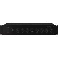
| Brand and model | Monacor PA1240 |
| Dimensions (W × H × D) | 482 × 133 × 352 mm (3U rack 19") |
| Weight | 14 kg |
| Power supply | Mains 230 V / 50 Hz, 630 VA; backup 24 V DC, 27 A |
| Rated output power | 5 × 100 W (100 V zones) or 1 × 240 W (4 Ω output), max total 240 W RMS |
| Microphone/line inputs CH1–CH3 | 3 × balanced combo XLR/6.35 mm jack, sensitivity 2.5–300 mV, 5 kΩ, switchable 17 V phantom power |
| Line inputs CH4 and CH5 | 2 × unbalanced RCA, 300 mV, 15 kΩ |
| Paging telephone input PAGING IN | Balanced screw terminal, 250 mV, 5 kΩ |
| Extension module input | Slot for tuner, CD player or digital message module (accessories) |
| Speaker outputs | 5 × 100 V (zones Z1–Z5) + 1 × 4 Ω (min. impedance 4 Ω) |
| Line outputs | REC (RCA, 775 mV/3 kΩ) and PRE OUT (6.35 mm jack, 775 mV/100 Ω) |
| Frequency range | 55–16000 Hz (-3 dB) |
| Equalizer (per channel) | Bass ±10 dB at 100 Hz, Treble ±10 dB at 10 kHz |
| Signal-to-noise ratio | Line >80 dB (A-weighted), Mic >70 dB (A-weighted) |
| Distortion rate | <1% |
| Protections | Thermal protection (TEMP LED 100 °C), overload protection (PROT LED) |
| Main functions | 5-zone mixing, adjustable priority per channel, 2/4-tone chime, siren (warbling/continuous), telephone, priority announcement via relay, automatic alarm |
| Maintenance and cleaning | Soft dry cloth, no chemicals or water |
| Operating temperature | 0–40 °C |
| Spare parts and repairability | Repair by qualified technician only; parts from manufacturer |
| Compatible accessories | Table microphones PA-4000PTT, PA-4300PTT; remote microphone PA-1120RC; insert modules PA-1120DMT / PA-1140RCD / PA-1200RDSU |
Frequently Asked Questions - PA1240 Monacor
User questions about PA1240 Monacor
0 question about this device. Answer the ones you know or ask your own.
Ask a new question about this device
Download the instructions for your Mixer in PDF format for free! Find your manual PA1240 - Monacor and take your electronic device back in hand. On this page are published all the documents necessary for the use of your device. PA1240 by Monacor.
USER MANUAL PA1240 Monacor
New option for microphone priority starting from serial number ...-03
For all devices whose serial number ends with "-03", the priority of the input channels CH1–CH3 and of the siren can be switched off. To do this, disconnect the device from the power supply and remove the housing cover. Set the switch SW1 in the rear part of the device to the position OFF (drawing). The signals of the channels CH1 – CH3 and of the siren will then no longer fade out the signals of the channels CH4 – CH5, for example, but they will mix with these signals.
It will, however, still be possible to individually assign a higher priority (3rd priority level) to the channels CH1–CH3 by means of the corresponding switch MIC PRIORITY.
natural_image
Front view of a desktop computer interface with a microphone and control panel (no visible text or symbols)PA-1120RC
natural_image
White desktop computer with a black adjustable arm and a small button on the base (no visible text or symbols)PA-4000PTT
natural_image
Exterior view of a desktop computer with a microphone and indicator device (no visible text or symbols)PA-4300PTT
text_image
MONACOR TA-30001 TALK 50 51 ③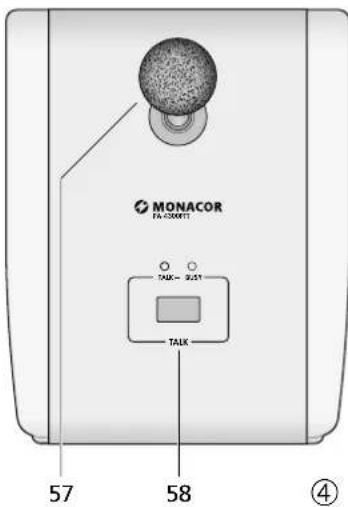
text_image
MONACOR FA-3001T TAUX 9.21 TAUX 57 58 ④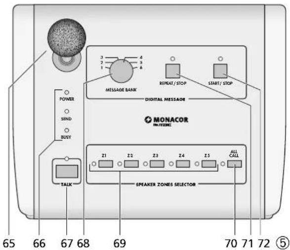
text_image
65 66 67 68 69 70 71 72 ⑤ POWER SEND BUSY TALK MESSAGE BANK REPEAT/STOP START/STOP DIGITAL MESSAGE MONACOR PANTEDEC Z1 Z2 Z3 Z4 Z5 ALL CALL SPEAKER ZONES SELECTORPA Mixing Amplifier for 5 Zones
These instructions are intended for installers of PA systems (chapters 1 – 10) and for users without any specific technical knowledge (chapters 1 – 3, 8). Please read the instructions carefully prior to operation and keep them for later reference.
All operating elements and connections described can be found on the fold-out page 3.
Contents
1 Overview 10
1.1 Front panel of amplifier ..... 10
1.2 Rear panel of amplifier. 10
1.3 Desk microphone PA-4000PTT (accessory) . 11
1.4 Desk microphone PA-4300PTT (accessory) . 11
1.5 Zone paging microphone PA-1120RC (accessory) ..... 11
2 Safety Notes 11
3 Applications and Accessories ..... 12
4 Setting up the Amplifier. 12
4.1 Rack installation 12
5 Adjusting the Chime Sound and the Priority of the Insertion Module 12
6 Connections 12
6.1 Speakers 12
6.2 Microphones 12
6.3 Desk microphone PA-4000PTT or PA-4300PTT 12
6.4 Zone paging microphone PA-1120RC . . . . 12
6.4.1 Installation of the connection module . . . 12
6.4.2 Microphone connection and basic setting . 13
6.5 Units with line level / audio recorder ..... 13
6.6 Inserting the equalizer or another unit . . . 13
6.7 Additional amplifier ..... 13
6.8 Telephone bell or night bell ..... 13
6.9 Emergency priority relays ..... 13
6.10 Switch for (automatic) announcements in all zones. 13
6.11 Telephone switchboard 13
6.12 Switching on / off by remote control. . . . . 13
6.13 Power supply and emergency power supply . 13
7 Defining the Priority of Input Signals . . 14
8 Operation 14
8.1 Adjusting the volume ..... 14
8.2 Activating the PA zones ..... 14
8.3 Chime 14
8.4 Alarm siren 14
8.5 Desk microphone PA-4000PTT or PA-4300PTT 14
8.6 Zone paging microphone PA-1120RC . . . . 14
9 Protective Circuit. 15
10 Specifications 15
Layout and connection plan . . . . . . . . . . . . . . . . 48
Block diagram....49
1 Overview
1.1 Front panel of amplifier
1 Cover of the insertion compartment; a MONACOR insertion can be installed here, e. g. tuner, CD player, digital message insertion
2 TREBLE control for a unit inserted into the compartment (1)
3 BASS control for a unit inserted into the compartment (1)
4 Buttons with LED indicator for activating the individual PA zones Z 1 to Z 5
5 Zone attenuators for separate volume adjustment of the individual zones
6 Button ALL CALL with LED indicator for activating all zones at the same time and for increasing the volume to the maximum [independent of the buttons (4) and the zone attenuators (5)]; the maximum volume is only limited by the MASTER control (21)
7 LED indicators for the power amplifier [independent of the zone attenuators (5)]; in case of overload, the red LED CLIP will light up
8 Level controls for the inputs CH 1 to CH 3 (39) Control CH 1 will also adjust the level for a microphone connected to the jack (43) or (44); control CH 2 will adjust the level for zone paging microphones of type PA-1120RC (connected via a separate module): the priority of these inputs is adjusted with the DIP switches (45)
9 Bass and treble controls for the inputs CH 1 to CH 3 (39)
10 Level controls for the line inputs CH 4 and CH 5 (38)
11 Bass and treble controls for the inputs CH 4 and CH 5
12 Chime button; the chime will take 2^nd priority (for switching over between 2-tone chime and 4-tone chime see chapter 5)
13 Volume control for the chime
14 Button TEL; if the button is pressed, it will e. g. be possible to hear a telephone bell or night bell via all speakers [connection via the terminals NIGHT RINGER (29)]; the bell will take the lowest priority
15 Volume control for a telephone signal fed in via the terminals PAGING IN (32); this signal will take 3^rd priority
16 Volume control for the telephone bell or night bell (also see items 14 and 29)
17 Button for a wailing siren tone; the siren will take 4^th priority
18 Volume control for the siren
19 Button for a steady siren tone
20 Overheat indicator TEMP; will light up when the temperature of the heat sink has reached 100 °C . In this case, all speaker outputs will be muted. In addition, the red LED PROT (22) will light up.
21 MASTER control for the total volume
22 LED PROT; will light up when the protective circuit is activated:
-
for approx. 1 second after switching on (switch-on delay)
-
for approx. 1 second after switching off
-
if the amplifier is overloaded
-
if the amplifier is overheated
23 POWER LEDs:
DC will light up when the amplifier uses a 24V emergency supply voltage in case of mains failure
AC will light up when the amplifier uses the mains voltage
24 POWER switch
25 STAND BY LED;
will light up when the amplifier is switched off
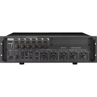
1.2 Rear panel of amplifier
26 Speaker terminals for 100 V speakers
Attention! Each of the five zone outputs allows a maximum load of 100 W RMS by the speakers; however, the total load of all zones must never exceed the following value:
PA-1120 120W RMS
PA-1240 240W RMS
27 Jack for the mains cable supplied for connection to 230V/50Hz
28 4 Ω speaker output for a speaker group with a total minimum impedance of 4 Ω
Attention! Only use this output if the 100 V outputs (26) are not used, otherwise you will risk overload of the amplifier.
29 Input for the bell voltage (e. g. 8 V/50 Hz) of a telephone bell or night bell; the bell voltage will trigger an audio signal which can be heard via the speakers (also see items 14 and 16)
30 Screw terminals for an emergency power supply ( ≈ 24V)
31 Screw terminals for an external switch for activation/deactivation by remote control [in this case, the switch POWER (24) must not be pressed]
32 Input (bal., 250 mV) for a telephone signal to be heard via the PA system (also see item 15)
33 Connection for a separate switch; if a digital message insertion PA-1120DMT is installed, this connection allows to call up a stored alarm announcement. At the same time, all PA zones will be activated and set to maximum volume [like the button ALL CALL (6)]
34 Cover plate; will be replaced by a connection plate if the insertion PA-1120DMT, PA-1140RCD or PA-1200RDSU is installed
35 Input AMP IN; in connection with the output PRE OUT (36) for inserting e. g. an equalizer. If this jack is connected, only the signal fed in here will be reproduced. The power amplifier will be disconnected from the preamplifier.
36 Output PRE OUT; for connection of an additional amplifier (chapter 6.7) or in connection with the input AMP IN (35) for inserting e.g. an equalizer; the output volume is independent of the MASTER control (21)
37 Output REC for connecting a recorder; the output volume is independent of the MASTER control (21)
38 Inputs CH 4 and CH 5 for units with line level (e.g. CD player, cassette recorder, etc.); the two stereo channels L and R will be mixed internally to a mono signal
39 Balanced inputs CH 1 to CH 3 via XLR / 6.3 mm jacks (combined jacks); the input sensitivity can be adjusted between microphone level and line level (2.5 – 250 mV) with the controls GAIN (41)
40 Switch PHANTOM POWER for switching on the 17 V power supply for phantom-powered microphones; for the inputs CH 1 to CH 3 Attention! If the 17 V power supply is connected, never connect a microphone with unbalanced output to the corresponding input jack (39); otherwise, the microphone may be damaged.
41 Control for adjusting the input sensitivity; for the inputs CH 1 to CH 3 (see item 39)
42 Screw terminals for connecting emergency priority relays, see chapter 5.9
43 Jack PA-4000PTT for connecting a PA desk microphone of type PA-4000PTT
44 Jack PA-4300PTT for connecting a PA desk microphone of type PA-4300PTT
45 DIP switches MIC PRIORITY; in position ON, the corresponding input (CH 1, CH 2 or CH 3) will be set from 4^th to 3^rd priority
46 Cover plate; if the zone paging microphone PA-1120RC is inserted, the connection module will be installed here
1.3 Desk microphone PA-4000PTT (accessory)
Important! For operating the microphone, always observe chapter 6.3.
47 DIP switch CHIME;
in position ON, the chime will sound when
the TALK button (51) is pressed
48 DIP switch PRIORITY;
OFF: the microphone will take 4^th priority
ON: the microphone will take 2^nd priority when the TALK button is pressed, all PA zones will be activated and set to maximum volume [like button ALL CALL (6)], and at the terminals PRIORITY RELAY OUTPUT (42), 24 V / 0.2 A max. are available for switching emergency priority relays (see chapter 6.9)
49 RJ-45 jack for connection to jack PA-4000PTT (43) of the amplifier
50 Microphone cartridge with windshield
51 TALK button; when pressed, the green LED above the button will light up
1.4 Desk microphone PA-4300PTT (accessory)
Important! For operating the microphone, always observe chapter 6.3.
52 DIP switch CHIME;
in position ON, the chime will sound when
the TALK button (58) is pressed
53 DIP switch PRIORITY;
OFF: the microphone will take 4^th priority
ON: the microphone will take 2^nd priority when the TALK button is pressed, all PA zones will be activated and set to maximum volume [like button ALL CALL (6)], and at the terminals PRIORITY RELAY OUTPUT (42), 24 V / 0.2 A max. are available for switching emergency priority relays (see chapter 6.9)
54 Switch MASTER / SLAVE for defining the priority when further microphones PA-4300PTT are connected
SLAVE other microphones set to MASTER will take priority
MASTER the microphone will take priority over microphones set to SLAVE
55 RJ-45 jack OUTPUT for connection to jack PA-4300PTT (44) of the amplifier
56 RJ-45 jack LINK for connection of an additional microphone PA-4300PTT (a maximum of 3 interconnected microphones can be connected to the amplifier)
57 Microphone cartridge with windshield
58 TALK button; when pressed, the green LED above the button will light up
The red LED BUSY lights up when another PA-4300PTT with the switch MASTER/SLAVE set to the position MASTER is used for making announcements.
1.5 Zone paging microphone PA-1120RC (accessory)
For operation of the PA-1120RC, the connection module supplied with the microphone must be installed (see chapter 5.4.).
59 Switch DIGITAL MESSAGE; in position ON, the stored announcements can be called up*
60 Switch TALK for defining the priority when further microphones PA-1120RC are connected
SLAVE other microphones set to PRIORITY will take priority
PRIORITY the microphone will take priority over microphones set to SLAVE
61 Jack LINK for connecting further zone paging microphones of type PA-1120RC
62 Jack OUTPUT for connection to the jack INPUT of the connection module supplied with the microphone
63 Input jacks AUX IN for an additional audio signal with line level
64 Output level control for the microphone signal and the signal from the jacks AUX IN (63)
65 Microphone cartridge with windshield
66 LED indicators POWER power LED (amplifier switched on) SEND will light up when you make an announcement or when a stored announcement* is called up BUSY will light up when you make an announcement or when announcements are made via other microphones PA-1120RC connected
67 TALK button
68 Rotary switch for selecting a stored announcement*
69 Buttons Z1-Z5 with LED indicators for activating the zones where the announcement is to be heard
70 Button ALL CALL with LED indicator for activating all zones at the same time [like button (6)]
71 Button REPEAT/ STOP for multiple reproduction of a stored announcement*; to terminate the announcement, press the button again
72 Button START/ STOP to reproduce a stored announcement*, to terminate the announcement, press the button again
2 Safety Notes
This unit corresponds to all relevant directives of the EU and is therefore marked with €€
WARNING
The unit is supplied with hazardous mains voltage. Leave servicing to skilled personnel only. Never insert anything into the air vents. Inexpert handling may cause an electric shock hazard.

During operation, dangerous voltage of up to 100 V is available at the speaker terminals (26). Always switch off the amplifier before making or changing any connections.
- Even when it is switched off, the amplifier is not completely disconnected from the mains voltage; it still has a low power consumption.
- The unit is suitable for indoor use only. Protect it against dripping water and splash water, high air humidity and heat (admissible ambient temperature range 0–40°C).
- Do not place any vessel filled with liquid on the unit, e.g. a drinking glass.
- The heat generated within the unit must be dissipated by air circulation. Never cover the air vents.
-
Do not operate the unit or immediately disconnect the plug from the mains socket
-
if there is visible damage to the unit or to the mains cable,
- if a defect might have occurred after the unit was dropped or suffered a similar accident,
-
if malfunctions occur. In any case the unit must be repaired by skilled personnel.
-
Never pull the mains cable when disconnecting the mains plug from the socket, always seize the plug.
- For cleaning only use a dry, soft cloth; never use chemicals or water.
- No guarantee claims for the unit or liability for any resulting personal damage or material damage will be accepted if the unit is used for other purposes than originally intended, if it is not correctly connected or operated, or if it is not repaired in an expert way.

If the unit is to be put out of operation definitively, take it to a local recycling plant for a disposal which is not harmful to the environment.
3 Applications and Accessories
This amplifier has especially been designed for use in 100 V PA systems. 100 V outputs for up to five PA zones are available whose volume can be individually adjusted. Microphones or units with line level can be connected via three inputs whose priority can be individually adjusted. Two further line inputs of lowest priority complement the connection possibilities.
| Accessories | |
| Insertion modules for the extension compartment (1) | |
| PA-1120DMT | digital message storage with timer |
| PA-1140RCD | radio/CD player |
| PA-1200RDSU | AM / FM radio with audio player |
| PA desk microphones especially designed for this amplifier | |
| PA-4000PTT (fig. 3) | A desk microphone may be connected to the jack PA-4000PTT (43). |
| PA-4300PTT (fig. 4) | A desk microphone may be connected to the jack PA-4300PTT (44). A maximum of three microphones PA-4300PTT may be operated with the amplifier. |
| PA-1120RC (fig. 5) | Three zone paging microphones may be connected; the microphone is supplied with a connection module which is inserted into the amplifier. |
4 Setting up the Amplifier
The amplifier has been designed for installation into a rack (482 mm /19"), however, it can also be used as a table top unit. In any case, air must be allowed to pass through all air vents to ensure sufficient cooling of the power amplifier.
4.1 Rack installation
For rack installation, the amplifier requires 3 RS (3 rack spaces = 133 mm). To prevent the rack from becoming top-heavy, insert the amplifier into the lower section of the rack. The front plate is not sufficient for fixing the amplifier safely; additionally use lateral rails or a bottom plate to secure the amplifier.
The hot air given at the sides of the amplifier must be dissipated from the rack; otherwise heat will accumulate in the rack which may not only damage the amplifier but also other units in the rack. In case of insufficient heat dissipation, insert a ventilation unit into the rack above the amplifier (p. ex. DPVEN-04).
5 Adjusting the Chime Sound and the Priority of the Insertion Module
Prior to installing an insertion into the compartment (1), adjust the two jumpers MS 1 (chime) and MS 2 (priority of the insertion), see layout diagram page 48. These are no longer accessible when an insertion is installed.
1) Disconnect the amplifier from the mains and from the emergency power supply.
2) Screw off the cover (1) for the insertion.
3) Adjust the chime sound with the jumper MS 1:
position "4 Tone": 4-tone chime
position "2 Tone": 2-tone chime
4) Adjust the priority for the insertion module with the jumper MS 2:
position "SLAVE" (factory setting):
The signal of the insertion takes the lowest priority.
position "PRI":
The signal of the insertion takes 2^nd priority. This adjustment must e.g. be selected for calling up stored announcements from the digital message storage PA-1120DMT via the zone paging microphone PA-1120RC.
A survey of all possible priorities is given in chapter 7 "Defining the Priority of the Input Signals".
5) If no insertion is installed, tightly fasten the cover (1) using screws.
6 Connections
All connections should only be made by skilled personnel. Always switch off the amplifier before making any connection!
6.1 Speakers
Either connect 100 V speakers for the five PA zones to the screw terminals SPEAKER ZONES ATT. OUTPUTS (26)
Attention! Each of the five zone outputs may be loaded by the speakers with 100 W RMS as a maximum. However, the total load of all zones must never exceed the following value: PA-1120 120WRMS PA-1240 240WRMS
or connect a speaker group with a total impedance of 4 Ω as a minimum to the screw terminals LOW IMP 4 Ω (28). The zone volume switches (5) do not affect this output. Never use the 100 V outputs (26) and the 4 Ω output (28) at the same time; otherwise, the amplifier will be overloaded!
When connecting the speakers, always observe the correct polarity, i. e. connect the positive contact of the speakers to the upper terminal. The positive contact of the speaker cables is always especially marked.
6.2 Microphones
Connect three microphones with an XLR or 6.3 mm plug to the combined XLR / 6.3 mm jacks (39) of the inputs CH 1 to 3.
1) When connecting a microphone, turn the corresponding GAIN control (41) fully to the right to position “-50”.
2) When using a phantom-powered microphone, switch on the 17 V supply with the corresponding button PHANTOM POWER (40).
Caution! Only actuate the switch with the amplifier switched off (switching noise). With the button pressed, no microphone with unbalanced output must be connected to the corresponding input; the microphone may be damaged.
3) If a microphone is to take priority over another microphone, set the corresponding DIP switch MIC PRIORITY (45) to position ON (also see chapter 7).
Notes:
- When the desk microphone PA-4000PTT (fig. 3) or PA-4300PTT (fig. 4) is used, the input CH 1 must not be used as this input is connected in parallel with the input (43) for the PA-4000PTT and with the input (44) for the PA-4300PTT.
- If a zone paging microphone PA-1120RC is connected, the input CH 2 must not be used as this input is connected in parallel with the input for the PA-1120RC (via the corresponding connection module).
6.3 Desk microphone PA-4000PTT or PA-4300PTT
The desk microphones PA-4000PTT (fig. 3) and PA-4300PTT (fig. 4) [separately available as accessory components] have been especially designed for this amplifier.
1) Use the RJ-45 jack PTT REMOTE (49) to connect the microphone PA-4000PTT to the jack PA-4000PTT (43) of the amplifier or use the jack OUTPUT (55) to connect the microphone PA-4300PTT to the jack PA-4300PTT (44) of the amplifier.
2) It is possible to connect two additional microphones of the model PA-4300PTT: Connect the jack LINK (56) of the first microphone to the jack OUTPUT (55) of the second microphone. Proceed in the same way to connect the third microphone to the second one.
3) Press the switch PHANTOM POWER (40) of input CH 1 and turn the corresponding GAIN control (41) fully to the right to the position "-50".
Notes:
- Channel CH 1 is now connected in parallel to the jacks for the desk microphones and may therefore not be used for any other input signals anymore.
- The total length of the microphone cable may not exceed 1000 m.
6.4 Zone paging microphone PA-1120RC
The zone paging microphone PA-1120RC (fig. 5) available as a separate accessory has especially been designed for this amplifier. Up to 3 zone paging microphones may be connected. For operation, the connection module supplied with the microphone must be installed into the amplifier first. Installation must be made by skilled personnel only!
Note: When using the zone paging microphone, the input CH 2 must not be used for other input signals as this input is connected in parallel with the input for the zone paging microphone.
6.4.1 Installation of the connection module
1) Disconnect the mains plug from the mains socket. If an emergency power supply is connected, disconnect it from the terminals 24V= (30) so that the amplifier is out of operation in any case. Unscrew the housing cover of the amplifier and the cover plate (46) on the rear side of the amplifier.
2) Connect the 3-pole line AS 903 C of the connection module to the jack CN 903 C of the amplifier – see layout diagram page 48.
3) Insert the module into the cutouts which are uncovered when removing the cover (46) and then fasten it tightly using screws.
4) Connect the loose, two-pole line A in the amplifier with a black core and a red core from the connection AS801 to the jack CN801 A of the module.
5) Connect the screened line AS 802 B of the module to the jack AN 802 B of the amplifier.
6) Connect the 6-pole line AS 204 D of the module to the jack CN901 D of the amplifier.
7) If no digital message insertion PA-1120DMT is installed, fasten the loose 10-pole line AS 4-1 of the module with cable ties in the amplifier.
Only make the steps 8) to 10) with the digital message insertion PA-1120DMT installed:
8) Connect the 10-pole line AS 4-1 of the module to the jack CN4-1 of the insertion.
9) Use the jumper MS 802 of the connection module to define if the announcement in
the storage M 6 of the PA-1120DMT can be called up via the zone paging microphone (position ON) or not (position OFF, factory setting). The storage M 6 can e. g. be used for an alarm announcement which is only to be activated via the terminals MESSAGE FIRST PRIORITY (33).
10) In the amplifier, set the jumper MS 2 to position PRI. Thus, the volume of an announcement from the insertion will not be attenuated by a signal of the zone paging microphone.
6.4.2 Microphone connection and basic setting
1) Connect the jack OUTPUT (62) of the microphone to the jack INPUT of the connection module. A short connection cable is supplied with the microphone. The cable length between amplifier and microphone must be 1000 m as a maximum.
A 2^nd microphone may be connected via its jack OUTPUT to the jack LINK of the module or to the jack LINK (61) of the 1^st microphone. For the connection of a 3^rd microphone, connect its jack OUTPUT to the jack LINK of the 2^nd microphone. As a maximum, three microphones may be connected. The cable length between two microphones must not exceed 100 m.
2) When using several microphones of type PA-1120RC, set the TALK switch (60) to position PRIORITY on the microphone or on the microphones which are to take priority over the others. On the other microphones, set the switch to position SLAVE. Thus, an announcement from a microphone without priority can be interrupted by a microphone with priority.
3) To obtain 2^nd priority for the zone paging microphone or the zone paging microphones, press the button on the connection module (position PRIORITY). If the button is not pressed (position SLAVE), 4^th priority is adjusted.
4) If the digital message insertion PA-1120DMT is used, select with the switch DIGITAL MESSAGE (59) if stored announcements can be called up via the zone paging microphone (switch position ON) or if they are locked (position OFF).
5) If the inputs on the amplifier do not suffice, a line input signal can be fed via the jacks AUX IN (63) [e. g. background music from a CD player]. Adjust the output level for the microphone signal and the signal from the jacks AUX IN with the control AUDIO OUT (64).
6.5 Units with line level / audio recorder
Up to five units with line level (e.g. CD players, cassette recorders) may be connected to the inputs CH 1 to CH 3 (39) as well as CH 4 and CH 5 (38). Exceptions: Do not use CH 1 when operating the desk microphone PA-4000PTT or PA-4300PTT and do not use CH 2 when operating the zone paging microphone PA-1120RC!
For background music, the inputs CH 4 and CH 5 should be used because these have the lowest priority.
1) When connecting the inputs CH 1 to CH 3, turn the corresponding GAIN control (41) fully to the left to position "-10". Do not press the corresponding button PHANTOM POWER (40).
When connecting a stereo unit to one of the inputs CH 1 to CH 3, use a stereo mono adapter (e. g. SMC-1 from MONACOR) and an adapter cable (e. g. MCA-300 from
MONACOR), otherwise the signals of the stereo centre cancel each other mutually.
2) If one of the inputs CH 1 to CH 3 is to take priority over the other two inputs, set the corresponding DIP switch MIC PRIORITY (45) to position ON. The inputs CH 1 to CH 3 always take priority over the inputs CH 4 and CH 5 (also see chapter 7).
3) An audio recorder may be connected to the jacks REC (37). The recording volume is independent of the MASTER control (21) and the zone attenuators (5).
6.6 Inserting the equalizer or another unit
For external sound effects, e. g. an equalizer may be inserted via the jacks AMP IN (35) and PRE OUT (36): Connect the input of the unit to the jack PRE OUT and the output to the jack AMP IN.
Note: A signal interruption occurs in the amplifier if only jack AMP IN is connected or if the inserted unit is not switched on, if it is defective, or if it is not correctly connected. Then the speakers remain mute.
6.7 Additional amplifier
If more speakers are required than admissible for the amplifier, another amplifier is necessary. Connect the input of the additional amplifier to the jack PRE OUT (36) or REC (37). The signal for the additional amplifier is not affected by the control MASTER (21) and by the zone volume switches (5).
6.8 Telephone bell or night bell
If required, a telephone bell or night bell may sound via the PA system (e. g. during a nightly inspection round).
1) Feed the signal for the bell (e. g. 8 V/50 Hz) to the terminals NIGHT RINGER (29).
2) Press the button TEL (14).
3) Trigger the bell, and adjust the volume of the ringing tone generated by the amplifier with the control RINGER (16).
4) Switch on or off the ringing function with the button TEL according to your requirements.
Note: The bell takes the lowest priority.
6.9 Emergency priority relays
If PA volume adjusting controls with emergency priority relays (e. g. series ATT-3..PEU or ATT-5..PEU from MONACOR) are inserted between the amplifier and the speakers, important announcements can also be heard with the volume "zero" adjusted.
1) For this purpose, connect a desk microphone PA-4000PTT or PA-4300PTT (see chapter 6.3).
2) Connect the emergency priority relays according to fig. 6 to the screw terminals PRIORITY RELAY OUTPUT (42). The output allows a load of 200 mA.
3) Set the switch PRIORITY (48, 53) on the microphone to position ON (downwards).
4) Upon actuation of the TALK button (51, 58), the speakers are now switched to maximum volume via the relays.
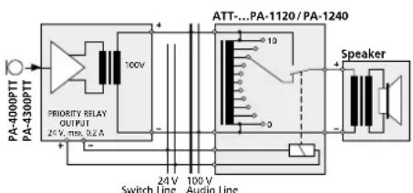
text_image
PA-400PTT PA-430PTT PRIORITY RELAY OUTPUT 24 V, max. 0.2 A ATT...PA-1120 / PA-1240 10V Switch Line Audio Line Speaker⑥ Emergency priority relays
6.10 Switch for (automatic) announcements in all zones
For remote control of the following functions, connect a switch to the terminals MESSAGE FIRST PRIORITY (33).
- All PA zones are switched on and set to maximum volume [like button ALL CALL (6)].
- When the digital message insertion PA-1120DMT is used, the announcement of storage M 6 is automatically called up. For this purpose, set the jumper MS 2 to position PRI prior to installing the insertion (see layout diagram on page 43). Thus, the announcement of storage M 6 takes first priority. Instead of the switch, an alarm contact may be connected, e.g. for an automatic fire alarm announcement.
- If the amplifier is to be switched on simultaneously via the switch or the alarm contact, insert a diode of type 1N4004 between the upper terminal MESSAGE FIRST PRIORITY and the right terminal POWER REMOTE according to fig. 7.
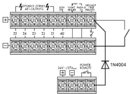
text_image
SPAKER ZONES AT-OUTPUTS BOW INR HIGH PAGING INR KRELASE FAST 4Ω Z5 Z4 Z3 Z2 Z1 1N4004 POWER REMOTE 24V/27A###⑦ Automatic switching on of the amplifier and activation of the announcement M 6
6.11 Telephone switchboard
From a telephone switchboard, announcements may be reproduced via the PA system.
1) Feed the telephone signal (line level) to the terminals PAGING IN (32).
2) During an announcement, adjust the volume with the control PAGING (15).
Note: Telephone announcements take 3rd priority.
6.12 Switching on/off by remote control
A separate switch allows to switch the amplifier on and off by remote control.
1) Connect the screw terminals POWER REMOTE (31) via a two-pole cable to a single-pole power switch.
2) For switching on/off by remote control, the main switch POWER (24) must not be pressed.
6.13 Power supply and emergency power supply
1) For continuous operation of the amplifier after power failure, connect a 24V emergency power supply unit (e.g. PA-24ESP from MONACOR) to the terminals 24 V= (30). For a cable length of up to 7 m, a cable cross-section of 4 mm ^2 as a minimum is required.
2) Finally connect the supplied mains cable to the mains jack (27) first and then to a mains socket (230V/50Hz).
Note: Even when the amplifier is switched off, it has a low power consumption. Therefore, disconnect the mains plug from the socket and, if necessary, disconnect the emergency power supply unit if the amplifier will not be in operation for a longer time.
7 Defining the Priority of Input Signals
A priority is assigned to all input signals. A signal of higher priority always covers a signal of lower priority if both signals are simultaneously applied to the amplifier. (Signals of the same priority are mixed.) The following table gives a survey and shows possibilities of modification.
| Priority | Signal Condition Modification | ||
| 1 | announcementM 6 from digitalmessage insertionPA-1120DMT | jumper MS 2to PRI | |
| switch at (33)closed | |||
| 2 | desk microphonePA-4000PTTPA-4300PTT | DIP switchPRIORITY (48,53) to ON | switch to OFF= 4^th priority ^2 |
| zone pagingmicrophonePA-6000RC | switch at con- nection moduleto PRIORITY | switch toSLAVE = 4^th priority ^2 | |
| chime — — | |||
| 3 | telephoneswitchboard atterminal (32) | — | — |
| 4 | inputs CH 1,CH 2 and CH 3 | DIP switch (45)to OFF ^1 | DIP switchto ON = 3^rd priority |
| siren — — | |||
| 5 | completioninsertions | jumper MS 2 toSLAVE ^1 | jumper MS 2to PRI = 2^nd priority |
| inputs 4 and 5 — — | |||
| telephone bell ornight bell | — | — | |
- Factory setting
- The desk microphone PA-4000PTT/ PA-4300PTT uses input CH 1, and the zone paging microphone PA-1120RC uses input CH 2. Via the corresponding DIP switch MIC PRIORITY (45), the microphones can also be set to 3^rd priority.
8 Operation
If the amplifier is switched off and the mains voltage or emergency supply voltage is applied, the LED STAND BY (25) lights up.
1) Prior to switching on the amplifier for the first time, set all five input controls LEVEL (8 and 10) and the MASTER control (21) to position "0" for the time being.
2) Switch on the amplifier with the POWER switch (24). The LED STAND BY extinguishes, and the LED AC (23) lights up. In case of power failure and applied emergency power supply, the LED DC lights up instead of the LED AC.
8.1 Adjusting the volume
1) First adjust the desired maximum volume for announcements of highest priority. For this purpose, press the button ALL CALL (6) first. Make the announcement according to the equipment used:
a) In case of a digital message insertion, call up the announcement from the storage M 6 via a switch at the terminals MESSAGE FIRST PRIORITY (33). Set the LEVEL control on the insertion to position 7 approximately.
b) In case of a desk microphone PA-4000PTT or PA-4300PTT, set the corresponding LEVEL control (8) of the input CH 1 to position 7 approximately, and make an announcement.
c) In case of a zone paging microphone PA-1120RC, set the corresponding LEVEL control (8) of the input CH 2 to position 7 approximately, and make an announcement.
d) When a different microphone is used, set the corresponding LEVEL control (8) to position 7 approximately, and make an announcement.
2) During the announcement, adjust the volume with the MASTER control (21). In case of overload, the red LED CLIP of the level indicators (7) lights up. In this case, reduce the volume with the MASTER control.
3) To adjust the volume for normal announcements, unlock the button ALL CALL again. For this purpose, press all buttons (4) of the individual PA zones.
4) Make an announcement as described under step 1) b or d.
Notes:
On PA-4000PTT / PA-4300PTT, set the switch PRIORITY (48, 53) to the upper position. Do not make the announcement via a PA-1120RC; its volume is independent of the zone volume switches (5).
5) Do not change the MASTER control (21), but adjust the desired volume for each zone separately with the corresponding zone attenuators (5) during the announcement.
6) Then adjust the volume for the signals of the other inputs (e.g. background music) with the corresponding LEVEL control (8 or 10).
7) Adjust the sound for each input used with the corresponding controls BASS and TREBLE (9 and 11). Adjust the sound for an insertion module in the compartment (1) with the controls PACK (2 and 3).
8) It may be necessary to readjust the volume of the input signals with the corresponding controls (8 or 10).
9) Set the inputs which are not used to "0" with the corresponding controls.
Note: For the inputs CH 1 to CH 3, the input sensitivity can be adjusted with the controls GAIN (41). If a level control (8) must be turned up very much or almost be closed to obtain the desired volume ratio to the other inputs, modify the input sensitivity with the corresponding control GAIN.
8.2 Activating the PA zones
1) Switch on the zones to be activated with the buttons Z1–Z5 (4). The green LEDs indicate the activated zones.
2) For announcements to all zones, press the button ALL CALL (6). At the same time, the volume of the zones is increased to maximum [corresponds to the adjustment of all zone attenuators (5) to position 6].
8.3 Chime
When the TALK button (51, 58, 67) on the microphone PA-4000PTT, PA-4300PTT or PA-1120RC is actuated, a chime will precede an announcement. When using other microphones, the chime can also be triggered with the button CHIME (12). Adjust the volume of the chime with the LEVEL control (13).
With the jumper MS 1, it is possible to switch between a 2-tone chime and a 4-tone chime, see chapter 5.
8.4 Alarm siren
In case of an alarm, one of the two sirens on the operating panel SIREN can be switched on:
Button "\~" (17) for a wailing tone Button "-" (19) for a steady tone
Adjust the volume of the alarm tone with the LEVEL control (18).
8.5 Desk microphone PA-4000PTT or PA-4300PTT
1) With the microphone PA-4000PT or PA-4300PTT connected, the input CH 1 is no longer available. As the microphone requires phantom power for operation, press the switch PHANTOM POWER (40) of input CH 1.
2) If the chime is to sound prior to an announcement when the TALK button (51, 58) is pressed, set the switch CHIME (47, 52) on the rear side of the microphone to position ON (downwards).
3) Set the switch PRIORITY (48, 53) to position ON
- if the microphone is to take 2^nd priority,
- if all PA zones are to be switched on and to be set to maximum volume when the TALK button is pressed [like button ALL CALL (6)],
- if the emergency priority relays are to respond (see chapter 6.9).
4) For an announcement, keep the TALK button (51, 58) pressed and wait for the chime, if required. The green LED lights up as long as the TALK button is pressed.
5) When two or three microphones PA-4300PTT are connected, the switch MASTER/SLAVE (54) can be used to define different priorities for the microphones:
SLAVE other microphones set to MASTER will take priority
MASTER the microphone will take priority over microphones set to SLAVE
The red LED BUSY above the TALK button lights up when another PA-4300PTT with the switch MASTER/SLAVE set to the position MASTER is used for making announcements.
8.6 Zone paging microphone PA-1120RC
1) With the buttons SPEAKER ZONES SELECTOR (69), first switch on the PA zones in which the announcement is to be heard, otherwise no announcement will be possible. To activate all zones, press the button ALL CALL (70).
2) For the announcement, keep the TALK button (67) pressed. The amplifier activates the PA zones according to the preselection under item 1) independent of the adjustments at the amplifier and increases the volume in the zones to maximum [corresponds to the adjustment of all zone volume switches (5) to position 6]. After the chime, make the announcement.
3) When using the digital message insertion PA-1120DMT, a stored announcement may also be called up via the zone paging microphone if the switch DIGITAL MESSAGE (59) is set to position ON:
a) Select the stored announcement with the selector switch MESSAGE BANK (68).
b) Start the announcement with the button START/ STOP (72). To stop the announcement, press the button START/ STOP again.
c) With the button REPEAT/ STOP (71), an announcement can also be repeated several times. Adjust the number of repeats and the intervals on the insertion (see instructions of this insertion). To stop the announcement, actuate the button REPEAT/ STOP again.
Notes:
- The announcement of storage M 6 may be locked (see chapter 6.4.1, item 9). If the switch MESSAGE BANK is set to position 6 in this case, the announcement selected before is reproduced.
- If at least one zone button (4) is pressed at the amplifier, after releasing the TALK button, the announcement selected with the switch MESSAGE BANK can be heard. To prevent this, leave a storage location of the digital message insertion open or cancel it and select this storage location with the switch MESSAGE BANK.
4) The three LEDs POWER, SEND and BUSY (66) give the following information:
POWER lights up when the amplifier is switched on
SEND lights up when an announcement is made via the microphone or a stored announcement is called up
BUSY lights up with individual announcements and with announcements via other connected microphones PA-1120RC.
9 Protective Circuit
The amplifier is provided with a protective circuit against overload and overheating. If the protective circuit is activated, the LED PROT (22) lights up and the amplifier is muted:
- for approx. 1 second after switching on (switch-on delay)
- for approx. 1 second after switching off
- if the amplifier is overloaded
- if the amplifier is overheated; in addition, the LED TEMP (20) lights up
If the LED PROT lights up during operation or if it does not extinguish after switching on, switch off the amplifier and eliminate the source of error.
10 Specifications
| Model | PA-1120 | PA-1240 |
| Output power | ||
| Rated power100V outputs* | 5 × 100W, however together not more than 120 W | 5 × 100W, however together not more than 240 W |
| 4Ω outputs* | 1 × 120W | 1 × 240W |
| Max. output power | 170W | 340W |
| THD | < 1 % | < 1 % |
| Inputs | Input sensitivity, impedance; connection | |
| MIC/LINE CH1-CH3 | 2.5-300mV, 5kΩ; XLR/6.3mm jack, bal. | |
| LINE CH 4 and CH 5 | 300mV, 15kΩ; RCA, unbal. | |
| AMP IN | 775mV, 10kΩ; 6.3 mm jack, unbal. | |
| TEL PAGING | 250mV, 5kΩ; screw connection, bal. | |
| Extension insertion | 250mV, 10kΩ, unbal. | |
| Phantom power | 17V for CH1-3, to be switched individually | |
| Outputs | ||
| Speakers* | 5 × 100V, 1 × 4Ω | |
| REC | 775mV at 3kΩ, unbal. | |
| PRE OUT | 775mV at 100Ω, unbal. | |
| Frequency range | 55-16000 Hz, -3 dB | |
| Equalizer | ||
| Bass | ±10dB/100Hz | |
| Treble | ±10dB/10kHz | |
| S/N ratio | ||
| Line | >80dB (A weighted) | |
| Mic | >70dB (A weighted) | |
| Ambient temperature | 0-40°C | |
| Power supply | ||
| Mains voltage | 230V/50Hz | 230V/50Hz |
| Power consumption | 340VA | 630VA |
| Emergency power supply: | -24V | -24V |
| Direct current consumption | 15A | 27A |
| Dimensions (W × H × D) | 482 × 133 × 352mm | 482 × 133 × 352mm |
| Rack spaces | 3RS | 3RS |
| Weight | 13kg | 14kg |
* Either use the 100 V outputs or the 4Ω output!
Subject to technical modification.
8.6 Micro commande PA-1120RC ..... 21
9 Circuit de protection ..... 21