
LVF 77 IT - Dishwasher FAGOR - Free user manual and instructions
Find the device manual for free LVF 77 IT FAGOR in PDF.
| Product Type | Built-in dishwasher |
| Brand | Fagor |
| Model | LVF 77 IT |
| Built-in dimensions (W x H x D) | 600 x 820-890 x 550 mm |
| Weight (approx.) | 45 kg |
| Supply voltage | 230 V / 50 Hz |
| Minimum circuit current | 10 A |
| Water pressure | 1 to 10 bar (0.1 - 1 MPa) |
| Water flow rate | 10 l/min (min 1 l/min) |
| Water inlet hose length | 1.50 m |
| Capacity (approx.) | 12 place settings |
| Wash programs | Several programs including eco, intensive, quick |
| Additional functions | Delayed start, half load |
| Child safety | Yes |
| Leak protection | Yes (hose with electrical anti-leak device) |
| Maintenance and cleaning | Regular cleaning of filters and spray arms |
| Spare parts and repairability | Spare parts available (seals, adjustment key, etc.); repair by authorized after-sales service |
| General information | User and installation manual provided; compatible with hot water up to 60°C |
Frequently Asked Questions - LVF 77 IT FAGOR
User questions about LVF 77 IT FAGOR
0 question about this device. Answer the ones you know or ask your own.
Ask a new question about this device
Download the instructions for your Dishwasher in PDF format for free! Find your manual LVF 77 IT - FAGOR and take your electronic device back in hand. On this page are published all the documents necessary for the use of your device. LVF 77 IT by FAGOR.
USER MANUAL LVF 77 IT FAGOR
ES MANUAL DE INSTALACIÓN
PT MANUAL DE INSTALAÇÃO
EN INSTALLATIONS MANUAL
FR GUIDE D'INSTALLATION
DE INSTALLATIONSANWEISUNG
NL INSTALLATIEGIDS
CS NÁVOD K INSTALACI
SK INŠTALAČNA PRÍRUČKA
HU TELEPÍTÉSI ÚTMUTATÓ

natural_image
Icon of a closed folder inside a circle (no text or symbols)natural_image
Diagram of a device with a cup and two labeled ports, connected by lines to a container (no text or symbols present)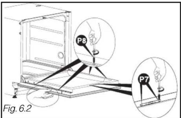
natural_image
Diagram of a device with a cup and lever system, labeled Fig. 3.3 (no text or symbols on the diagram itself)• NIVELAMENTO PELO AJUSTE DOS PÉS
• TABELA PARA O CORTE DO RODAPÉ
| Altura do corte P = | ||||||||||||||
| B_J\E | 10 | 15 | 20 | 25 | 30-75 | 80 | 85 | 90 | 95 | 100 | 105 | 110 | 115 | |
| 170 | 46 | 49 | 51 | 52 | 54 | 52 | 50 | 47 | 44 | 41 | 36 | 30 | 23 | |
| 165 | 42 | 45 | 47 | 48 | 50 | 48 | 46 | 43 | 40 | 37 | 32 | 27 | 20 | |
| 160 | 39 | 41 | 43 | 45 | 46 | 44 | 42 | 40 | 37 | 33 | 29 | 24 | 17 | |
| 155 | 35 | 38 | 40 | 41 | 43 | 40 | 39 | 36 | 34 | 30 | 26 | 21 | 15 | |
| 150 | 32 | 35 | 37 | 38 | 40 | 37 | 36 | 34 | 31 | 28 | 24 | 19 | 13 | |
| 145 | 30 | 32 | 34 | 36 | 37 | 35 | 33 | 31 | 29 | 25 | 22 | 17 | 12 | |
| 140 | 28 | 30 | 32 | 33 | 35 | 32 | 31 | 29 | 26 | 23 | 20 | 16 | 11 | |
| 135 | 26 | 28 | 30 | 31 | 32 | 30 | 29 | 27 | 24 | 22 | 18 | 14 | 10 | |
| 130 | 24 | 26 | 28 | 29 | 30 | 28 | 27 | 25 | 23 | 20 | 17 | 13 | 9 | |
| 125 | 23 | 24 | 26 | 27 | 29 | 27 | 25 | 23 | 21 | 19 | 16 | 12 | 8 | |
| 120 | 21 | 23 | 25 | 26 | 27 | 25 | 24 | 22 | 20 | 18 | 15 | 11 | 8 | |
| 115 | 20 | 22 | 23 | 24 | 26 | 24 | 22 | 21 | 19 | 17 | 14 | 11 | 7 | |
| 110 | 19 | 21 | 22 | 23 | 24 | 22 | 21 | 20 | 18 | 16 | 13 | 10 | 7 | |
| 105 | 18 | 20 | 21 | 22 | 23 | 21 | 20 | 19 | 17 | 15 | 12 | 10 | 6 | |
| 100 | 17 | 19 | 20 | 21 | 22 | 20 | 19 | 18 | 16 | 14 | 12 | 9 | 6 | |
| 95 | 16 | 18 | 19 | 20 | 21 | 19 | 18 | 17 | 15 | 13 | 11 | 9 | 6 | |
| 90 | 16 | 17 | 18 | 19 | 20 | 18 | 17 | 16 | 15 | 13 | 11 | 8 | 6 | |
| 85 | 15 | 16 | 17 | 18 | 19 | 18 | 17 | 15 | 14 | 12 | 10 | 8 | 5 | |
| 80 | 14 | 15 | 17 | 17 | 18 | 17 | 16 | 15 | 13 | 12 | 10 | 8 | 5 | |
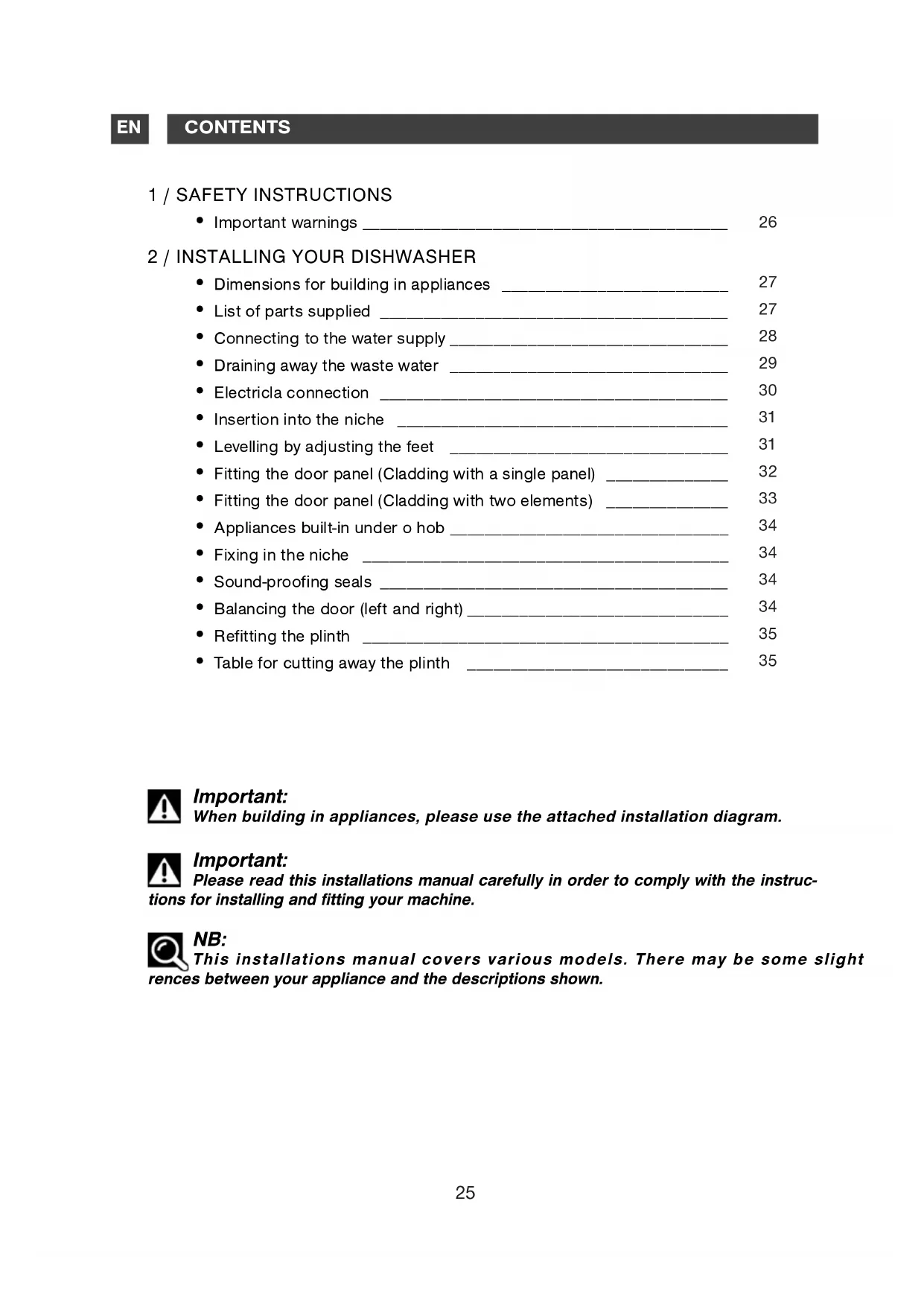
1 / SAFETY INSTRUCTIONS
- Important warnings ____ 26
2 / INSTALLING YOUR DISHWASHER
- Dimensions for building in appliances 27
- List of parts supplied 27
- Connecting to the water supply ____ 28
- Draining away the waste water ____ 29
- Electricla connection 30
- Insertion into the niche ____ 31
- Levelling by adjusting the feet ____ 31
- Fitting the door panel (Cladding with a single panel) ____ 32
- Fitting the door panel (Cladding with two elements) ____ 33
- Appliances built-in under o hob ____ 34
- Fixing in the niche 34
- Sound-proofing seals 34
- Balancing the door (left and right) ____ 34
- Refitting the plinth 35
- Table for cutting away the plinth ____ 35

Important:
When building in appliances, please use the attached installation diagram.

Important:
Please read this installations manual carefully in order to comply with the instruc- for installing and fitting your machine.

NB:
This installations manual covers various models. There may be some slight issues between your appliance and the descriptions shown.
• IMPORTANT WARNINGS

Important:
After unpacking your appliance, make sure that it has not suffered any damage during transport. Never connect up a damaged appliance. If your appliance is damaged, please contact your dealer.

Danger:
If your appliance operates incorrectly, disconnect it (pull out the plug) or switch off the circuit concerned and close the water supply tap. Contact our After-Sales Service.

Important:
All the necessary electrical and plumbing work for installing the appliance must respectively be carried out by a qualified electrician and plumber.
- Once you have installed your appliance, ensure that it is not resting on the power cable or the water supply or drain hoses.
– The appliance must be kept disconnected from the mains supply throughout the whole installation process. - Check that your appliance's Earth circuit complies with the prevailing regulations.
- The electrical connection details on the manufacturer's plate on your machine must match those for the mains power supply.

Important:
For safety's sake, do not leave your dishwasher's door fully open after use.
If your dishwasher is being installed on a carpeted floor, ensure that the feet are set to leave an air space under the appliance.
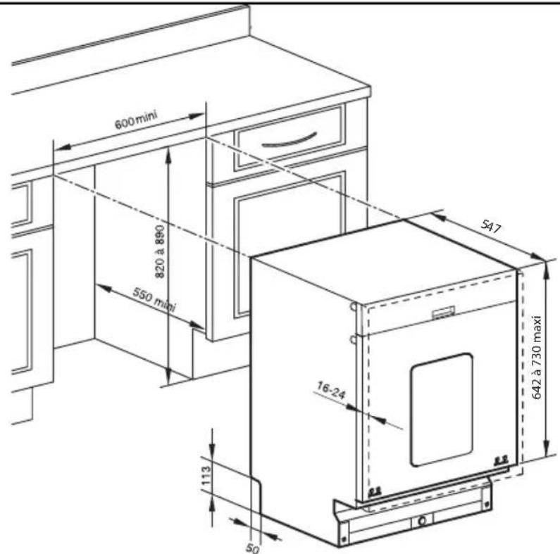
• DIMENSIONS FOR BUILDING IN APPLIANCES
You can insert your appliance under an existing worktop provided that the relevant niche corresponds to the dimensions on the sketch below (Fig. 01).
| P1 | 3 |  Cups for front feet Cups for front feet |
| P2 | 1 | 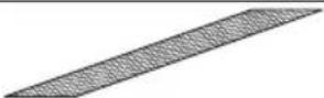 Self-adhesive anti-condensation plate Self-adhesive anti-condensation plate |
| P3 | 1 | 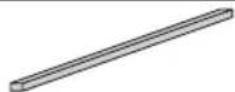 Foam sound-proofing seal Foam sound-proofing seal |
| P4 | 1 | 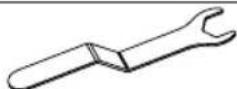 Wrench for adjusting the front feet Wrench for adjusting the front feet |
| P5 | 2 | 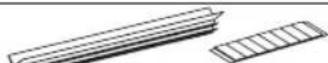 Sound-proofing seals + self-adhesive fixing strips (if necessary) Sound-proofing seals + self-adhesive fixing strips (if necessary) |
| P6 | 2 | 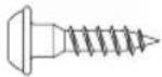 Lower panel positioning screws Lower panel positioning screws |
| P7 | 2 | 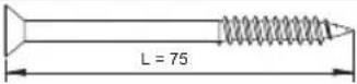 Panel fixing screws Panel fixing screws |
| P8 | 6 | 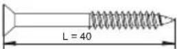 Panel fixing screws Panel fixing screws |
| P9 | 2 | 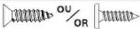 Screws for fixing the appliance to the unit Screws for fixing the appliance to the unit |
| P10 | 1 | Drain connection collar |
| P11 | 1 | 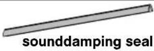 |
• CONNECTING TO THE WATER SUPPLY
This dishwasher can be supplied with cold water or hot water up to a maximum of 60^ C. When supplying with hot water, check that your original hose allows such connection (red marking on the hose). However, we recommend that you connect to the cold water supply. Your appliance is fitted with a supply hose 1.50m long.
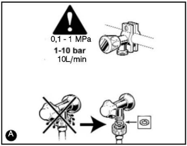
Connect the hose to a tap with a threaded end, diameter 20/27 (3/4" BSP).
Check that the water pressure does not exceed the values below:
Flow rate: 10 ~L / min (1 L/min minimum)
Pressure: 1 to 10 bars (0.1 - 1 MPa) A
If the water pressure is too high, please fit a pressure regulator. Please contact your local Water Authority for advice on the water pressure in your region.

Warning:
If you use a self-piercing tap, check here is sufficient water flow.
Check that the hose seal is present and that the connection is tight Ⓐ.
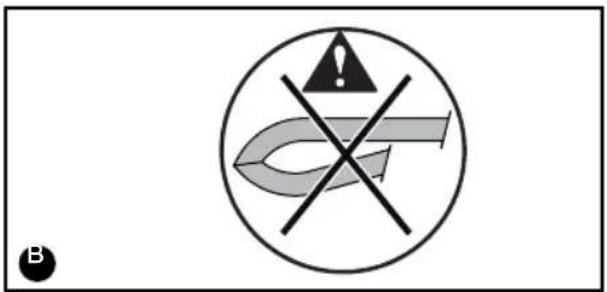
Do not re-use any previously used hoses for making the connection.
Avoid any kinks or constrictions in the hose, which could prevent the water from passing or slow down its flow, particularly when building in the appliance under the worktop B. If the appliance is connected to new pipes or pipes that have not been used for a certain length of time, let the water run for a few minutes before connecting the water hose to avoid and deposits of sand or rust that could block the water hose's filter.

Danger:

symbol indicates that
the hose is fitted with an electrical device for cutting off the water supply (depending on the model). Do not leave this hose in water and do not cut it.

NB:
Any connection to a water conduit necessarily involves the risk of a leak occurring, whatever the precautions taken. Therefore, always close the water tap when you are not using your machine.
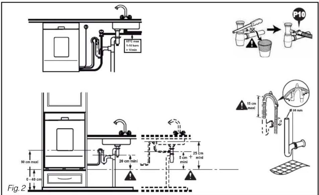
• DRAINING AWAY THE WASTE WATER: FIG. 2
You can connect the end of the drain hose to:
- A ventilated U-bend or
- A sink U-bend
If necessary, you can increase the hose' length (up to 3m maximum). In this case check that the appliance drains correctly. The hose must rest on the floor and only rise vertically close to the drainage system.
When connecting to a U-bend, you must remove the flapper from the U-bend. Then fully install the rubber end. If necessary, add a tightening co
For appliances installed in vertical drainage system must not rise high than the top of the appliance.

NB:
Ensure that the drain hose place with a tie to avoid any potential flooding.
The drain connection must be 0.40m (minimum) to 0.90m (maximum) above the floor.

Important:
When fitting the hose, pull on it gradually so as not to kink it.
Avoid any kinks or constriction hose, which could prevent the water from passing or slow down its flow.
Make sure that you adhere to the maximum dimensions for the fitting of the drainage tube in the siphon pipe
The appliance must be at a standstill when connecting to the electricity supply circuit.
Before connecting your appliance, ensure that:
- The mains voltage indicated on the manufacturer's plate on your machine matches the voltage supplied by your installation.
- Your meter and the fuses can support the current intensity for your dishwasher. A fuse of at least 10A is required.
If you must connect your appliance to a different voltage from that indicated on your machine, connect an appropriate transformer.

NB:
Use the services of a qualified electrician to make the modifications and ensure that your electrical installation complies with the regulations.
This appliance must necessarily be connected directly to an earthed plug and socket.
In all cases, it must be connected in accordance with the prevailing regulations in the country concerned and any additional regulations from the local electricity utility.

Warning:
The plug and socket must be accessible even after your appliance has been installed.
The appliance must not be connected via an extension lead, a multiple socket or an electric time delay programmer Ⓐ.
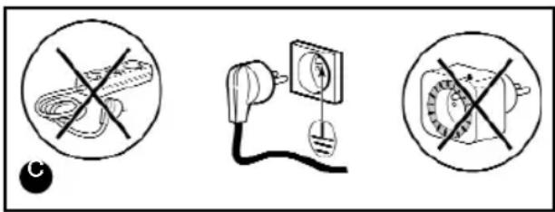
We cannot be held responsible in the event of an accident or an incident caused by the lack of or by a defective Earthing system.
Your dishwasher complies with European Directives 73/23/EEC (Low Voltage Directive) and 89/336/EEC (Electromagnetic Compatibility) as modified by Directive 93/68/EEC.
- Replacing the power cable

Danger:
For your safety's sake, this operation must only be performed by the manufacturer's After-Sales Department or by someone with similar qualifications in order to avoid any risks.
• Appliances delivered without a plug

Danger:
The wires in your appliance's power cable are coloured as follows:
- Green & Yellow
Earth
- Blue
Neutral
- Brown Live
If the cable's colours do not match your plug, proceed as follows:
The wire coloured green and yellow must be connected to the connector in your plug marked with the letter E, the symbol 1· or coloured green and yellow.
The blue-coloured wire must be connected to the connector marked with the letter N or coloured black.
The brown-coloured wire must be connected to the connector marked with the letter L or coloured red.
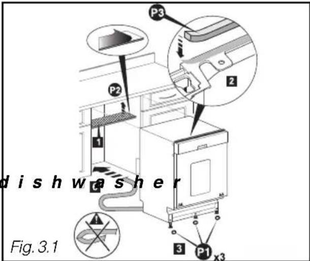
- INSERTION INTO THE NICHE
- Glue on the anti-condensation plate (Fig. 3.1)
- Glue on the foam sound-proofing seal (Fig. 3.1)
- Clip the three cup under the feet to make the easier to slide (Fig. 3.1).
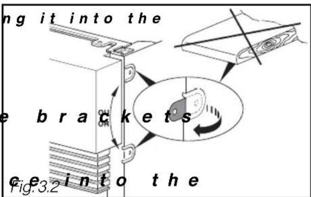
If the worktop is in marble or a similar material, you must fix your dishwasher using the side screws; before inserti niche, you must therefore unfold a flange on each side of the side panels (Fig. 3.2).
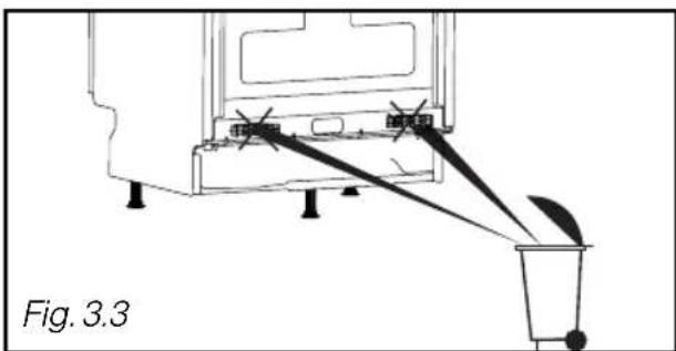
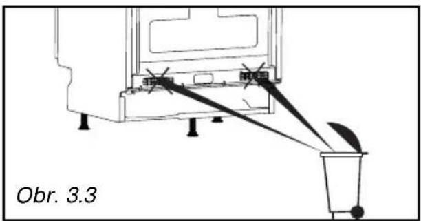
- Remove the hose (Fig. 3.3)
• Slide the applian niche, TAKING SPECIAL CARE NOT TO KINK THE HOSES.
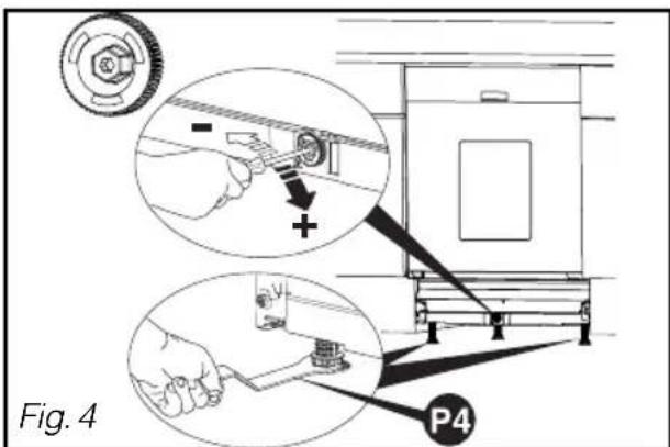
The front feet are adjustable. Use the wrench provided to adjust them, if necessary.
The central foot can be adjusted using the red wheel (screwdriver with No. 8 plug, No. 8 pipe wrench or T20 Torx screwdriver).
The appliance must be correctly levelled so that the door closes and seals perfectly (Fig. 4).
Ensure that the dishwasher's door closes correctly, without catching or rubbing against the sides.
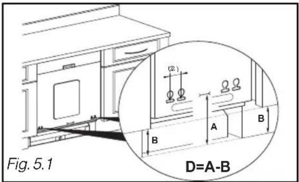
• FITTING THE DOOR PANEL (Cladding with a single panel)
- Measure the distance between the floor and the bottom of the door panel on the adjacent unit (Dimension B, Fig. 5.1)
- Measure the distance between the floor and the marking on the bottom of the door panel (Dimension A)
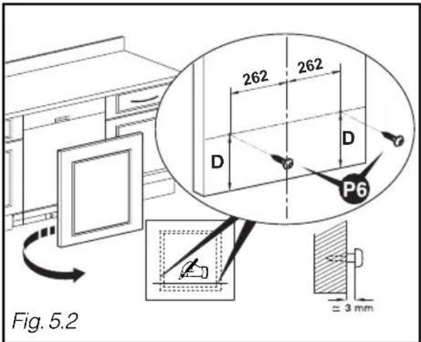
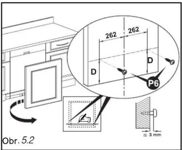
- Calculate Dimension D = A - B, and draw a line for Dimension D on the back of the panel at the bottom (Fig. 5.2)
- Set the positions for the two screws at 262mm from the wood panel's axis and insert two screws P6. (Fig. 5.2)
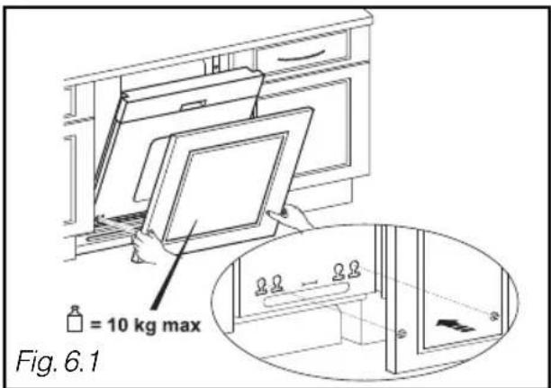
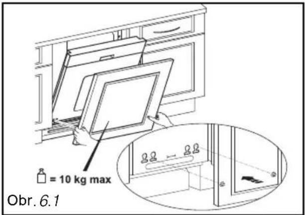
- Position your door panel by engaging the 2 screws in the holes in the dishwasher's door (Fig. 6.1)
- If there is a problem with screwing, offset the screw P6 by 22 mm.
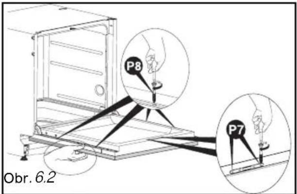
- Place the wood panel flat against the door (Fig. 6.2).
- Open the dishwasher's door while holding the panel flat up against the door. Centre the wood panel at the sides with respect to the control panel, if necessary. Insert the 2 screws P7 and the 4 screws P8 (Fig. 6.2).

Warning :
If the wood panel is very hard, ensure that you make a hole in advance before screwing the panel on.

NB :
If your appliance is supplied with a sound insulation sheet, glue this on before installing the door panel.

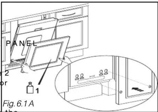
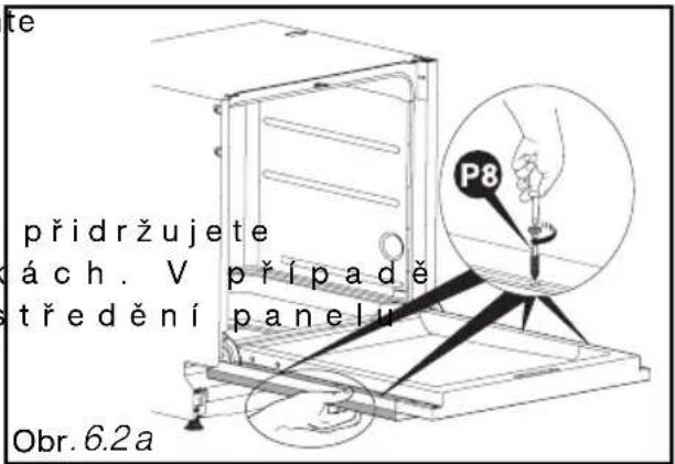
FITTING THE DOOR PANEL (Cladding with 2 elements)
- To fit the first section, please refer to the previous chapter "FITTING THE DOOR (Cladding with a single panel) (Figs. 5.1 et 5.2).
- Position your door panel by engaging the 2 screws in the holes in the dishwasher's door (Fig. 6.2 A)
- If there is any difficulty screwing, move the s c P6 r e w 2 2 mm.
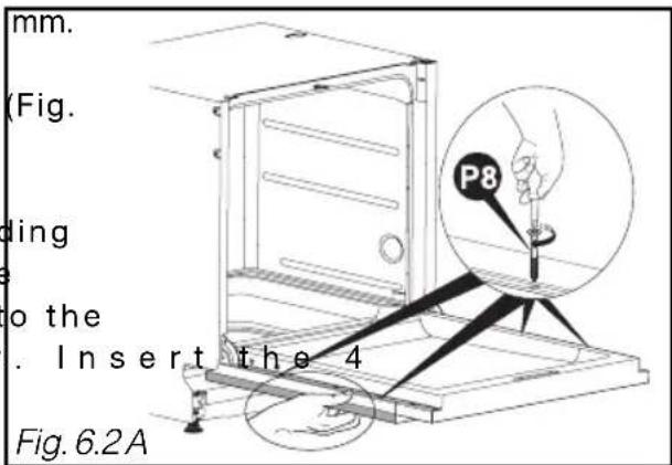
- Place the wood panel flat against the door (Fig. 6.2 A).
- Open the dishwasher's door while holding the panel flat up against the door. Centre the wood panel at the sides with respect to the control panel, if necessary. In screws (P8) fig. 6.2 A).
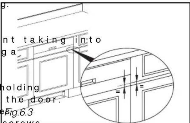
- Measure the distance between the drawer and the door panel on the adjacent unit (Fig. 6.3).
- Place the false drawer front account the distance just measured (using a wedge with a good thickness).
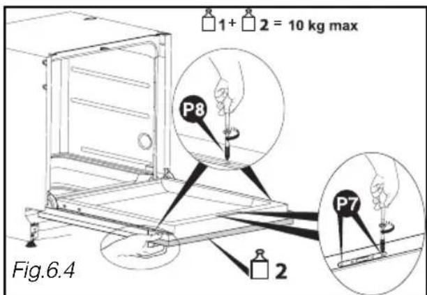
- Open the dishwasher's door while holding the false drawer front up against the dc Centre the wood panel at the sides with reFig.6.3 pect to the door panel. Insert the 2 screws
● and the 2 screws (P8)ig. 6.4).

Warning :
If the wood panel is very hard, ensure that you make an initial hole before screwing it on.

Warning :
Then total weight of the door panel and the false drawer front must not exceed 10kg maximum.
• APPLIANCES BUILT-IN UNDER A HOB

Danger:
If your worktop has a hob fitted above your dishwasher, you must fit thermal insulation on top of your dishwasher. You can obtain an insulation kit from your dealer. Remember to leave a space between the gas pipe and the top of your dishwasher.
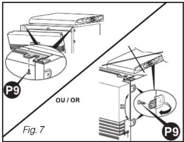
• FIXING IN THE NICHE
Fasten the dishwasher under the worktop with the screws P9 (see Fig. 7) or using the flanges you have unfolded (Fig. 3.2).

Warning:
The screw provided is intended for a panel at least 16mm thick. If the panel is less than 16mm thick, change the screw or shorten it.
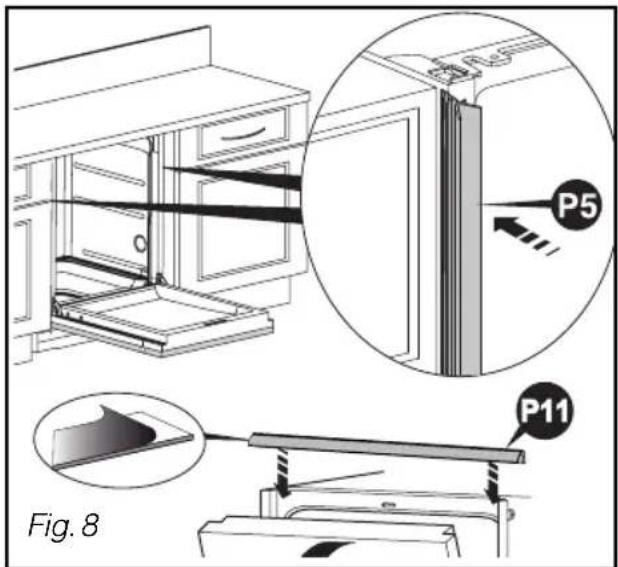
• SOUND-PROOFING SEALS
To improve the built-in appliance's sound-proofing, fit the sound-proofing seals (depending on the model). (P5 P11 on Fig. 8)
If the recess is bigger, stick on seal P5 using the adhesives provided.
If the appliance is laterally secured, a cut must be made in the seals' P5 heels to allow the retaining brackets to be passed through (nipper).
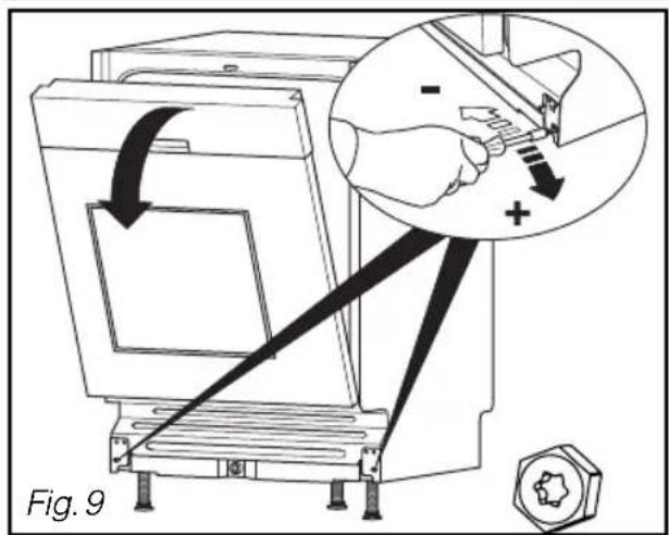
• BALANCING THE DOOR (LEFT AND RIGHT)
Adjust the tension on the springs, if necessary, to compensate for the weight of the cladding panel. Adjust them identically on the right and the left (Fig. 9).
The door is correctly balanced when it dopes not fall heavily on opening and it remains horizontal in the open position.
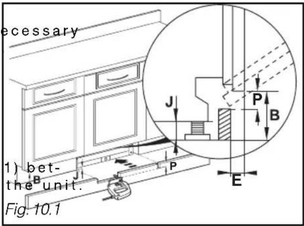
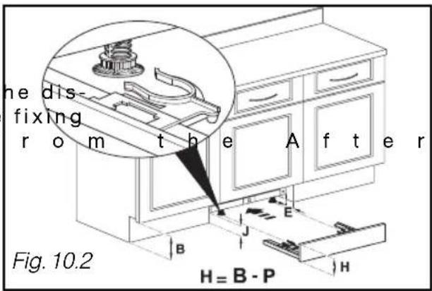
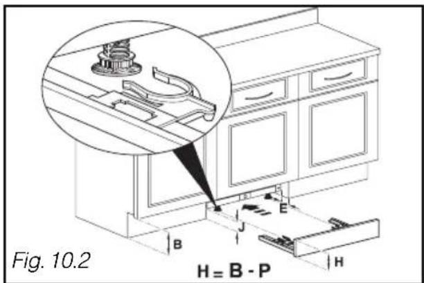
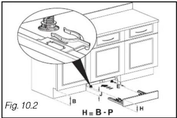
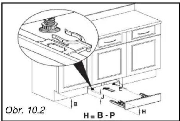
• REFITTING THE PLINTH
Refit the plinth, cutting it away if no according to Dimension P (see table and Fig 10.1)
Calculate dimension P (Table on last page): - Take Dimension B from Fig. 6.1 and measure the gap J between the floor and the bottom of the dishwasher. Calculate B - J.
- Measure the plinth depth E (Fig. 10, ween the unit's plinth and front of Take the value for P from the table provided by E and B - J (e.g. if E = 100 and B - J = 140, then P = 23).
- Cut away the plinth across a width of 600mm to the depth for the value for P.
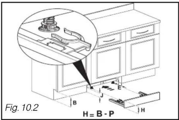
If there will be a specific plinth for t hwasher, you must obtain a separate k i t (3 2 X 3 2 5 2) f Department. In this case, the plinth height is H = B - P (Fig. 10.2).
• TABLE FOR CUTTING AWAY THE PLINTH
| Cut-away depth P = | |||||||||||||
| B.J\E | 10 | 15 | 20 | 25 | 30-75 | 80 | 85 | 90 | 95 | 100 | 105 | 110 | 115 |
| 170 | 46 | 49 | 51 | 52 | 54 | 52 | 50 | 47 | 44 | 41 | 36 | 30 | 23 |
| 165 | 42 | 45 | 47 | 48 | 50 | 48 | 46 | 43 | 40 | 37 | 32 | 27 | 20 |
| 160 | 39 | 41 | 43 | 45 | 46 | 44 | 42 | 40 | 37 | 33 | 29 | 24 | 17 |
| 155 | 35 | 38 | 40 | 41 | 43 | 40 | 39 | 36 | 34 | 30 | 26 | 21 | 15 |
| 150 | 32 | 35 | 37 | 38 | 40 | 37 | 36 | 34 | 31 | 28 | 24 | 19 | 13 |
| 145 | 30 | 32 | 34 | 36 | 37 | 35 | 33 | 31 | 29 | 25 | 22 | 17 | 12 |
| 140 | 28 | 30 | 32 | 33 | 35 | 32 | 31 | 29 | 26 | 23 | 20 | 16 | 11 |
| 135 | 26 | 28 | 30 | 31 | 32 | 30 | 29 | 27 | 24 | 22 | 18 | 14 | 10 |
| 130 | 24 | 26 | 28 | 29 | 30 | 28 | 27 | 25 | 23 | 20 | 17 | 13 | 9 |
| 125 | 23 | 24 | 26 | 27 | 29 | 27 | 25 | 23 | 21 | 19 | 16 | 12 | 8 |
| 120 | 21 | 23 | 25 | 26 | 27 | 25 | 24 | 22 | 20 | 18 | 15 | 11 | 8 |
| 115 | 20 | 22 | 23 | 24 | 26 | 24 | 22 | 21 | 19 | 17 | 14 | 11 | 7 |
| 110 | 19 | 21 | 22 | 23 | 24 | 22 | 21 | 20 | 18 | 16 | 13 | 10 | 7 |
| 105 | 18 | 20 | 21 | 22 | 23 | 21 | 20 | 19 | 17 | 15 | 12 | 10 | 6 |
| 100 | 17 | 19 | 20 | 21 | 22 | 20 | 19 | 18 | 16 | 14 | 12 | 9 | 6 |
| 95 | 16 | 18 | 19 | 20 | 21 | 19 | 18 | 17 | 15 | 13 | 11 | 9 | 6 |
| 90 | 16 | 17 | 18 | 19 | 20 | 18 | 17 | 16 | 15 | 13 | 11 | 8 | 6 |
| 85 | 15 | 16 | 17 | 18 | 19 | 18 | 17 | 15 | 14 | 12 | 10 | 8 | 5 |
| 80 | 14 | 15 | 17 | 17 | 18 | 17 | 16 | 15 | 13 | 12 | 10 | 8 | 5 |
1 / CONSIGNES DE SECURITE
- Avertissements importants 37
2 / INSTALLATION DE VOTRE LAVE-VAISSELLE
• TABLEAU POUR DECOUPE DE LA PLINTHE
| Hauteur de découpe P = | |||||||||||||
| B_J\E | 10 | 15 | 20 | 25 | 30-75 | 80 | 85 | 90 | 95 | 100 | 105 | 110 | 115 |
| 170 | 46 | 49 | 51 | 52 | 54 | 52 | 50 | 47 | 44 | 41 | 36 | 30 | 23 |
| 165 | 42 | 45 | 47 | 48 | 50 | 48 | 46 | 43 | 40 | 37 | 32 | 27 | 20 |
| 160 | 39 | 41 | 43 | 45 | 46 | 44 | 42 | 40 | 37 | 33 | 29 | 24 | 17 |
| 155 | 35 | 38 | 40 | 41 | 43 | 40 | 39 | 36 | 34 | 30 | 26 | 21 | 15 |
| 150 | 32 | 35 | 37 | 38 | 40 | 37 | 36 | 34 | 31 | 28 | 24 | 19 | 13 |
| 145 | 30 | 32 | 34 | 36 | 37 | 35 | 33 | 31 | 29 | 25 | 22 | 17 | 12 |
| 140 | 28 | 30 | 32 | 33 | 35 | 32 | 31 | 29 | 26 | 23 | 20 | 16 | 11 |
| 135 | 26 | 28 | 30 | 31 | 32 | 30 | 29 | 27 | 24 | 22 | 18 | 14 | 10 |
| 130 | 24 | 26 | 28 | 29 | 30 | 28 | 27 | 25 | 23 | 20 | 17 | 13 | 9 |
| 125 | 23 | 24 | 26 | 27 | 29 | 27 | 25 | 23 | 21 | 19 | 16 | 12 | 8 |
| 120 | 21 | 23 | 25 | 26 | 27 | 25 | 24 | 22 | 20 | 18 | 15 | 11 | 8 |
| 115 | 20 | 22 | 23 | 24 | 26 | 24 | 22 | 21 | 19 | 17 | 14 | 11 | 7 |
| 110 | 19 | 21 | 22 | 23 | 24 | 22 | 21 | 20 | 18 | 16 | 13 | 10 | 7 |
| 105 | 18 | 20 | 21 | 22 | 23 | 21 | 20 | 19 | 17 | 15 | 12 | 10 | 6 |
| 100 | 17 | 19 | 20 | 21 | 22 | 20 | 19 | 18 | 16 | 14 | 12 | 9 | 6 |
| 95 | 16 | 18 | 19 | 20 | 21 | 19 | 18 | 17 | 15 | 13 | 11 | 9 | 6 |
| 90 | 16 | 17 | 18 | 19 | 20 | 18 | 17 | 16 | 15 | 13 | 11 | 8 | 6 |
| 85 | 15 | 16 | 17 | 18 | 19 | 18 | 17 | 15 | 14 | 12 | 10 | 8 | 5 |
| 80 | 14 | 15 | 17 | 17 | 18 | 17 | 16 | 15 | 13 | 12 | 10 | 8 | 5 |
• AFVOER VAN AFVALWATER: FIG. 2
• TABEL VOOR HET OP MAAT BRENGEN VAN DE PLING
| Zaaghoogte P = | |||||||||||||
| B-J E | 10 | 15 | 20 | 25 | 30-75 | 80 | 85 | 90 | 95 | 100 | 105 | 110 | 115 |
| 170 | 46 | 49 | 51 | 52 | 54 | 52 | 50 | 47 | 44 | 41 | 36 | 30 | 23 |
| 165 | 42 | 45 | 47 | 48 | 50 | 48 | 46 | 43 | 40 | 37 | 32 | 27 | 20 |
| 160 | 39 | 41 | 43 | 45 | 46 | 44 | 42 | 40 | 37 | 33 | 29 | 24 | 17 |
| 155 | 35 | 38 | 40 | 41 | 43 | 40 | 39 | 36 | 34 | 30 | 26 | 21 | 15 |
| 150 | 32 | 35 | 37 | 38 | 40 | 37 | 36 | 34 | 31 | 28 | 24 | 19 | 13 |
| 145 | 30 | 32 | 34 | 36 | 37 | 35 | 33 | 31 | 29 | 25 | 22 | 17 | 12 |
| 140 | 28 | 30 | 32 | 33 | 35 | 32 | 31 | 29 | 26 | 23 | 20 | 16 | 11 |
| 135 | 26 | 28 | 30 | 31 | 32 | 30 | 29 | 27 | 24 | 22 | 18 | 14 | 10 |
| 130 | 24 | 26 | 28 | 29 | 30 | 28 | 27 | 25 | 23 | 20 | 17 | 13 | 9 |
| 125 | 23 | 24 | 26 | 27 | 29 | 27 | 25 | 23 | 21 | 19 | 16 | 12 | 8 |
| 120 | 21 | 23 | 25 | 26 | 27 | 25 | 24 | 22 | 20 | 18 | 15 | 11 | 8 |
| 115 | 20 | 22 | 23 | 24 | 26 | 24 | 22 | 21 | 19 | 17 | 14 | 11 | 7 |
| 110 | 19 | 21 | 22 | 23 | 24 | 22 | 21 | 20 | 18 | 16 | 13 | 10 | 7 |
| 105 | 18 | 20 | 21 | 22 | 23 | 21 | 20 | 19 | 17 | 15 | 12 | 10 | 6 |
| 100 | 17 | 19 | 20 | 21 | 22 | 20 | 19 | 18 | 16 | 14 | 12 | 9 | 6 |
| 95 | 16 | 18 | 19 | 20 | 21 | 19 | 18 | 17 | 15 | 13 | 11 | 9 | 6 |
| 90 | 16 | 17 | 18 | 19 | 20 | 18 | 17 | 16 | 15 | 13 | 11 | 8 | 6 |
| 85 | 15 | 16 | 17 | 18 | 19 | 18 | 17 | 15 | 14 | 12 | 10 | 8 | 5 |
| 80 | 14 | 15 | 17 | 17 | 18 | 17 | 16 | 15 | 13 | 12 | 10 | 8 | 5 |
1 / BEZPEČNOSTNÍ POKYNY
• VYROVNANIE POMOCOU NASTAVENIA NOŽIČIEK
• TABUL'KA NA ODREZANIE PODLAHOVEJ LIŠTY
| Výška výrezu P = | |||||||||||||
| B_J\E | 10 | 15 | 20 | 25 | 30-75 | 80 | 85 | 90 | 95 | 100 | 105 | 110 | 115 |
| 170 | 46 | 49 | 51 | 52 | 54 | 52 | 50 | 47 | 44 | 41 | 36 | 30 | 23 |
| 165 | 42 | 45 | 47 | 48 | 50 | 48 | 46 | 43 | 40 | 37 | 32 | 27 | 20 |
| 160 | 39 | 41 | 43 | 45 | 46 | 44 | 42 | 40 | 37 | 33 | 29 | 24 | 17 |
| 155 | 35 | 38 | 40 | 41 | 43 | 40 | 39 | 36 | 34 | 30 | 26 | 21 | 15 |
| 150 | 32 | 35 | 37 | 38 | 40 | 37 | 36 | 34 | 31 | 28 | 24 | 19 | 13 |
| 145 | 30 | 32 | 34 | 36 | 37 | 35 | 33 | 31 | 29 | 25 | 22 | 17 | 12 |
| 140 | 28 | 30 | 32 | 33 | 35 | 32 | 31 | 29 | 26 | 23 | 20 | 16 | 11 |
| 135 | 26 | 28 | 30 | 31 | 32 | 30 | 29 | 27 | 24 | 22 | 18 | 14 | 10 |
| 130 | 24 | 26 | 28 | 29 | 30 | 28 | 27 | 25 | 23 | 20 | 17 | 13 | 9 |
| 125 | 23 | 24 | 26 | 27 | 29 | 27 | 25 | 23 | 21 | 19 | 16 | 12 | 8 |
| 120 | 21 | 23 | 25 | 26 | 27 | 25 | 24 | 22 | 20 | 18 | 15 | 11 | 8 |
| 115 | 20 | 22 | 23 | 24 | 26 | 24 | 22 | 21 | 19 | 17 | 14 | 11 | 7 |
| 110 | 19 | 21 | 22 | 23 | 24 | 22 | 21 | 20 | 18 | 16 | 13 | 10 | 7 |
| 105 | 18 | 20 | 21 | 22 | 23 | 21 | 20 | 19 | 17 | 15 | 12 | 10 | 6 |
| 100 | 17 | 19 | 20 | 21 | 22 | 20 | 19 | 18 | 16 | 14 | 12 | 9 | 6 |
| 95 | 16 | 18 | 19 | 20 | 21 | 19 | 18 | 17 | 15 | 13 | 11 | 9 | 6 |
| 90 | 16 | 17 | 18 | 19 | 20 | 18 | 17 | 16 | 15 | 13 | 11 | 8 | 6 |
| 85 | 15 | 16 | 17 | 18 | 19 | 18 | 17 | 15 | 14 | 12 | 10 | 8 | 5 |
| 80 | 14 | 15 | 17 | 17 | 18 | 17 | 16 | 15 | 13 | 12 | 10 | 8 | 5 |
1 / BIZTONSÁGI TANÁCSOK
• A SZENNYVÍZ ELVEZETÉSE: 2. ÁBRA
• ELHELYEZÉS AZ ÜREGBEN
- • NIVELAMENTO PELO AJUSTE DOS PÉS
- • TABELA PARA O CORTE DO RODAPÉ
- / SAFETY INSTRUCTIONS
- / INSTALLING YOUR DISHWASHER
- Important:
- NB:
- • IMPORTANT WARNINGS
- Danger:
- • DIMENSIONS FOR BUILDING IN APPLIANCES
- • CONNECTING TO THE WATER SUPPLY
- Warning:
- • DRAINING AWAY THE WASTE WATER: FIG. 2
- - Replacing the power cable
- • Appliances delivered without a plug
- - INSERTION INTO THE NICHE
- • FITTING THE DOOR PANEL (Cladding with a single panel)
- Warning :
- NB :
- FITTING THE DOOR PANEL (Cladding with 2 elements)
- • APPLIANCES BUILT-IN UNDER A HOB
- • FIXING IN THE NICHE
- • SOUND-PROOFING SEALS
- • BALANCING THE DOOR (LEFT AND RIGHT)
- • REFITTING THE PLINTH
- • TABLE FOR CUTTING AWAY THE PLINTH
- / CONSIGNES DE SECURITE
- / INSTALLATION DE VOTRE LAVE-VAISSELLE
- • TABLEAU POUR DECOUPE DE LA PLINTHE
- • AFVOER VAN AFVALWATER: FIG. 2
- • TABEL VOOR HET OP MAAT BRENGEN VAN DE PLING
- / BEZPEČNOSTNÍ POKYNY
- • TABUL'KA NA ODREZANIE PODLAHOVEJ LIŠTY
- / BIZTONSÁGI TANÁCSOK
- • A SZENNYVÍZ ELVEZETÉSE: 2. ÁBRA
- • ELHELYEZÉS AZ ÜREGBEN
Brand : FAGOR
Model : LVF 77 IT
Category : Dishwasher