
AX892 - Receiver YAMAHA - Free user manual and instructions
Find the device manual for free AX892 YAMAHA in PDF.
Download the instructions for your Receiver in PDF format for free! Find your manual AX892 - YAMAHA and take your electronic device back in hand. On this page are published all the documents necessary for the use of your device. AX892 by YAMAHA.
USER MANUAL AX892 YAMAHA
After unpacking, check that the following accessories are included. ACCESSOIRES FOURNIS
Batterijen (maat AA, R6, UM-3) WARNING Do not change the IMPEDANCE SELECTOR switch setting while the power to this unit is on, otherwise this unit may be damaged. IF THIS UNIT FAILS TO TURN ON WHEN THE
85W + 85W (8Ω) RMS Output Power, 0.019% THD, 20–20,000 Hz
115W + 115W (8Ω) RMS Output Power, 0.015% THD, 20–20,000 Hz
High Dynamic Power, Low Impedance Drive Capability
Continuously Variable Loudness Control
SUBSONIC FILTER switch; used to eliminate undesirable ultra-low-frequency signals ( AX-592 and AX-892 only
PRE OUT/MAIN IN terminals; useful for connecting an equalizer, sound processor, etc. ( AX-592 and AX-892 only
Remote control capability AX-892AX-592AX-492
1. To assure the finest performance, please read this manual
carefully and keep it in a safe place for future use.
2. Install this unit in a cool, dry and dust-free area. Do not place it in
direct sunlight or near sources of heat (e.g., a stove, etc.). Makesure that it is well ventilated and not exposed to rain or moistureand that it is on a flat, stable surface, free from vibration.
3. Never open the cabinet. If something drops into the unit, contact
4. When moving the unit, first disconnect the AC power plug and the
cables which are connected to other equipment. Never pull thecables or use excessive force on switches or controls.
5. The openings on the cabinet assure proper ventilation of the unit.
If these openings are obstructed, the temperature inside thecabinet will rise rapidly, damaging the unit or causing a fire. Avoidblocking the ventilation openings and make sure that the unit iswell ventilated. Allow at least 30 cm (12 in) of space above theunit and 20 cm (8 in) of space on the sides and rear.
6. Always set the VOLUME control to “
” before playing the source.Increase the volume gradually to a desired level after the sourcehas started playing.
7. Use a clean, dry cloth to clean the unit. Do not use chemical
solvents which might damage the finish.
8. Be sure to read the “TROUBLESHOOTING” section before
deciding that the unit is faulty.
9. When not planning to use this unit for long periods of time (e.g.,
vacation, etc.), disconnect the AC power plug from the electricaloutlet.
10. To prevent damage from lightning, disconnect the AC power plug
and antenna cable when there is an electrical storm.
11. Make sure that the unit is always properly grounded and
12. Do not connect audio equipment to the AC outlet on the rear panel
if the equipment requires more power than the outlet is rated toprovide.
13. Voltage Selector (General Model only)
The voltage selector on the rear panel of this unit must be setfor your local main voltage beforeplugging into the electricaloutlet.Voltages are 110/120/220/240 V AC, 60/50 Hz. WARNING To reduce the risk of fire or electric shock, do not expose the unit torain or moisture. IMPORTANT The serial number is located on the rear panel.Please record the serial number of this unit in the space below.Serial No.:Keep this Owner’s Manual in a safe place for future use. Note The unit is not disconnected from the AC power source as long as itis connected to the electrical outlet, even if the unit itself is turned off. For UK customers If the electrical outlets in the home are not suitable for the plugwhich is supplied with this unit, cut off the plug and attach anappropriate 3-pin plug. Note The removed plug must be destroyed, as a plug with exposed wiresis hazardous if inserted into a live electrical outlet. IMPORTANT The wires in the mains lead are colored as follows:Blue: NeutralBrown: LiveAs the colors of the wires in the mains lead of this apparatus maynot correspond with the colored markings identifying the terminals inyour plug, proceed as follows:The wire which is colored BLUE must be connected to the terminalwhich is marked with the letter N or colored BLACK. The wirewhich is colored BROWN must be connected to the terminal whichis marked with the letter L or colored RED. Make sure that neithercore is connected to the ground terminal of the 3-pin plug. CAUTION: READ THIS BEFORE OPERATING YOUR UNIT. Thank you for selecting this YAMAHA stereo amplifier. CONTENTS FEATURES4 CONNECTIONS
Before making any connections to or from this unit, first switch it and any other connected components off.
Properly connect this unit and other components, L (left) to L, R (right) to R, “+” to “+” and “–” to “–”. Also, refer to the owner’s manual of each component which is to be connected to this unit.
If you have YAMAHA components numbered 1, 2, 3, etc. on the rear panel, connections can easily be made by connecting the output (input) terminals of each component to the same-numbered terminals on this unit.
OUTPUT GND OUTPUT OUTPUT AUDIO OUT LINE OUT LINE IN LINE OUT LINE IN AX-492 Turntable Tape deck 1 Tape deck 2 Speakers A Speakers B Video cassette player, LD player, etc. TunerCompact disc player Right Left Right Left <General model>
- For descriptions of the shaded areas, refer to page 8.5 English
- For descriptions of the shaded areas, refer to page 8.6
LINE OUT OUTPUT OUTPUT AUDIO OUT OUTPUT GND LINE IN LINE OUT LINE IN VOLTAGE SELECTOR AX-892 Turntable Tape deck 1 Tape deck 2 Speakers A Speakers BVideo cassette player, LD player, etc. TunerCompact disc player Right Left Right Left
- For descriptions of the shaded areas, refer to page 8. <General model>7 English
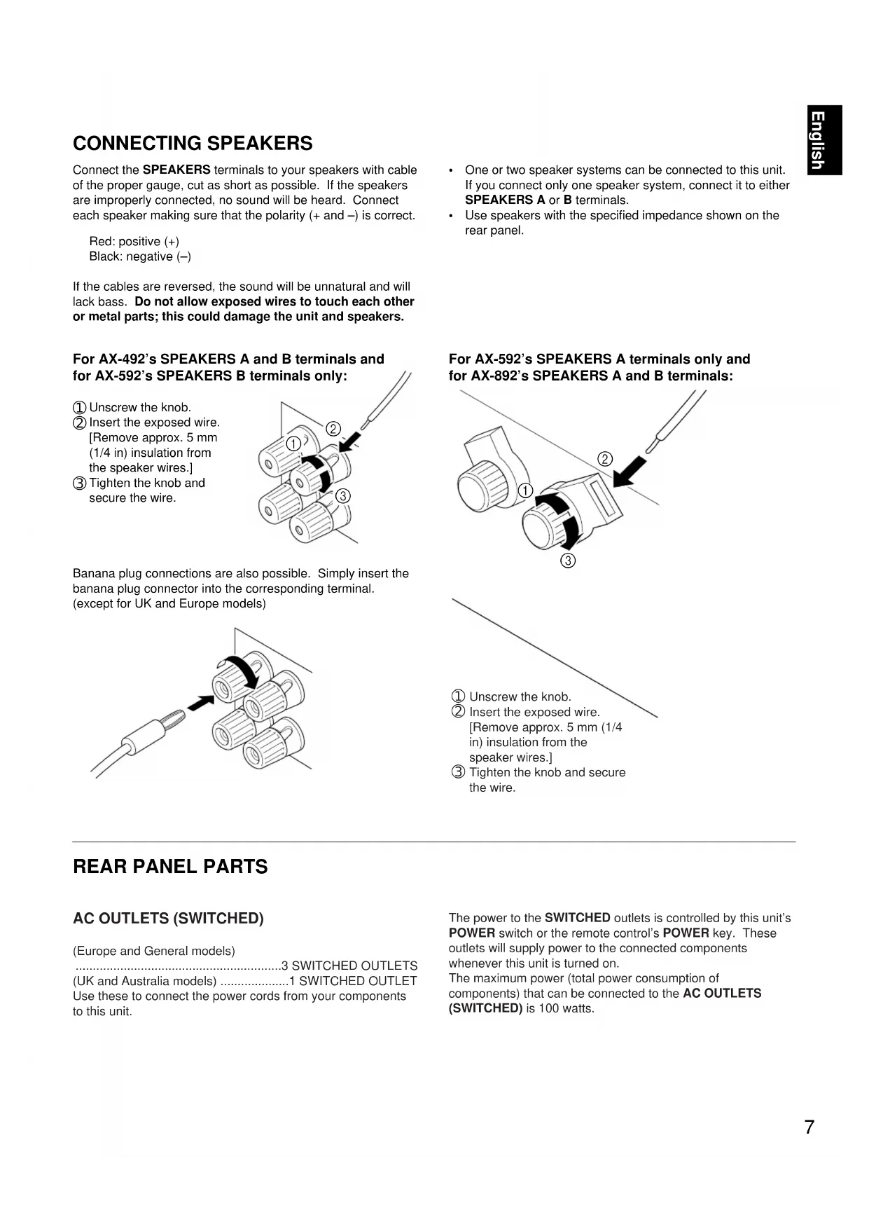
Connect the SPEAKERS terminals to your speakers with cable of the proper gauge, cut as short as possible. If the speakers are improperly connected, no sound will be heard. Connect each speaker making sure that the polarity (+ and –) is correct. Red: positive (+) Black: negative (–) If the cables are reversed, the sound will be unnatural and will lack bass. Do not allow exposed wires to touch each other or metal parts; this could damage the unit and speakers. For AX-492’s SPEAKERS A and B terminals and for AX-592’s SPEAKERS B terminals only:
Insert the exposed wire. [Remove approx. 5 mm (1/4 in) insulation from the speaker wires.]
Tighten the knob and secure the wire. Banana plug connections are also possible. Simply insert the banana plug connector into the corresponding terminal. (except for UK and Europe models)
One or two speaker systems can be connected to this unit. If you connect only one speaker system, connect it to either SPEAKERS A or B terminals.
AC OUTLETS (SWITCHED) (Europe and General models) ............................................................3 SWITCHED OUTLETS (UK and Australia models) ....................1 SWITCHED OUTLET Use these to connect the power cords from your components to this unit. The power to the SWITCHED outlets is controlled by this unit’s POWER switch or the remote control’s POWER key. These outlets will supply power to the connected components whenever this unit is turned on. The maximum power (total power consumption of components) that can be connected to the AC OUTLETS (SWITCHED) is 100 watts.
Insert the exposed wire. [Remove approx. 5 mm (1/4 in) insulation from the speaker wires.]
Tighten the knob and secure the wire.8 GND terminal (for turntable use) Connecting the ground wire of the turntable to this terminal will normally minimize hum, but in some cases better results may be obtained with the ground wire disconnected. COUPLER PRE OUT MAIN
REMOTE CONTROL (PHONO) connector If you have a YAMAHA turntable with a terminal for remote control, connect it to this connector using the cable provided with the turntable. This connection allows you to control the turntable with the remote control. AX-592 and AX-892 only REMOTECONTROLPHONO REMOTECONTROLPHONO PHONO (MM/MC) switch Select either MM or MC depending on your phono cartridge. If you use a high-output MC cartridge, select MM. To select MC, press the switch so that it stays in. To select MM, press the switch again, so that it releases. PRE OUT/MAIN IN terminals Removing the jumper pins enables this unit to independently perform the functions of a control amplifier and a power amplifier. These terminals are for connection of a signal- processing system such as a graphic equalizer or sound processor. If a sound processor or other external unit is connected between these terminals, the VOLUME control of this unit can be used for overall adjustment of the sound level. To connect such a unit, remove the jumper pins from the PRE OUT/MAIN IN terminals, connect the inputs of that unit to the PRE OUT terminals and its outputs to the MAIN IN terminals. For details, refer to the owner’s manual included with the unit to be connected. AX-592 and AX-892 only Note
If you will not use the PRE OUT/MAIN IN terminals, never remove the jumper pins. If removed, no sound will be output from this unit.
If you will use this unit with an external unit connected between the PRE OUT and MAIN IN terminals, make sure that the CD DIRECT AMP and PURE DIRECT switches on the front panel are turned off.
If you will use this unit as a power amplifier, connect the outputs of an external control amplifier, etc. to this unit’s MAIN IN terminals. In this case, this unit’s controls will not function, except the PHONES jack and the SPEAKERS switches, so use the controls on the external control amplifier to make volume adjustment, etc. AX-592 and AX-892 only (AX-592) (AX-892)9 English WARNING Do not change the IMPEDANCE SELECTOR switch setting while the power to this unit is on, otherwise this unit may be damaged. IF THIS UNIT FAILS TO TURN ON WHEN THE POWER
The IMPEDANCE SELECTOR switch may not be set to either end closely. If so, set the switch to either end closely. IMPEDANCE SELECTOR switch Make sure that the power to the unit is off, before you set the switch. Select the appropriate setting for your speaker system. Upper position 4 Ω: If you use either speaker system A or B, the impedance of each speaker must be 4 Ω, or higher. 8 Ω: If you use both speaker systems A and B at the same time, the impedance of each speaker must be 8 Ω, or higher. Lower position 6 Ω: If you use either speaker system A or B, the impedance of each speaker must be 6 Ω, or higher. 12 Ω:If you use both speaker systems A and B at the same time, the impedance of each speaker must be 12 Ω, or higher. A OR B : 4Ω MIN. /SPEAKERA + B : 8Ω MIN. /SPEAKERA OR B : 6Ω MIN. /SPEAKERA + B :12Ω MIN. /SPEAKER VOLTAGE SELECTOR switch (General model only) If the pre-set setting is incorrect, set the switch to the proper voltage for your area. Consult your dealer if you are unsure of the correct setting. WARNING Be sure to unplug the unit before setting the VOLTAGE SELECTOR switch.10
AX-492 AX-59211 English 1 Remote control sensor Receives signals from the remote control. 2 POWER switch Press this switch to turn the power on and off. When the power is on, the indicator will be illuminated. *Standby mode <Except for U.S.A. and Canada models> While the power is on, pressing the POWER key on the remote control switches the unit to the standby mode. (In this mode, the power indicator on the unit is half- illuminated.) 3 PHONES jack When you listen with headphones, connect the headphones to the PHONES jack and set both SPEAKERS A and B switches to OFF. 4 SPEAKERS switches For the desired speaker system(s), set the switch(es) to ON. When using only one speaker system, set the other switch to OFF. 5 BASS control Used to increase or decrease the low-frequency response. Selecting “0” produces a flat response. 6 TREBLE control Used to increase or decrease the high-frequency response. Selecting “0” produces a flat response. 7 SUBSONIC FILTER switch Used to eliminate undesirable ultra-low-frequency signals caused by turntable rumble or warped records without losing sound quality. 8 BALANCE control Adjusts the balance of the output volume to the left and right speakers to compensate for channel imbalance caused by speaker location or listening room conditions. 9 Continuously variable LOUDNESS control Used to boost high and low-frequency ranges at low volume. (Refer to page 16.) 0 REC OUT selector This switch can be used to select a source and send its signal directly to the REC OUT terminals on the rear panel, independently of the setting of the INPUT selector. This function allows you to record the selected source while listening to another source. A INPUT selector Selects an input source to listen to. B MUTING switch Press this switch to temporarily reduce the volume. Press again to cancel the MUTING function. C VOLUME control and indicator Used to raise or lower the volume level. D PURE DIRECT switch Press this switch (the indicator lights up) to listen to a source in the purest possible sound. (Refer to page 17.) E CD DIRECT AMP switch Press this switch (the indicator lights up) to listen in the purest possible sound from your CD. (Refer to page 17.) NATURAL SOUND STEREO AMPLIFIER AX-892PHONESINPUT VOLUMECD DIRECT AMP PURE DIRECTSPEAKERS ON OFF
AX-892 only AX-592 and AX-892 only AX-592 and AX-892 only PHONES AX-89212 The remote control provided with this unit is designed to control all the most commonly used functions of the unit. If the CD player, tuner, turntable and tape deck connected to this unit are YAMAHA components designed for remote control compatibility, then this remote control will also control the various functions of those components. KEY FUNCTIONS YAMAHA HiFi SYSTEMREMOTE CONTROL TRANSMITTER AUX TAPE 2TAPE 1 A/B PLAY
To control this unit 1 Input selector keys Select an input source. 2 VOLUME +/– keys Adjust the volume level. 3 POWER key Turns the power on and off. <Except for U.S.A. and Canada models> While the power is on, pressing the POWER key on the remote control switches the unit from the power-on mode to the standby mode and vice versa. (In this mode, the power indicator on the unit is half-illuminated.) To control other components Identify the remote control keys with your component’s keys. If the keys are identical, the functions will be the same. If the keys are different, refer to the component’s manual for their functions. 1 Tape deck keys Control the tape deck.
DIR A, DIR B, and A/B are applicable only for a dual tape deck.
For a single tape deck with an automatic reverse function, pressing DIR A will reverse the direction of the tape. 2 Tuner keys Control the tuner. +: Selects a higher preset station number. –: Selects a lower preset station number. A/B/C/D/E: Selects a group (A-E) of preset stations. 3 CD player keys Control the compact disc player.
DISC is applicable only for a compact disc changer. 4 PLAY/CUT key Press PLAY/CUT to lower the pick-up arm and press it again to raise the arm.
- The AX-492’s remote control does not have a PLAY/CUT key. AX-592 and AX-892 only REMOTE CONTROL13 English To open the door To close the door Battery installation Battery replacement If you find that the remote control must be used closer to the unit, the batteries are weak. Replace both batteries with new ones. Note
Be sure the polarities are correct. (See the illustration inside the battery compartment.)
Remove the batteries if the remote control will not be used for an extended period of time.
If batteries leak, dispose of them immediately. Avoid touching the leaked material or letting it come in contact with clothing, etc. Clean the battery compartment thoroughly before installing new batteries. Remote control operation range Note
There should be no large obstacles between the remote control and the unit.
If the remote control sensor is directly illuminated by strong lighting (especially an inverter type of fluorescent lamp etc.), it might prevent the remote control from working. In this case, reposition the unit to avoid direct lighting.
30°30° Remote controlsensorWithin approximately6 m (19.7 feet) Opening and closing the control door When using the remote control or when it is not necessary to operate controls inside the control door, close it.14
- Be sure that the IMPEDANCE SELECTOR switch is correctly set as explained on page 9.
- If you use two speaker systems, press both the A and B switches to ON.
- If you listen with headphones, press both the A and B switches to OFF. 5 Play the source. 6 Adjust the volume to the desired level. 2 Turn the power on. 3 Select the desired input source.
- If you select PHONO as an input source, you should make sure that PHONO (MM/MC) is switched to the correct position. (Refer to page 8.) Note To turn off the power, press the POWER switch again. AX-592 and AX-892 only
- The AX-492 does not have a SUBSONIC FILTER and MUTING switch.
- The AX-592 does not have a MUTING switch. VOLUME -db
(AX-892) BASIC OPERATIONS15 English RECORDING A SOURCE TO A TAPE (OR DUBBING FROM TAPE TO TAPE) REC OUT selector setting for dubbing tape to tape INPUTVOLUME -db
To tape from tape deck 1 to tape deck 2. To tape from tape deck 2 to tape deck 1. Note
If you want to listen to another source while recording, select it with the INPUT selector.
VOLUME, BASS, TREBLE, BALANCE, and LOUDNESS controls and CD DIRECT AMP, PURE DIRECT, SUBSONIC FILTER ( AX-592 and AX-892 only ) and the MUTING switch ( AX-892 only ) have no effect on the material being recorded. 1 Select the source to be recorded. 2 Play the source. 3 Select the source with the INPUT selector and use the VOLUME control to make sure that the proper source is selected. 4 Set the tape deck used for recording in the recording mode. 5 To monitor the sound of the recording, select the tape deck being used for recording. REC OUT
- The AX-492 does not have a SUBSONIC FILTER and MUTING switch.
- The AX-592 does not have a MUTING switch. (AX-892)16 Adjusting the BASS and TREBLE controls Adjusting the BALANCE control Selecting the SPEAKER system Adjusts the balance of the output volume to the left and right speakers to compensate for channel imbalance caused by speaker location or listening room conditions. One or two speaker systems can be connected to this unit, allowing you to select speaker system A or B, or both. Adjusting the continuously variable LOUDNESS control This control provides compensation for the human ears’ loss of sensitivity to high and low-frequency ranges at low volume. This control is adjustable to retain full tonal range at any volume level. 1 Set the control to “FLAT”. 2 Set the volume to the highest desired listening level. 3 Turn until the desired volume is gained. BALANCE
BASS: Turn this control clockwise to increase (or counterclockwise to decrease) the low-frequency response. TREBLE: Turn this control clockwise to increase (or counterclockwise to decrease) the high-frequency response. LOUDNESS
- Be sure that the INPEDANCE SELECTOR switch is correctly set as explained on page 9.17 English Setting the SUBSONIC FILTER switch Using the PURE DIRECT switch You can enjoy the purest possible sound from your sources by setting this switch so that the indicator illuminates. The signals bypass the BASS, TREBLE, BALANCE and LOUDNESS controls, the SUBSONIC FILTER switch ( AX-592 and AX-892 only ), and the PRE OUT/MAIN IN terminals ( AX-592 and AX- 892 only ), eliminating any alterations to the signals. Selecting ON temporarily reduces the volume. When this switch is set ON, undesirable ultra-low-frequency signals caused by turntable rumble or warped records can be eliminated without losing sound quality. MUTINGON OFF PURE DIRECT SUBSONICFILTERON OFF Using the CD DIRECT AMP switch For the best CD sound, set this switch so the indicator illuminates. The CD input signal is sent to a separate circuit, bypassing the INPUT selector, BASS, TREBLE, BALANCE and LOUDNESS controls, SUBSONIC FILTER switch (AX-592 and AX-892 only), and the PRE OUT/MAIN IN terminals ( AX- 592 and AX-892 only ) and then goes directly to the amplifier. This signal routing ensures the purest CD sound, eliminating any alterations to the original CD signals.
Using the MUTING switch Note If both the CD DIRECT AMP and PURE DIRECT switches are on, only the CD DIRECT AMP switch will function. AX-592 and AX-892 only AX-892 only WARNING When the LOUDNESS control has been set, if the PURE DIRECT switch or the CD DIRECT AMP switch is pressed, the sound will suddenly increase and may damage your ears or the speaker (the LOUDNESS control function may be bypassed). Therefore, only press the PURE DIRECT switch or the CD DIRECT AMP switch after lowering the volume or after checking that the LOUDNESS control is properly set.18 SYMPTOM The unit fails to turn on when the POWER switch is pressed, or turns off suddenly soon after the power is turned on. No sound. Sound level is too low. The sound suddenly goes off. Only one speaker outputs sound. There is a lack of bass and no ambience. The sound “hums”. Sound level is low or sound is distorted while playing a record on the turntable. The volume level cannot be increased, or sound is distorted. Using the BASS, TREBLE, BALANCE, and LOUDNESS controls and SUBSONIC FILTER switch ( AX-592 and AX-892 only
does not affect the tone. The input source can not be changed, though the INPUT selector is turned. The remote control does not work. The distance or range within which the remote control can be used decreases. The sound is degraded when listening with the headphones connected to the compact disc player or cassette deck that are connected with this unit. CAUSE The AC power plug is not plugged in or is not completely inserted. The IMPEDANCE SELECTOR switch on the rear panel is not set to the upper or the lower end exactly. Incorrect output cable connections. The appropriate input source is not selected. The SPEAKERS switches are not set properly. Speaker connections are not secure. The jumpor pins (PRE OUT/MAIN IN) are not connected properly. (AX-592 and AX-892 only) The MUTING switch is pushed in. (Muting is on) (AX-892 only) The protection circuit has been activated because of a short circuit, etc. Incorrect setting of the BALANCE control. Incorrect cable connections. The cable polarity is reversed at the amplifier or speakers. Incorrect cable connections. No connection from the turntable to the GND terminal. The LOUDNESS control is functioning. The PHONO (MM/MC) switch is set to the improper position ( AX-592 and AX-892 only
The power to the component connected to the REC OUT terminals of this unit is off. The CD DIRECT AMP or PURE DIRECT switch is on. The CD DIRECT AMP switch is on. Direct sunlight or lighting (of an inverter type of fluorescent lamp etc.) is striking the remote control sensor of the unit. The batteries of the remote control are too weak. The power to this unit is off. REMEDY Firmly plug in the AC power plug. Set the switch to the upper or the lower end exactly. Connect the cables properly. If the problem persists, the cables may be defective. Select an appropriate input source with the INPUT selector. Set the SPEAKERS switch, which corresponds to the speakers to be used, to ON. Secure the connections. Connect the jumper pins properly. (AX-592 and AX-892 only) Push the MUTING switch again. (Muting is off) (AX-892 only) Turning the unit off and then on will reset the protection circuit. Adjust it to the appropriate position. Connect the cables properly. If the problem persists, the cables may be defective. Connect the speaker cables correctly. Firmly connect the cables. If the problem persists, the cables may be defective. Make the GND connection between the turntable and this unit. Set the LOUDNESS control to the FLAT position. Set the PHONO (MM/MC) switch to the proper position ( AX-592 and AX-892 only
- Turn the power to the component on. The CD DIRECT AMP and PURE DIRECT switches must be switched off to use those controls. Switch off the CD DIRECT AMP switch. Change the position of the unit. Replace the batteries with new ones. Turn the power to this unit on. If the unit fails to operate normally, check the following points to determine whether the fault can be corrected by the simple measures suggested. If it cannot be corrected, or if the fault is not listed in the SYMPTOM column, disconnect the AC power plug and contact your authorized YAMAHA dealer or service center for help. TROUBLESHOOTING19 English SPECIFICATIONS (AX-492) AUDIO SECTION Minimum RMS Output Power per Channel 8 ohms, 20 Hz to 20 kHz, 0.019% THD p. 85
- W+85W 6 ohms, 20 Hz to 20 kHz, 0.038% THD p. 100
- W+100W Dynamic Power per Channel (by IHF Dynamic Headroom measuring method) 8/6/4/2 ohms p. 130
- /150/185/220W DIN Standard Output Power per Channel [Europe model only] (4 ohms, 1 kHz, 0.7% THD) p. 120
- W IEC Power [Europe model only] (8 ohms, 1 kHz, 0.019% THD) p. 100
- W Power Band Width 8 ohms, 42.5W, 0.038% THD p. 10
- Hz to 50 kHz Damping Factor SP-A 8 ohms, 20 Hz–20 kHz p. 240
- or more Maximum Output Power (EIAJ) [General model only] 8 ohms, 1 kHz, 10% THD p. 130
- W 6 ohms, 1 kHz, 10% THD p. 150
- W Input Sensitivity/Impedance PHONO .5 mV/47 k-ohms p. 2


