
YAS81 - Home theater audio system YAMAHA - Free user manual and instructions
Find the device manual for free YAS81 YAMAHA in PDF.
| Product Type | Home Cinema Audio System (Front Surround System) |
| Brand | YAMAHA |
| Model | YAS81 |
| Main Unit Dimensions (W x D x H) | 1030 x 105 x 100 mm |
| Main Unit Weight | 6 kg |
| Subwoofer Dimensions (W x H x D) | 194 x 450 x 400 mm |
| Subwoofer Weight | 13 kg |
| Power Consumption | 50 W |
| Standby Power Consumption | ≤ 1 W |
| Power Supply | 230 V AC, 50 Hz (European model) |
| Sound Technologies | AIR SURROUND XTREME, Dolby Digital, DTS, Dolby Pro Logic II |
| Surround Modes | Movie, Music, Sports, Game |
| FM Tuner | Yes, with Radio Data System (RDS) |
| Digital Inputs | 2 optical, 1 coaxial |
| Analog Input | 1 (RCA) |
| DOCK Terminal | For Yamaha iPod dock or Bluetooth receiver (optional) |
| Remote Control | Supplied |
| Special Features | Audio Delay (0-240 ms), Night Mode, Compressed Music Enhancer, Speaker Balance Adjustment, Listening Zone Selection |
| Supplied Accessories | Control cable, speaker cable, FM antenna, remote control, batteries, spacers, mounting template, double-sided tape, anti-slip pads, screws, cover |
| Maintenance and Cleaning | Use a dry, clean cloth. Do not use chemical solvents. |
| Safety | Do not expose to rain or moisture. Ensure adequate ventilation. Do not open the cabinet. Disconnect during a thunderstorm. |
| Spare Parts and Repairability | Consult a Yamaha authorized service center for repairs. Do not attempt to repair yourself. |
| General Information | Manual available in multiple languages. 2-year warranty in the EEA and Switzerland. |
Frequently Asked Questions - YAS81 YAMAHA
User questions about YAS81 YAMAHA
0 question about this device. Answer the ones you know or ask your own.
Ask a new question about this device
Download the instructions for your Home theater audio system in PDF format for free! Find your manual YAS81 - YAMAHA and take your electronic device back in hand. On this page are published all the documents necessary for the use of your device. YAS81 by YAMAHA.
USER MANUAL YAS81 YAMAHA
Front Surround System
(CENTER SYSTEM + SUBWOOFER/SYSTEM CONTROL)
Caution: Read this before operating your unit.
1 To assure the finest performance, please read this manual carefully. Keep it in a safe place for future reference.
2 Install this sound system in a well ventilated, cool, dry, clean place - away from direct sunlight, heat sources, vibration, dust, moisture, and/or cold. Allow ventilation space of at least 5cm (2") on the top, left, right, and the back of this unit.
3 Locate this unit away from other electrical appliances, motors, or transformers to avoid humming sounds.
4 Do not expose this unit to sudden temperature changes from cold to hot, and do not locate this unit in an environment with high humidity (i.e. a room with a humidifier) to prevent condensation inside this unit, which may cause an electrical shock, fire, damage to this unit, and/or personal injury.
5 Avoid installing this unit where foreign objects may fall onto this unit and/or this unit may be exposed to liquid dripping or splashing. On the top of this unit, do not place:
- Other components, as they may cause damage and/or discoloration on the surface of this unit.
- Burning objects (i.e. candles), as they may cause fire, damage to this unit, and/or personal injury.
- Containers with liquid in them, as they may fall and liquid may cause electrical shock to the user and/or damage to this unit.
6 Do not cover this unit with a newspaper, tablecloth, curtain, etc. in order not to obstruct heat radiation. If the temperature inside this unit rises, it may cause fire, damage to this unit, and/or personal injury.
7 Do not plug in this unit to a wall outlet until all connections are complete.
8 Do not operate this unit upside-down. It may overheat, possibly causing damage.
9 Do not use force on switches, knobs and/or cords.
10 When disconnecting the power cable from the wall outlet, grasp the plug; do not pull the cable.
11 Do not clean this unit with chemical solvents; this might damage the finish. Use a clean, dry cloth.
12 Only voltage specified on this unit must be used. Using this unit with a higher voltage than specified is dangerous and may cause fire, damage to this unit, and/or personal injury. Yamaha will not be held responsible for any damage resulting from use of this unit with a voltage other than specified.
13 To prevent damage by lightning, keep the power cable and outdoor antennas disconnected from a wall outlet or the unit during a lightning storm.
14 Do not attempt to modify or fix this unit. Contact qualified Yamaha service personnel when any service is needed. The cabinet should never be opened for any reasons.
15 When not planning to use this unit for long periods of time (i.e. vacation), disconnect the AC power plug from the wall outlet.
16 Install this unit near the wall outlet and where the AC power plug can be reached easily.
17 Be sure to read the "Troubleshooting" section on common operating errors before concluding that this unit is faulty.
18 Before moving this unit, press STANDBY/ON to set this unit in standby mode, and disconnect the power supply cable from the wall outlet.
19 The batteries shall not be exposed to excessive heat such as sunshine, fire or like.
20 Condensation will form when the surrounding temperature changes suddenly. Disconnect the power supply cable from the outlet, then leave the unit alone.
21 Secure placement or installation is the owner's responsibility.
Yamaha shall not be liable for any accident caused by improper placement or installation of speakers.
WARNING
TO REDUCE THE RISK OF FIRE OR ELECTRIC SHOCK,DO NOT EXPOSE THIS UNIT TO RAIN OR MOISTURE.
As long as this unit is connected to the AC wall outlet, it is not disconnected from the AC power source even if you turn off this unit by STANDBY/ON. In this state, this unit is designed to consume a very small quantity of power.
■For U.K. customers
If the socket outlets in the home are not suitable for the plug supplied with this appliance, it should be cut off and an appropriate 3 pin plug fitted. For details, refer to the instructions described below.
Note
The plug severed from the mains lead must be destroyed, as a plug with bared flexible cord is hazardous if engaged in a live socket outlet.
Special Instructions for U.K. Model
IMPORTANT
THE WIRES IN THE MAINS LEAD ARE COLOURED IN ACCORDANCE WITH THE FOLLOWING CODE:
Blue: NEUTRAL
Brown: LIVE
As the colours of the wires in the mains lead of this apparatus may not correspond with the coloured markings identifying the terminals in your plug, proceed as follows:
The wire which is coloured BLUE must be connected to the terminal which is marked with the letter N or coloured BLACK. The wire which is coloured BROWN must be connected to the terminal which is marked with the letter L or coloured RED.
Making sure that neither core is connected to the earth terminal of the three pin plug.
CONTENTS
INTRODUCTION
GETTING STARTED. 2
Supplied parts 2
Controls and functions. 3
PREPARATION
PLACING THIS SYSTEM. 8
Placing the center system. 8
CONNECTION 11
Connecting the center system and the subwoofer/system control. 11
Connecting external components.. 12
Connecting the Yamaha iPod universal dock. 14
Connecting the Yamaha Bluetooth wireless audio receiver. 14
Connecting the indoor FM antenna 14
Connecting the power cable. 15
BASIC OPERATION
Shifting the optimum listening area from side to side 19
Selecting the optimum listening area. 20
Checking the virtual surround effect 20
Using extended stereo mode 21
Setting compressed music enhancer. 21
OTHER FUNCTIONS
LISTENING TO FM BROADCASTS 22
Overview 22
Controls and functions for the FM tuning 22
Basic tuning operation. 23
Using station preset feature 24
USING OPTIONAL EQUIPMENT 28
Using iPodTM 28
Using Blu t c h t o t h^TM components.. 30
USEFUL OPERATION
ADJUSTING THE AUDIO DELAY. 32
LISTENING AT LOW VOLUME (NIGHT LISTENING MODE) 33
ADJUSTING THE VOLUME BALANCE DURING PLAYBACK 33
CHANGING THE BRIGHTNESS OF THE FRONT PANEL DISPLAY. 34
ADDITIONAL INFORMATION
ADDITIONAL INFORMATION. 35
Troubleshooting 35
Glossary. 38
Specifications 39
■Introduction
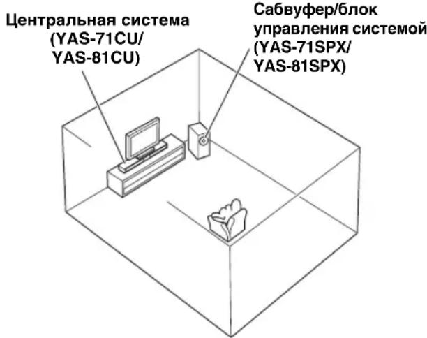
YAS-71/YAS-81 consists of a center system (YAS-71CU/YAS-81CU) and subwoofer/system control (YAS-71SPX/YAS-81SPX). This product provides excellent sound with simple operations, allowing you to enjoy various audio sources. We hope the "YAS-71/YAS-81" brings you great listening pleasure and satisfaction.
■About this manual
- In this manual, operations that can be performed using either the front panel buttons or remote control are explained using the remote control.
- indicates a tip for your operation. Notes contain important information about safety and operating instructions.
- This manual is printed prior to production. Design and specifications are subject to change in part as a result of improvements, etc. In case of differences between the manual and the product, the product has priority.
GETTING STARTED
Supplied parts
This product consists of the following items. Before making connections, make sure you received all of the following items.
■Units
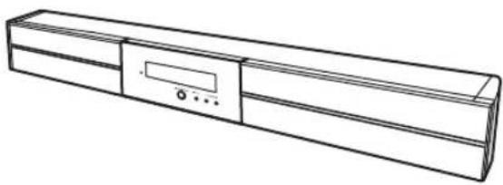
Center system (YAS-71CU/YAS-81CU)
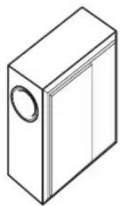
Subwoofer/system control (YAS-71SPX/YAS-81SPX)
■Accessories

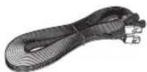
System control cable (4 m)
(4m)
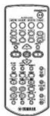
Remote controlSpeakerIudblr FM antenna

Spacer × 2
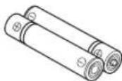
Battery × 2 (AAA, R03, UM4)

Mounting template

Double-sided tape (2 pieces)
Non-skid pad (2 pieces)
Screw × 6
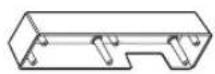

Owner's manual Cover
- All the supplied parts for YAS-81 are included in the box of YAS-81SPX.
Controls and functions
■Front panel of the center system
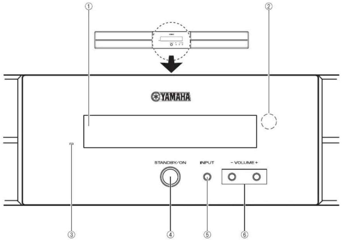
①Front panel display
Shows information about the operational status of the system. (P. 4)
②Remote control sensor
Receives infrared signals from the remote control. (P.5,7)
③Power indicator
Lights up when the system is turned on. (P. 16)
④STANDBY/ON
Turns on the system, or sets it to standby mode. (P. 16)
Note
A small amount of electricity is consumed to receive the infrared signal from the remote control even when the system is in standby mode.
⑤INPUT
Selects an input source you want to listen to. P.16
⑥VOLUME-/+
Controls the volume of the system. (P. 16)
■Front panel display of the center system
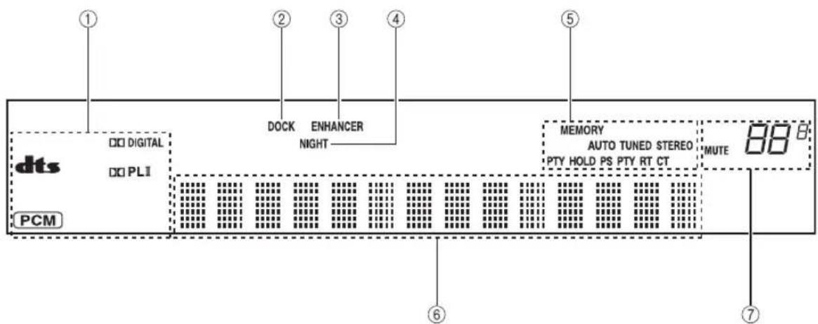
① Decoder indicators
The respective indicator lights up when any of the decoders of the system is functioning.
②DOCK indicator
- Lights up when the system is receiving a signal from an iPod stationed in the Yamaha iPod universal dock (such as YDS-10 or YDS-11, sold separately) connected to the DOCK terminal of the subwoofer/system control. (P. 28)
- Lights up while the Yamaha Bluetooth wireless audio receiver (such as YBA-10, sold separately) is connected to the Bluetooth component. (P. 30)
- Flashes while the connected Yamaha Bluetooth wireless audio receiver (such as YBA-10, sold separately) and the Bluetooth component are pairing or while the Yamaha Bluetooth wireless audio receiver is searching for the Bluetooth component. (P. 30)
③ENHANCER indicator
Lights up when compressed music enhancer mode is selected. (P. 21)
④NIGHT indicator
Lights up when you select night listening mode. (P. 33)
⑤ Tuner indicators (AUTO/TUNED/STEREO/MEMORY)
AUTOindicator
Lights up when the system is in automatic tuning mode. (P. 23)
TUNED indicator
Lights up when the system is receiving a station. (P. 23)
STEREO indicator
Lights up when the system is receiving a strong signal from an FM stereo broadcast in automatic tuning mode. (P. 23)
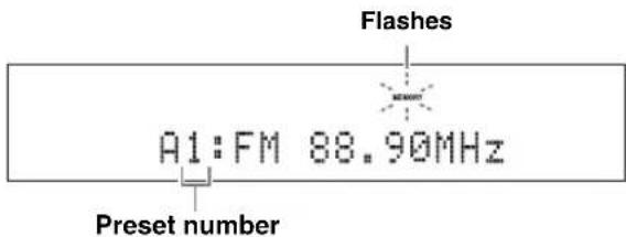
MEMORY indicator
Flashes to show a station can be stored. (P. 24, 25)
PTY HOLD indicator
Lights up while the system is in PTY SEEK mode. (P.27)
PS/PTY/RT/CT indicator
Lights up according to the available Radio Data System information. (P. 26)
^ 6 M u l t i ~ i n f o r m a t i o n ~ d i s p l a y
Shows the selected input source, current surround mode and other information.
MUTE indicator/VOLUME indicator
- Flashes while the mute function is activated. (P. 16)
- Indicates the current volume level.
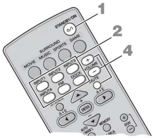
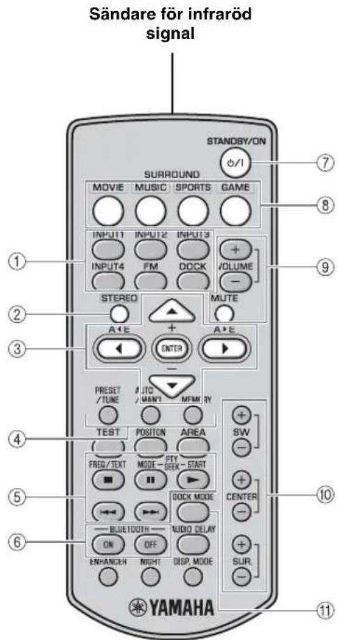
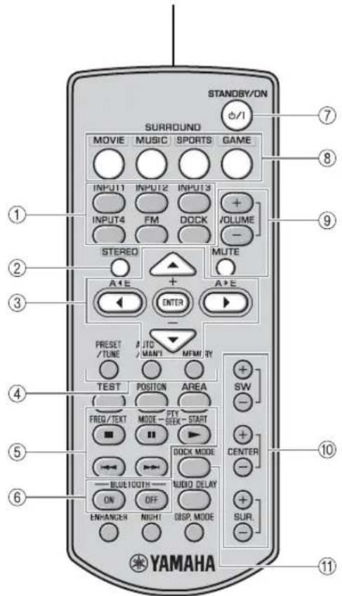
Remote control
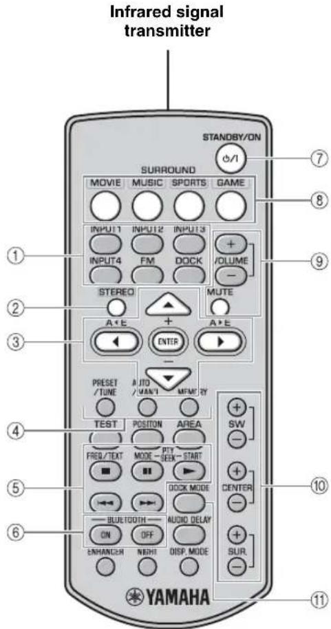
①Input buttons
Select an input source you want to listen to. (P. 16)
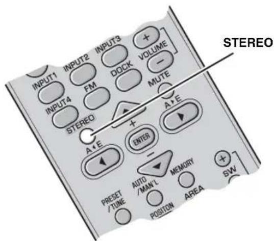
②STEREO
Turns extended stereo mode on and off alternately. (P.21)
Turns off surround mode. (P.18)
③ Cursors (▲/▶/▲/▼)/ENTER
Position: Change the setting. (P. 19)
Audio delay: Change the setting. (P. 32)
iPod: Move the cursor. (P. 28)
FM: Move a preset group and number forward or backward. (P. 22)
4 PRESET/TUNE, AUTO/MAN'L, MEMORY
Control an FM tuner. (P. 22)
⑤ ////11//
Control an iPod or a Bluetooth component. (P. 28, 30)
⑥ BLUETOOTH ON/BLUETOOTH OFF
Connects or disconnects a Bluetooth component. (P.31)
⑦STANDBY/ON
Turns on the system, or sets it to standby mode. (P. 16)
Select surround mode. (P. 18)
⑨VOLUME (+/-)/MUTE
Control the volume of the system. (P. 16)
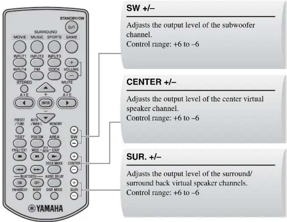
SW (+/-) /CENTER (+/-) /SUR. (+/-)
Adjust the volume balance. (P. 33)
①DOCK MODE
Switches operation mode of the iPod. (P. 28)
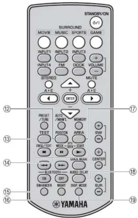
⑫POSITION
Shifts the optimum listening area according to your listening position. (P. 19)
13TEST
Outputs the test tone. (P. 20)
FREQ/TEXT
Switches the information display when receiving Radio Data System. (P.26)
PTY SEEK MODE
Switches the program type. (P. 27)
PTY SEEK START
Starts searching for the program type. (P. 27)
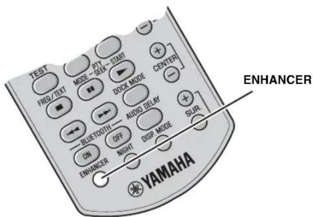
ENHANCER
Turns on and off compressed music enhancer mode alternately. (P. 21)
16NIGHT
Turns night listening mode on or off. (P. 33)
⑦AREA
Selects the optimum listening area. (P. 20)
⑱AUDIO DELAY
Delays the output sound to synchronize it with the video image. (P. 32)
DISP. MODE
Changes the brightness of the front panel display. (P. 34)
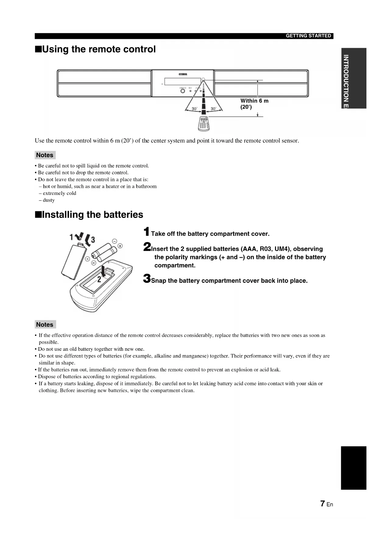
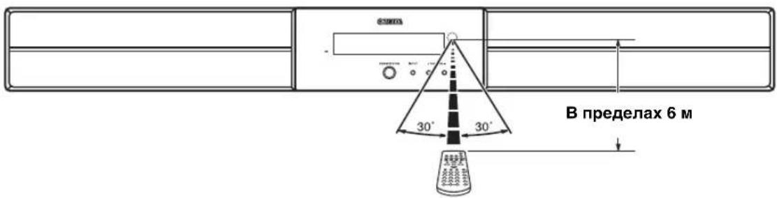
Using the remote control
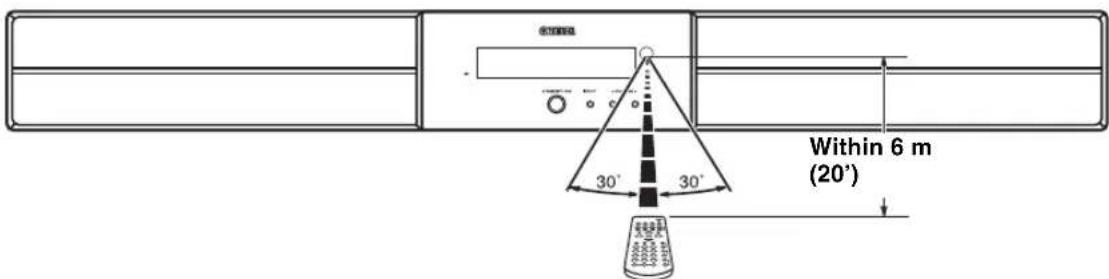
Use the remote control within 6m (20') of the center system and point it toward the remote control sensor.
Notes
- Be careful not to spill liquid on the remote control.
- Be careful not to drop the remote control.
- Do not leave the remote control in a place that is: - hot or humid, such as near a heater or in a bathroom
extremely cold
-dusty
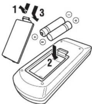
■Installing the batteries
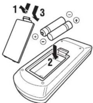
1 Take off the battery compartment cover.
2Insert the 2 supplied batteries (AAA, R03, UM4), observing the polarity markings (+ and -) on the inside of the battery compartment.
3Snap the battery compartment cover back into place.
Notes
- If the effective operation distance of the remote control decreases considerably, replace the batteries with two new ones as soon as possible.
- Do not use an old battery together with new one.
- Do not use different types of batteries (for example, alkaline and manganese) together. Their performance will vary, even if they are similar in shape.
- If the batteries run out, immediately remove them from the remote control to prevent an explosion or acid leak.
- Dispose of batteries according to regional regulations.
If a battery starts leaking, dispose of it immediately. Be careful not to let leaking battery acid come into contact with your skin or clothing. Before inserting new batteries, wipe the compartment clean.
PLACING THIS SYSTEM
To enjoy quality sound thoroughly, you need to place this system in the appropriate positions, and install the components correctly. After deciding the layout, follow the procedure below to install this system.
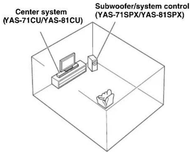
Center system (YAS-71CU/YAS-81CU)
Place the center system beneath a TV or under the TV so that the center system and your TV align vertically. Make sure that the center system is placed in parallel with the wall.
Main roles: Produces front channel (stereo) sounds. Also produces virtual center channel sounds (dialogue, etc.) and virtual surround channel sounds effectively using the Yamaha front surround system.
Subwoofer/system control (YAS-71SPX/YAS-81SPX)
Place the subwoofer near the center system and turn it slightly toward the center of the room to reduce wall reflections. Main roles: Produces low frequency (LFE) sounds.
Notes
This system is shielded against magnetic fields. However, if the picture on your TV screen becomes blurred or distorted, we recommend moving the system away from your TV.
- Low frequency sound produced by the subwoofer/system control may be heard differently depending on the listening position and subwoofer location. To enjoy desired sounds, try changing the location of the subwoofer.
- Depending on your installation environment, connections to external components can be done before installing this system. We recommend that you temporarily place and arrange all components in order to decide which procedure is best done first.
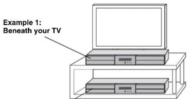
Placing the center system
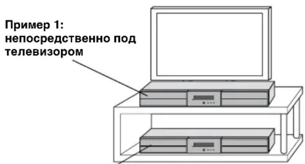
You can place the center system on a rack or attach it to a wall. Select an installation method that suits your environment.
Placing the center system beneath/under a TV
Example 2:Under your TV
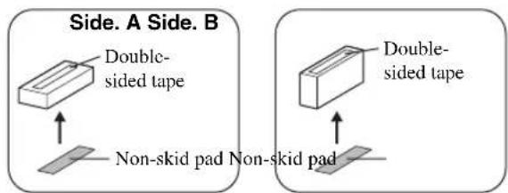
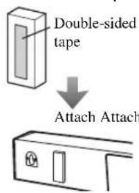
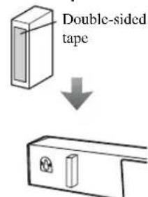
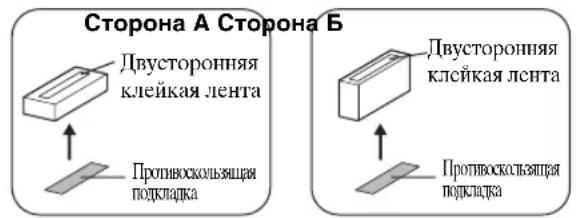
1 Attach the supplied double-sided tapes on the spacers and non-skid pads on the rear of the spacers.
2Attach the spacers to the bottom.
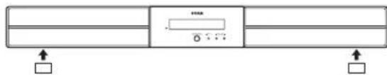

If there is any obstacle (TV stand, etc.) under the center system, use the supplied spacers as follows.
Notes
- Do not cover the remote control sensor of your TV, etc., by the center system.
- The spacers may scratch or damage the surface of your rack or floor. Be careful when placing or moving the center system.
- For your safety, take measures in advance to prevent the center system from falling.
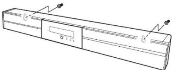
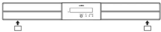
■Attaching the center system to a wall
Installing the center system using the keyholes
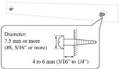
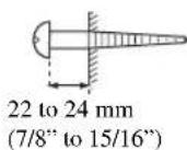
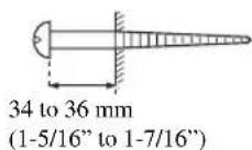
You can attach the center system to a wall using commercially available screws (#8, Diameter: 7.5 mm or more (5/16" or more)).
When installing the center system on a wall, all installation work must be performed by a qualified contractor or dealer. The customer must never attempt to perform this installation work. Improper or inadequate installation could cause the center system to fall, resulting in personal injury.
1 Attach the supplied mounting template on a wall and mark the holes of the mounting template.
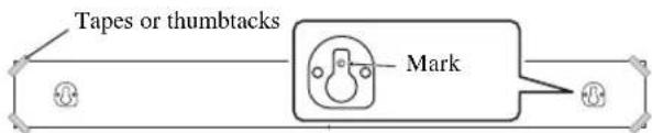
2 Remove the mounting template and then install the commercially available screws at the marks.
To install the cables above the center system, refer to the right column.
3 Hang the center system on the screws using the keyholes on the back of the center system.
Installing the cables above the center system
To pass the cables upward, you need to attach the spacers to make room on the back of the center system.
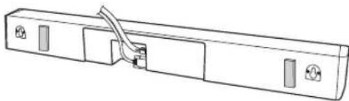
In step 2 of the left column;
2-a: Attach the supplied spacers to the rear panel of the center system using the supplied double-sided tapes. You can choose either the side A or the side B.
A: For narrow space B: For wide space
2-b: Remove the mounting template and then install the commercially available screws at the marks.
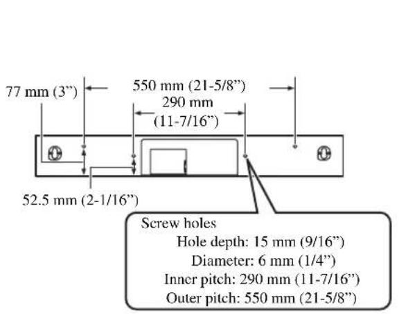
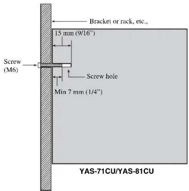
Installing the center system using the screw holes
You can also use the inner or outer screw holes on the rear of the center system for installing the center system using a commercially available bracket or rack.
Notes
- The center system weighs about 5kg (11 lbs.) for YAS-71 and 6kg (13 lbs. 4 oz.) for YAS-81. Attach the center system to a bracket, rack or wall. Do not attach the center system to a wall that is made of weak materials such as plaster or veneered woods. Doing so may cause the center system to fall.
- Use commercially available screws that can support the weight of the installation.
- Make sure you use specified screws to attach the center system. Using clamps other than specified screws, such as short screws, nails, or two-sided tape, may cause the center system to fall.
- When connecting the center system, fix the speaker cables in place where they will not become loose. If your foot or hand accidentally gets caught on a loose speaker cable, the center system may fall.
- After attaching the center system, check that the center system is fixed securely. Yamaha will bear no responsibility for any accidents caused by improper installations.
CONNECTION
- Do not connect the power cable until all connections are completed.
- Do not use excessive force when inserting the cable plug. Doing so may damage the cable plug and/or terminal.
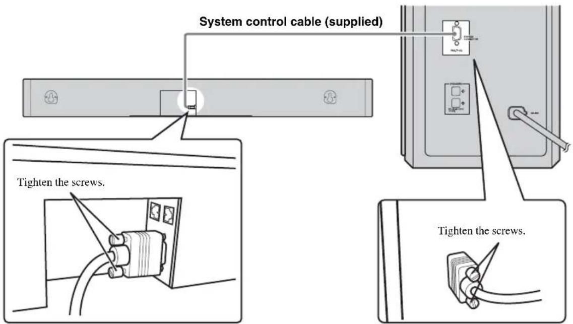
Connecting the center system and the subwoofer/system control
Follow the procedure below to connect the center system and the subwoofer/system control.
Connecting speaker cables
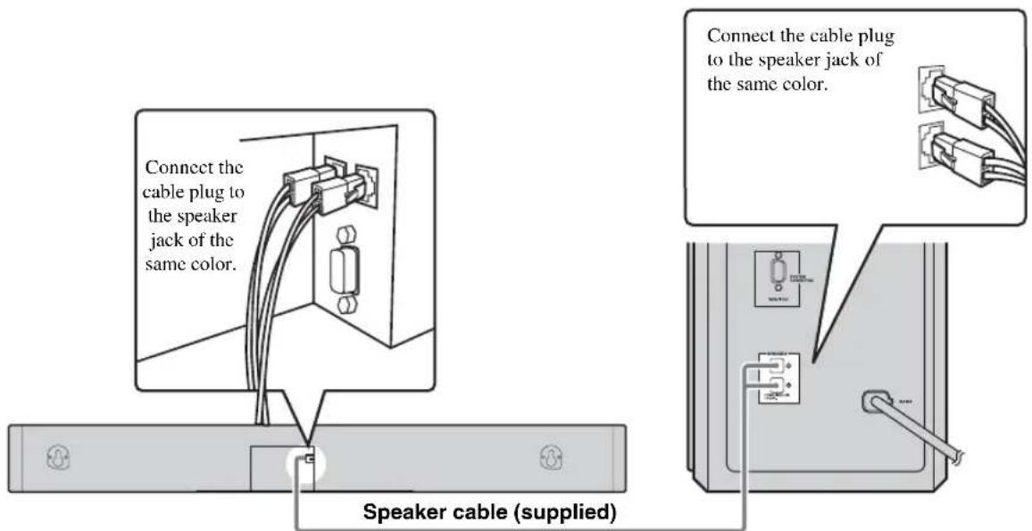
Connecting system control cable
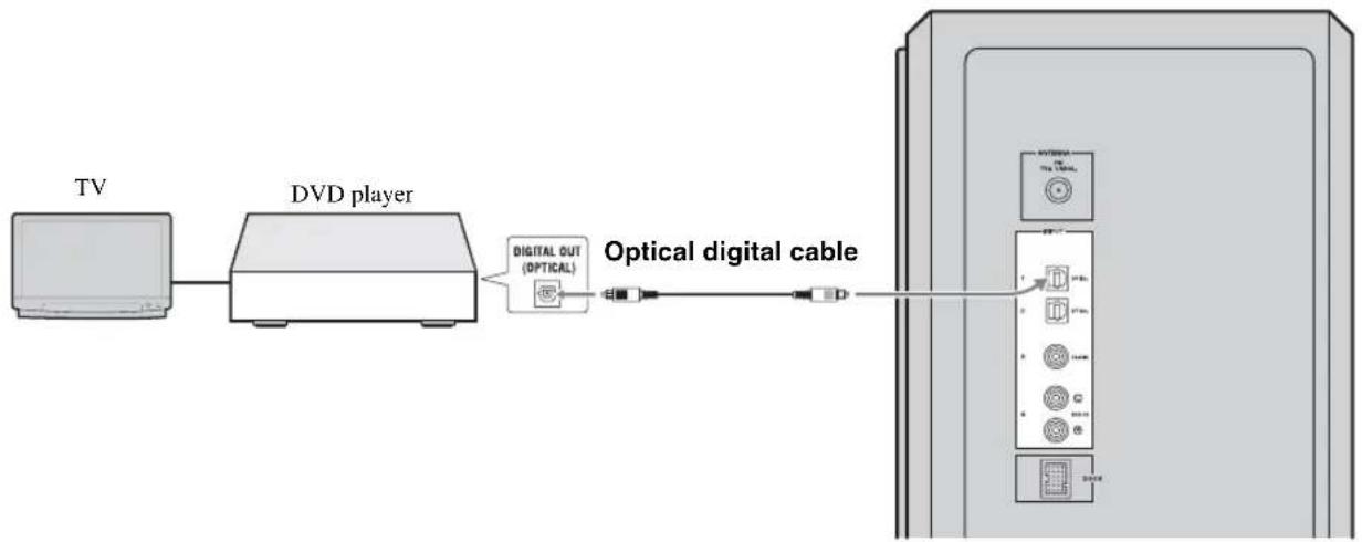
Connecting external components
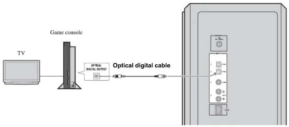
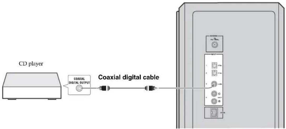
The subwoofer/system control has 3 digital input jacks (optical digital × 2 , coaxial digital × 1 ) and 1 analog input jack. Before connecting your external components, check the output jacks of the components and be sure to use correct connection cables.
Digital connection
Notes
The digital jacks of this system support PCM, Dolby Digital, and DTS bitstream.
The digital jacks support digital signals of 96kHz sampling frequency or less.
[INPUT 1, 2] OPTICAL jack
Example 1: DVD player
Example 2: TV game console
[INPUT 3] COAXIAL jack
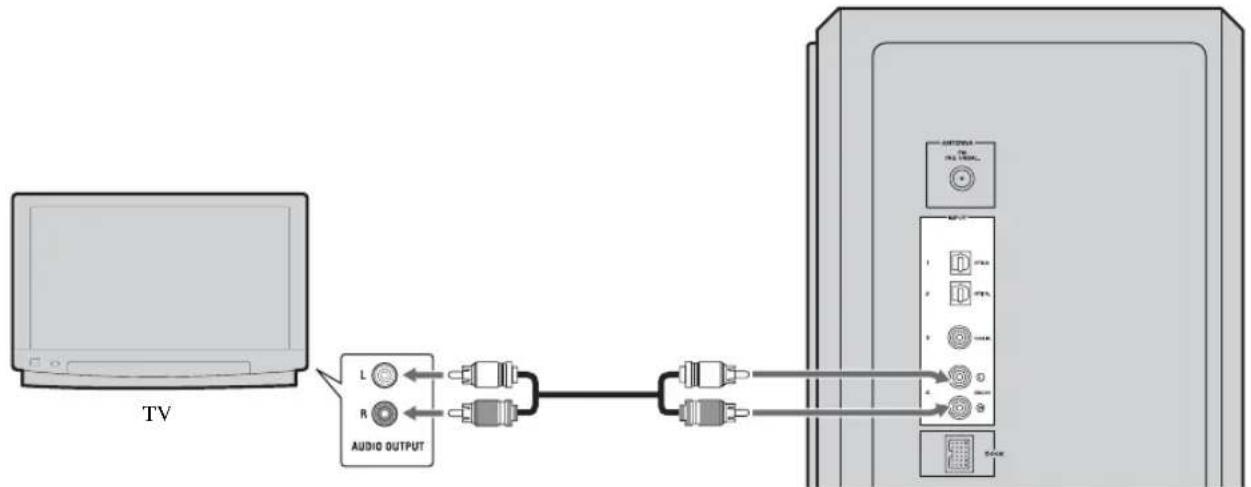
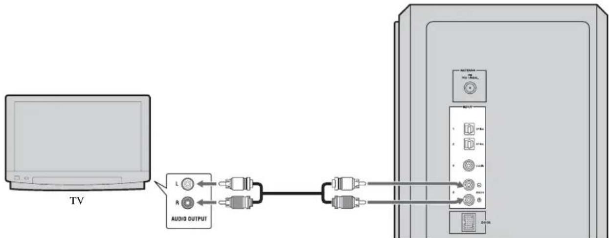
■Analog connection
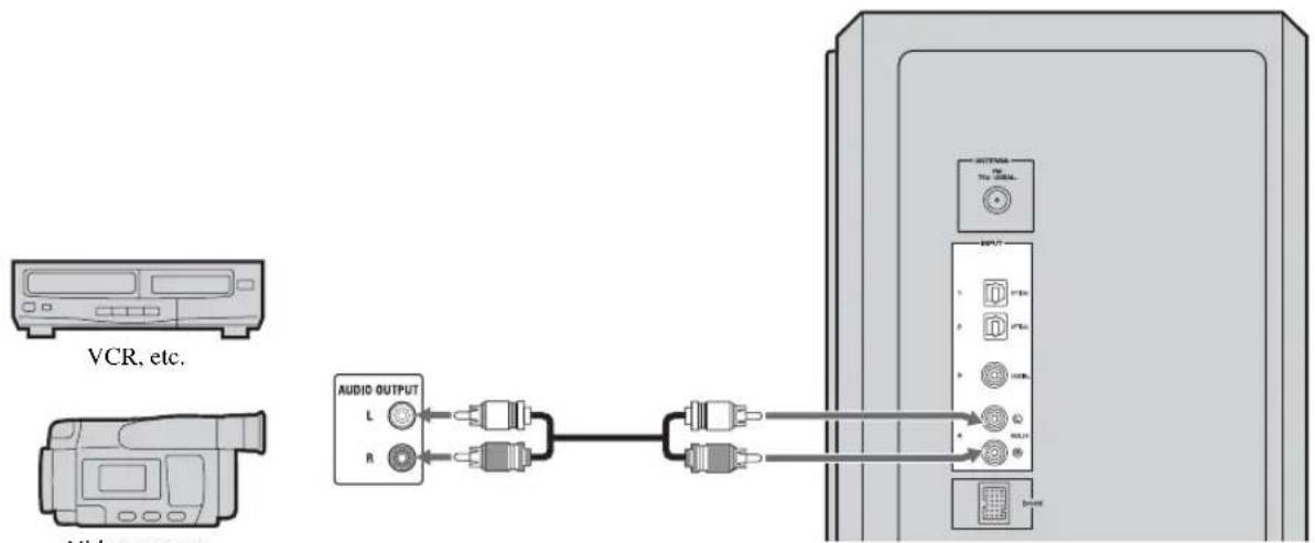
[INPUT 4] ANALOG jacks
Example1: TV
Example 2: VCR or video camera
VCR or video camera, etc., with no digital output.
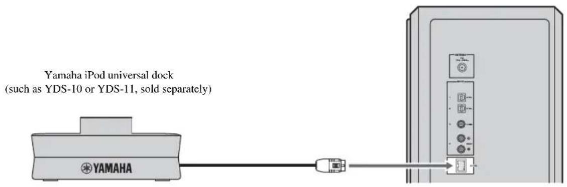
Connecting the Yamaha iPod universal dock
The system is equipped with the DOCK terminal, which allows you to connect the Yamaha iPod universal dock (such as YDS-10 or YDS-11, sold separately) where you can dock your iPod. Connect the Yamaha iPod universal dock to the DOCK terminal of the subwoofer/system control using its dedicated cable. Refer to "Using iPodTM" on page 28 for details.
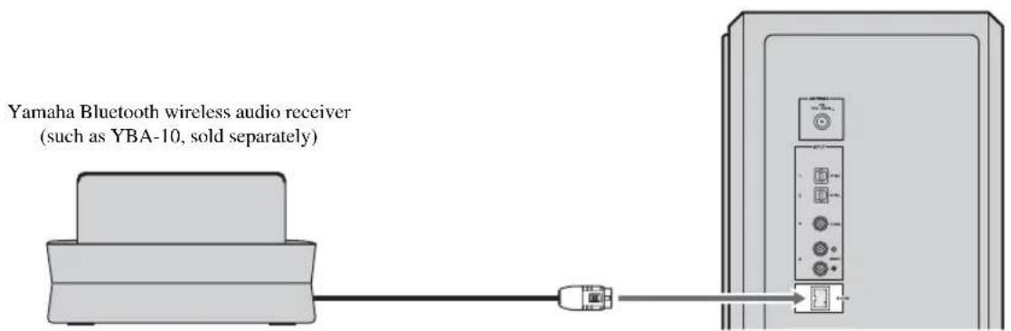
Connecting the Yamaha Bluetooth wireless audio receiver
You can also connect the Yamaha Bluetooth wireless audio receiver (such as YBA-10, sold separately) to the DOCK terminal. Connect the Yamaha Bluetooth wireless audio receiver to the DOCK terminal of the subwoofer/system control using its dedicated cable. Refer to "Using Bluetooth™ Components" on page 30 for details.
Connecting the indoor FM antenna
To enjoy FM radio broadcasts, connect the supplied indoor FM antenna.
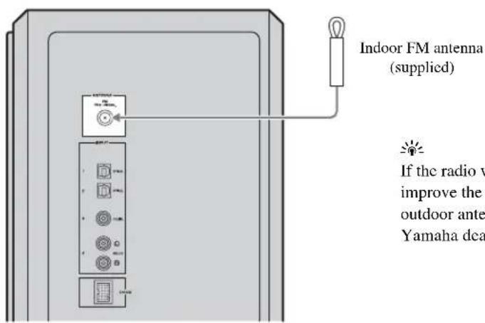
If the radio wave reception is weak in your area or you want to improve the radio wave reception, we recommend that you use an outdoor antenna. For details, consult your nearest authorized Yamaha dealer or Service Center.
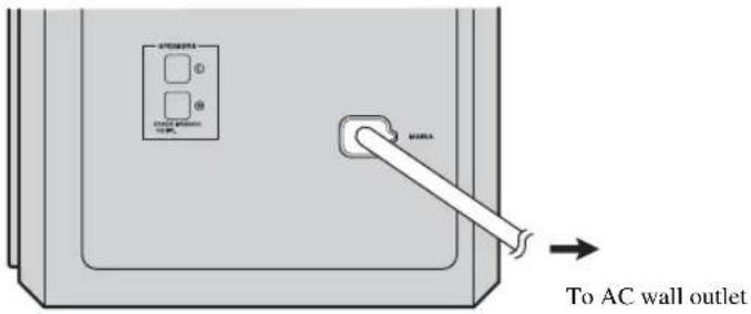
Connecting the power cable
After you have made all connections, connect the power cable of the subwoofer/system control.
中
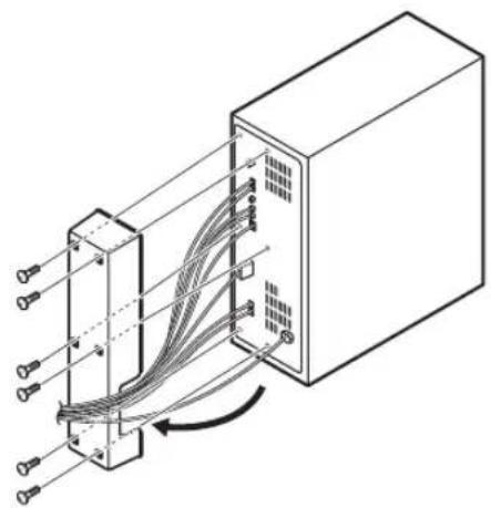
You can attach the cover after you have made all connections or detach according to your preference. Attach the cover to the rear panel of the subwoofer/system control using the 6 supplied screws as shown.
Once you have finished all cable connections (P. 11 to 15) and remote control preparation (P. 7), follow the procedure below to start basic playback operation.
1 Press STANDBY/ON.
This system is turned on and the power indicator lights up. To set the system to standby mode, press STANDBY/ON again.
中
This system has the auto-sleep function, which will automatically switch the system to standby mode if the system is left turned on for 24 hours without any operation being performed.
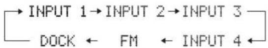
2Press one of the input buttons to select an input source.
For example, if a DVD player is connected to the INPUT 1 jack of the subwoofer/system control, press INPUT 1 to select the DVD player.
中
You can also switch the input source by pressing INPUT on the center system repeatedly. The input source changes as follows:
3Start playback on the selected external component.
For information on the external component, refer to the manual for the product.
4 Press VOLUME + / - to adjust the volume level.

To turn off the volume temporarily, press MUTE. While the mute function is activated, the MUTE indicator flashes. To resume the volume, press MUTE again.
Now, try various features of this system!
Using various sound features
To enjoy highly realistic sounds with surround mode P.18
To shift the optimum listening area from side to side P.19
To select the optimum listening area P.20
To experience wider stereo sound when surround mode is not activated P.21
To play back compressed audio signals with high-quality sound P.21
To delay the sound output in order to synchronize it with the video image P.32
To enjoy various input sources at lower volume P.33
Enjoying FM broadcasts/ optional equipment
To listen to FM broadcasts P.22
To control iPod playback P.28
To play back a Bluetooth component P.30
AIR SURROUND XTREME
What is AIR SURROUND XTREME?
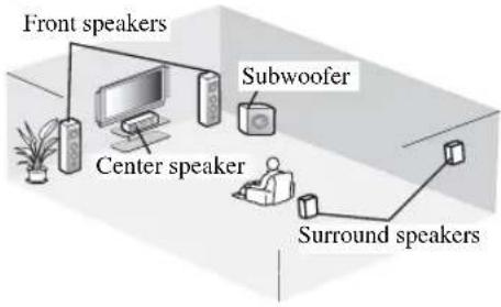
Ordinarily, two front speakers, a center speaker, two surround speakers, and a subwoofer are necessary for enjoying 5.1 channel surround sound.
■Virtual 7.1 channel
The AIR SURROUND XTREME technology, using only the front left and right speakers of the center system and subwoofer, enables you to enjoy a realistic 7.1 channel sound by simulating sound from virtual speakers at center, surround, and surround backs.
Typical 5.1 channel speaker system
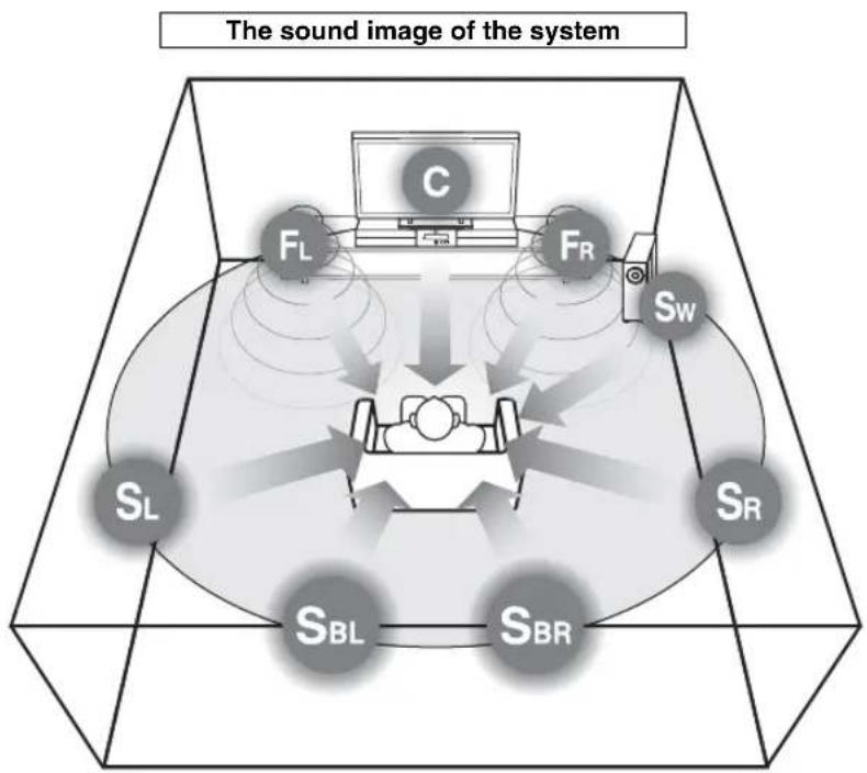
The system creates the virtual 7.1 channel surround sound with the center system and the subwoofer/ system control.
C: Center virtual speaker
FR, FL: Front speakers
SW: Subwoofer
SR, SL: Surround virtual speakers
SBR, SBL: Surround back virtual speakers
You can check the virtual surround effect and adjust the volume balance according to your preference and the characteristics of your listening room. See the following pages for details.
- Checking the virtual surround effect P. 20
Adjusting the volume balance P. 33
Use this feature to adjust the volume balance of the subwoofer, center, and surround channels during playback.
Listening to surround mode of AIR SURROUND XTREME
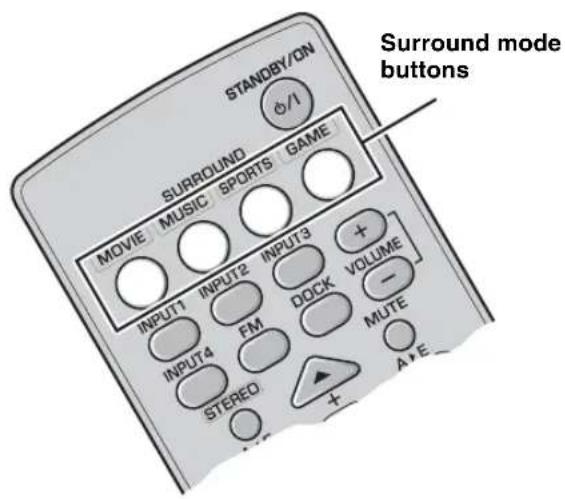
Press one of the surround mode buttons.
The names of the selected input source and the selected surround mode appear in the front panel display.
INPUT1 :MOVIE
Surround mode descriptions
Movie

This mode is useful when you enjoy movie contents on media such as DVD, etc.
Music

This mode is useful when you listen to music contents on media such as DVD, etc.
Sports

This mode is useful when you enjoy sports programs or TV news.
Game

This mode is useful when you enjoy video games.

To reproduce the original sounds, press STEREO.
- The system automatically memorizes the settings assigned to each input source. When you select another input, the system automatically recalls the last settings for the selected input.
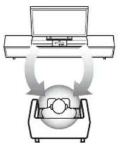
Shifting the optimum listening area from side to side
This function shifts the optimum listening area from side to side according to your listening position for the best Virtual Surround effect.
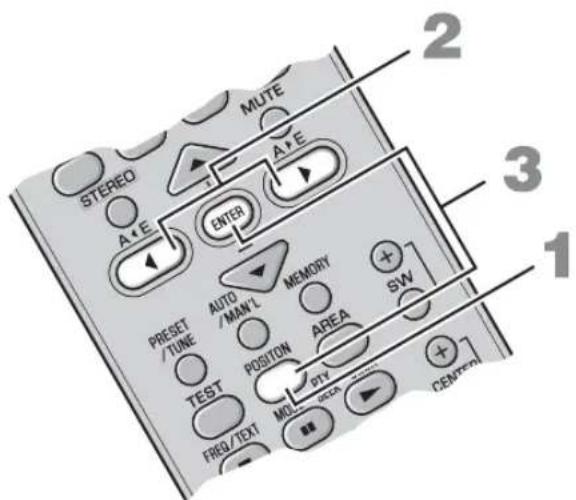
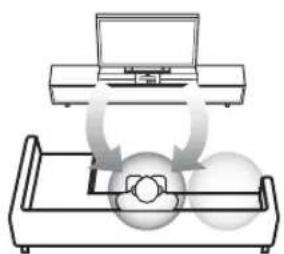
The optimum listening area
1 Press POSITION to enter position mode. The current position appears in the front panel display.
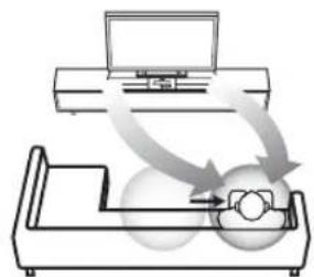
2 Press /> to shift the optimum listening area (L6, L5, L4, L3, L2, L1, CENTER, R1, R2, R3, R4, R5, R6).
Adjust the optimum listening area from L1 to L6 when your listening position is to the left side of the center system, and adjust the optimum listening area from R1 to R6 when your listening position is to the right side of the center system.
The position appears in the front panel display.
POSITION L1
Example: "POSITION L1"
3 Press POSITION again or ENTER to exit position mode.
中
- The default setting is CENTER.
- If you press TEST after performing step 1, the system outputs the test tone for a virtual center speaker so you can adjust the position setting. (P.20)
- The setting is set for all the input sources.
- This function is available even when surround mode is off.
Note
If you do not operate this function within 30 seconds after entering position mode, the system automatically exits position mode.
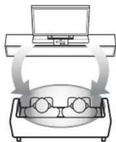
Selecting the optimum listening area
You can select the optimum listening area from two modes.
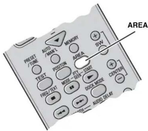
NORMAL WIDE
Press AREA.
Each time you press AREA, NORMAL and WIDE modes change alternately.
NORMAL
Select this to sharpen the sound effect.
"AREA NORMAL" appears in the front panel display when NORMAL mode is selected.
AREA NORMAL
WIDE
Select this to widen the optimal listening area.

- The default setting is NORMAL.
- The setting is set for all the input sources.
Note
This operation is only available when surround mode is activated.
Checking the virtual surround effect
You can check the Virtual Surround effect using test tones produced from the speakers.
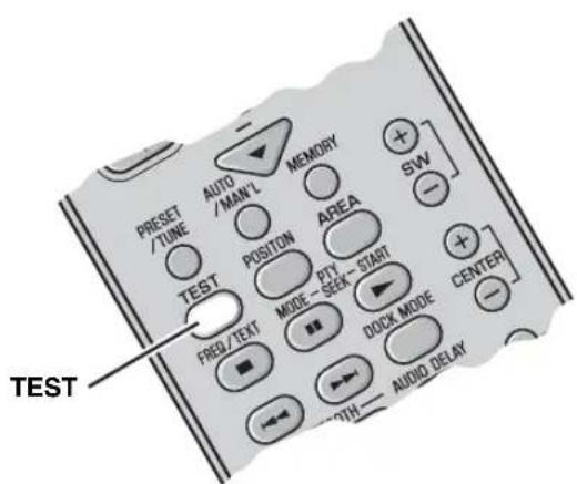
Press TEST to output the test tone.
The system outputs the test tone and the output channel of the test tone appears in the front panel display.

The output channel of the test tone cycles through as follows. Each channel outputs the test tone for about 2 seconds.
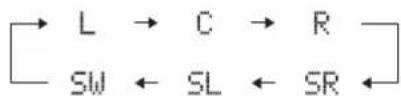

To cancel test tone mode, press TEST again.
Note
The surround back virtual speaker is included in SL and SR.
Using extended stereo mode
An extended sound is achieved for a 2 channel source such as a CD player.
Press STEREO to enter extended stereo mode.
"EXTENDED" appears in the front panel display.
EXTENDED
Each time you press STEREO, the function is turned on (EXTENDED) and off (STEREO) alternately.
#
The default setting is STEREO.
- The system memorizes the settings assigned to each input source.
- You can also turn on compressed music enhancer mode when extended stereo mode is turned on.
Note
This operation is only available when surround mode is not activated.
Setting compressed music enhancer
This function enhances your listening experience by regenerating the missing harmonics in a compression artifact.
This is useful when you play back compressed music data stored on an iPod or a digital music player.
Press ENHANCER.
The ENHANCER indicator lights up in the front panel display when this function is turned on.
Each time you press ENHANCER, the function is turned on and off alternately. The selected mode is stored in memory even when the power is off.
中
The default setting is OFF.
- The system memorizes the settings assigned to each input source.
- When this function is on, night listening mode is automatically set to off. (P. 33)
LISTENING TO FM BROADCASTS
Overview
You can use two tuning modes to tune into the desired FM station:
Frequency tuning mode
You can search or specify the frequency of the desired FM station automatically or manually. (See "Basic tuning operation" on page 23.)
Preset tuning mode
You can preset the desired FM station in advance, and then recall the station by specifying the preset group and number. (See "Using station preset feature" on page 24.)
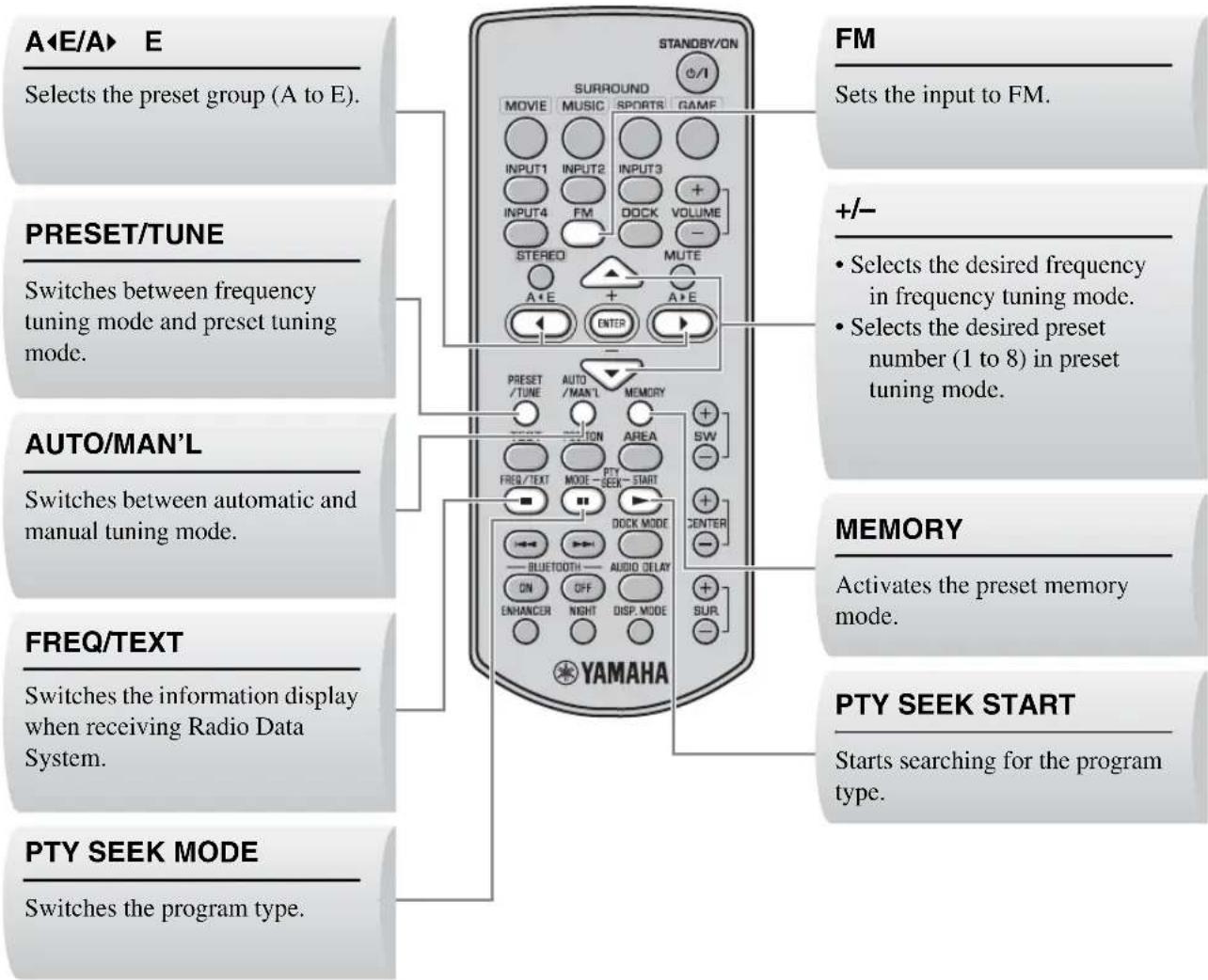
Controls and functions for the FM tuning
Basic tuning operation
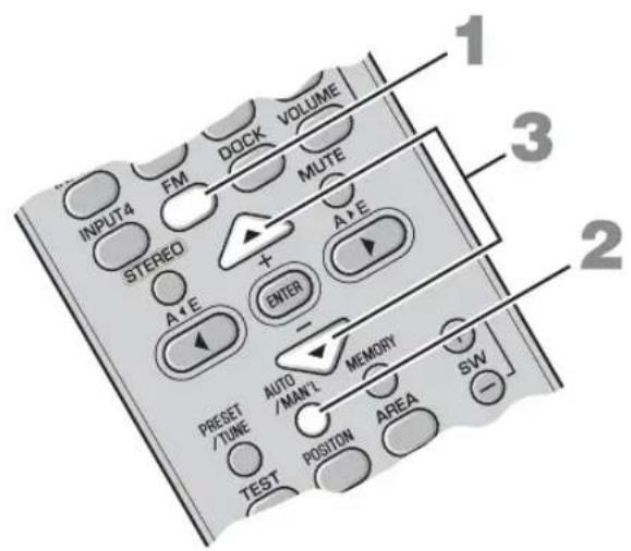
Manual tuning
If the signal received from the station you want to select is weak, you can tune into the desired station by specifying the frequency manually. In FM tuning mode, press AUTO/MAN'L repeatedly so that the AUTO indicator disappears, and then press +/- repeatedly to specify the frequency of the desired station.
If you tune to a station using the manual tuning feature, the system receives the FM radio signals in monaural reception mode to increase signal quality.
1 Press FM to set the input to FM.
"FM" appears in the front panel display.
F M
2 Press AUTO/MAN'L to switch Auto/Manual.
The AUTO indicator lights up when the system is set to automatic tuning mode.
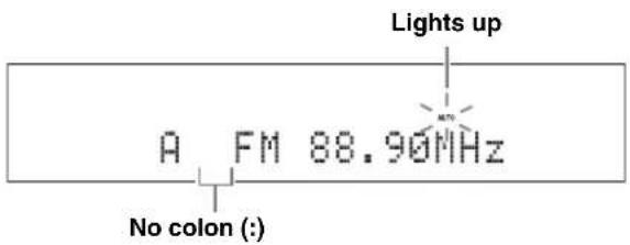

If a colon (·) appears, the system is set to preset tuning mode. (P. 24)
3 Press +/- once to begin automatic tuning.
When the system is tuned to a station, the TUNED indicator lights up and the frequency of the received station is shown in the front panel display.
Lights up
FM89.10MHZ

When you tune to an FM station using automatic tuning mode, the system receives the FM radio signal in stereo reception mode. The STEREO indicator appears in the front panel display.
Using station preset feature
Automatic station preset
You can store up to 40 FM stations (A1 to E8: 8 preset numbers in each of the 5 preset groups).
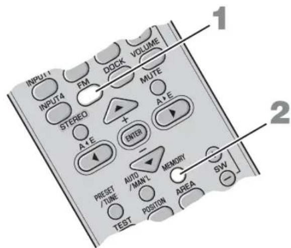
1 Press FM to set the input to FM.
"FM" appears in the front panel display.
2 Press and hold MEMORY for more than 3 seconds.
The preset group and number as well as the MEMORY and AUTO indicators flash. After approximately 5 seconds, automatic presetting starts from the current frequency and proceeds through higher frequencies.
Press MEMORY again to cancel while the MEMORY indicator is flashing.
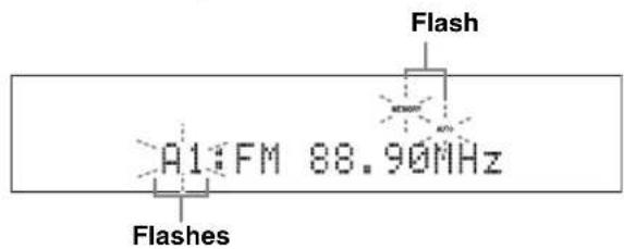
When automatic preset tuning is completed, the front panel display shows the frequency of the last preset station.

Press A E or A E to select a preset group, and then press + / - repeatedly to select a preset number to which the first station will be stored after you perform step 2.
Notes
- Any stored station data existing under a preset number is cleared when you store a new station under the same preset number.
If the number of received stations does not reach 40 (A1 to E8), automatic preset tuning automatically stops after searching for all the available stations.
If the desired station is not stored, or a station is not stored to the desired preset group and number, preset the station manually. Refer to "Manual station preset" on page 25 for details.
Manual station preset
Use this feature to preset your desired station manually.
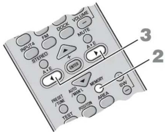
1 Tune into a station.
See "Basic tuning operation" on page 23 for tuning instructions.
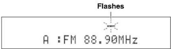
2Press MEMORY.
The MEMORY indicator flashes in the front panel display for approximately 30 seconds.
Press MEMORY again to cancel while the MEMORY indicator is flashing.
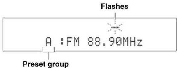
3 Press A< E or A> E repeatedly to select a preset group (A to E) while the MEMORY indicator is flashing.
The selected preset group appears.
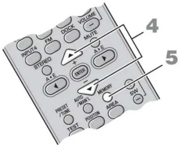
4 Press +/- to select a preset number (1 to 8) while the MEMORY indicator is flashing.
5 Press MEMORY to confirm the preset.
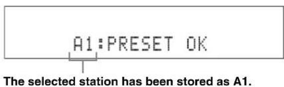
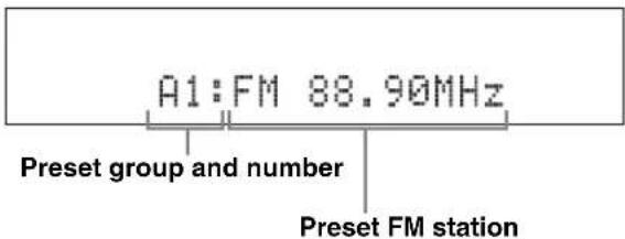
After "A1:PRESET OK" appears in the front panel display, the frequency appears with the preset group you selected. The MEMORY indicator disappears from the front panel display.
A FM 88.90MHz
Notes
- Any stored station data existing under a presct number is cleared when you store a new station under the same presct number.
- Reception mode (stereo or monaural) is stored along with the station frequency.
Recalling the preset stations
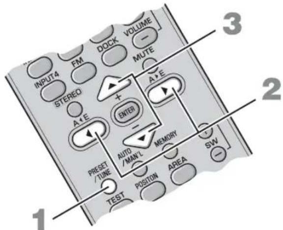
1 Press PRESET/TUNE to select preset tuning mode.
2 Press A E or A E repeatedly to select the desired preset group (A to E).
3 Press +/- repeatedly to select the desired preset number (1 to 8).
Receiving Radio Data System stations
The Radio Data System is a data transmission system used by FM stations in many countries. The system can receive various Radio Data System data such as PS (program service), PTY (program type), RT (radio text) and CT (clock time) when receiving Radio Data System broadcasting stations.
To switch the information display of Radio Data System
While receiving Radio Data System, press FREQ/TEXT. Each time you press the button, the information display changes as follows:

Information type
- PROGRAM SERVICE (PS)
Displays the currently received Radio Data System program.
- PROGRAM TYPE (PTY)
Displays the type of the currently received Radio Data System program.
- RADIO TEXT (RT)
Displays the information of the currently received Radio Data System program.
CLOCK TIME (CT)
Displays the current time.
FREQUENCY
Displays the frequency and preset group and number.
Notes
- You can select one of the Radio Data System display modes only when the corresponding Radio Data System indicator lights up in the front panel display. It may take a while for the system to receive all of the Radio Data System data from the station.
- You can select only the available Radio Data System display modes being offered by the station.
- If the signals being received are not strong enough, the system may not be able to utilize the Radio Data System data. In particular, RT mode requires a large amount of data and may not be available even when other Radio Data System display modes are available.
- In case of poor reception conditions, press AUTO/MAN'L to select Manual tuning. (P. 23)
- If the signal strength is weakened by external interference while the system is receiving the Radio Data System data, the reception may be cut off unexpectedly and "...WAIT" appears in the front panel display.
- When RT mode is selected, the system can display the program information with a maximum of 64 alphanumeric characters, including the umlaut symbol. Unavailable characters are displayed with underscores “_”.
- If the reception is cut off when CT mode is selected, "CT WAIT" appears in the front panel display.
To select stations by program type (genre)
You can tune Radio Data System stations by selecting a program type (genre) from 15 options. Once you select a program type, the system automatically searches for a program type from the all preset Radio Data System broadcasting stations.
1 Press PTY SEEK MODE to set the system to PTY SEEK mode.
The name of the program type or "NEWS" flashes in the front panel display.
Flashes

中
To cancel PTY SEEK mode, press PTY SEEK MODE again.
2 Press + / - to select the program type.
The name of the selected program type appears in the front panel display.
Program type Descriptions
| NEWS News |
| AFFAIRS Current affairs |
| INFO General information |
| SPORT Sports |
| EDUCATE Education |
| DRAMA Drama |
| CULTURE Cultures |
| SCIENCE Science |
| Program type | Descriptions |
| VARIED Light entertainment | |
| POP M Popular music | |
| ROCK M Rock music | |
| M.O.R.M Middle-of-the-road music(easy-listening) | |
| LIGHT M Light classics | |
| CLASSICS | Serious classics |
| OTHER M | Other music |
3 Press PTY SEEK START to start searching for all the available Radio Data System preset stations.
The name of the selected program type flashes and the PTY HOLD indicator lights up in the front panel display.

中
To stop searching for stations, press PTY SEEK START again.
Notes
- The system stops searching for stations when a station broadcasting the selected program type is found.
- If the station found is not the one you desire, press PTY SEEK START again to resume searching for another station broadcasting the same program type.
USING OPTIONAL EQUIPMENT
Using iPodTM
Once you have stationed your iPod in the Yamaha iPod universal dock (such as YDS-10/ YDS-11, sold separately) connected to the DOCK terminal of the subwoofer/system control (P. 14), you can enjoy playback of your iPod.
Supported iPod
iPod (Click and Wheel)
iPod nano
iPod mini
iPod touch
Battery charge feature
This system charges the battery of an iPod stationed in the Yamaha iPod universal dock connected to the DOCK terminal of the subwoofer/system control while this system is turned on.
Stationing your iPod in the Yamaha iPod universal dock
Once you station your iPod in the Yamaha iPod universal dock, "iPod connected" and the DOCK indicator appear in the front panel display.
Notes
- Some features may not be available depending on the model or the software version of your iPod.
For a complete list of status messages that appear in the front panel display, see the "iPod" section in "Troubleshooting" on page 36. - Be sure to set the volume to minimum before docking or removing your iPod.
Controls and functions for iPodTM
You can control your iPod in simple remote mode or menu browse mode.

You can switch between simple remote mode and menu browse mode by pressing DOCK MODE.
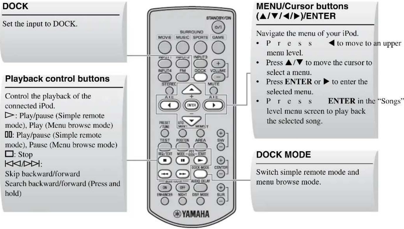
■Controlling your iPod in simple remote mode
Docking your iPod in the Yamaha iPod universal dock (such as YDS-10 or YDS-11, sold separately) enters simple remote mode. You can perform the basic operations of your iPod (play, stop, skip backward/forward, etc.) using the supplied remote control in this mode.
中
Operations can be also done with the controls on your iPod. Refer to the instruction manuals of your iPod for its operations.
■Controlling your iPod in menu browse mode
The song lists or playback information is displayed in the front panel display so that you can select and play back songs or adjust settings using the supplied remote control in this mode.
Notes
- Operations cannot be done with the controls of your iPod.
- Characters that cannot be displayed in the front panel display are replaced with underscores “_”.
1 Press DOCK MODE to enter menu browse mode.
2 Press / / repeatedly to select the desired menu, and then press ENTER to play back the selected song.
Options Level 1 Level 2 Level 3 Level 4
| Playlists Playlist Song list | |
| Artists Artist list Album list Song list | |
| Albums Album list Song list | |
| Songs Song list | |
| Genres Genre list Artist list Album list Song list | |
| ComposersComposer list Album list Song list | |
| Settings Setting list |
The setting list has the following 2 choices.
Shuffle
Use this feature to set the system to play songs or albums in random order.
Options: Off, Songs, Album
You can switch each option by pressing ENTER.
- Select "Off" to deactivate this feature.
- Select "Songs" to set the system to play songs in random order.
- Select "Album" to set the system to play albums in random order.
Repeat
Use this feature to set the system to repeat one song or a sequence of songs.
Options: Off, One, All
You can switch each option by pressing ENTER.
- Select "Off" to deactivate this feature.
- Select "One" to set the system to repeat one song.
- Select "All" to set the system to repeat a sequence of songs.
Note
The contents of the iPod menu vary, depending on the model or the generation.
Using Bluetooth™ components
You can connect the Yamaha Bluetooth wireless audio receiver (such as YBA-10, sold separately) to the DOCK terminal of the subwoofer/system control and enjoy the music contents stored in your Bluetooth component (such as a portable music player or computer equipped with a Bluetooth transmitter, etc.) without wiring between the system and the Bluetooth component. You need to perform "pairing" of the connected Yamaha Bluetooth wireless audio receiver and your Bluetooth component in advance.
Controls and functions for Bluetooth components
DOCK
Set the input to DOCK.
BLUETOOTH ON/OFF
- Start or cancel the pairing.
- Connect or disconnect a Bluetooth component.
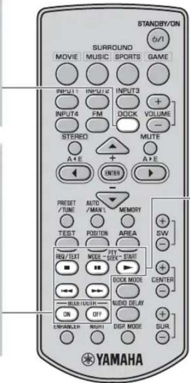
Playback control buttons
Control the playback of a Bluetooth component.
:Play
: Pause
□:Stop
KAA
Skip backward/forward
■Pairing the Yamaha Bluetooth™ wireless audio receiver and your Bluetooth™ component
Pairing must be performed before using a Bluetooth component with the Yamaha Bluetooth wireless audio receiver connected to the system for the first time or if the registered pairing data has been deleted. "Pairing" refers to the operation of registering a Bluetooth component for Bluetooth communications.
To ensure security, a time limit of 8 minutes is set for the pairing operation. Please read and fully understand all the instructions before starting.
1 Connect the Yamaha Bluetooth wireless audio receiver to the DOCK terminal of the subwoofer/ system control. (rP. 14)
2 Press DOCK to set the input to DOCK.
3 Turn on the Bluetooth component you want to pair with, and then enter pairing mode. Refer to the instruction manual of your Bluetooth component for details.
4 Press and hold BLUETOOTH ON for more than 3 seconds to start pairing.
"Searching..." appears when the pairing starts. While the Yamaha Bluetooth wireless audio receiver is in pairing mode, the DOCK indicator flashes in the front panel display.
To cancel the pairing, press BLUETOOTH OFF.
5 Check that the Bluetooth component detects the Yamaha Bluetooth wireless audio receiver.
If the Bluetooth component detects the Yamaha Bluetooth wireless audio receiver, the audio receiver name ("YBA-10 YAMAHA" for example) appears in the device list of the Bluetooth component.
6 Select the Yamaha Bluetooth wireless audio receiver in the device list of the Bluetooth component, and then enter the pass key "0000" on the Bluetooth component.
When the pairing procedure is successful, "Completed" appears in the front panel display.
- If the pairing is not completed within 8 minutes, "Not found" appears and the DOCK indicator is turned off in the front panel display.
- If the pairing is canceled during the pairing, "Canceled" appears in the front panel display.
Note
The Yamaha Bluetooth wireless audio receiver can be paired with up to eight Bluetooth components. When pairing is conducted successfully with a ninth component and the pairing data is registered, the pairing data for the least recently used another component is deleted.
■Establishing a connection
After the pairing is completed, perform the connecting operation on the system or on the Bluetooth component to enable communication between them. The connecting operation on the system is only available for the most recently connected Bluetooth component.
1 Press DOCK to set the input to DOCK.
2 Press BLUETOOTH ON to start a connection. "Searching..." appears in the front panel display. When the system finds the last connected Bluetooth component, "BT connected" appears in the front panel display for 3 seconds.
中
- If the system cannot find the last connected Bluetooth component, "Not found" appears in the front panel display.
- If you want to establish a connection with a Bluetooth component other than the one most recently connected to, connect from that Bluetooth component. Refer to the instruction manual of your Bluetooth component for details.
■Disconnecting
Press DOCK, and then BLUETOOTH OFF to disconnect the system from the Bluetooth component.
"Disconnected" appears in the front panel display.
■Playing back the Bluetooth component
You can play back your Bluetooth component using the supplied remote control.
You can also play back your Bluetooth component by operating it directly.
中
Operation using the remote control is available only when the connection is established between the Bluetooth component you want to play back and the system.
FPD TV images sometimes lag behind the sound. You can use this function to delay the sound output to synchronize it with the video image.
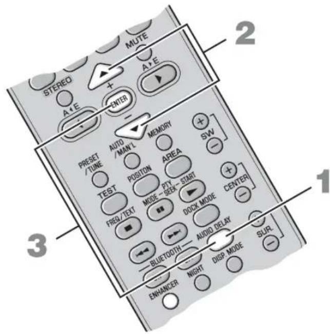
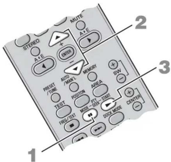
1 Press AUDIO DELAY to enter adjusting mode.
2 Press / to adjust the delay time.
Options: 0 to 240ms
You can adjust the delay time by the 10ms
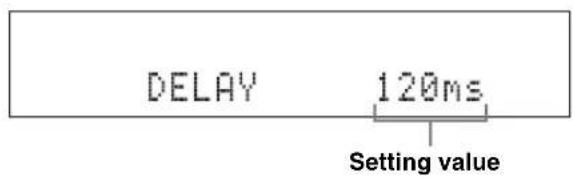
3 Press AUDIO DELAY again or ENTER to exit adjusting mode.
中
- The default setting is 0ms and "DELAY OFF" appears in the front panel display.
- The system memorizes the settings assigned to each input source.
Note
If you do not operate this function within 30 seconds after entering adjusting mode, the system automatically exits adjusting mode.
LISTENING AT LOW VOLUME (NIGHT LISTENING MODE)
Night listening mode enables you to listen to dialog or vocals more clearly at lower volume by suppressing louder sound effects. This function is useful when you enjoy movies or music at night.
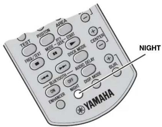
Press NIGHT.
"Night ON" appears in the front panel display. The NIGHT indicator lights up when Night listening mode is selected.


- To cancel night listening mode, press NIGHT again.
- When this function is on, compressed music enhancer mode is automatically set to off. (P. 21)
- The setting is set for all the input sources.
ADJUSTING THE VOLUME BALANCE DURING PLAYBACK
You can adjust the volume balance of the virtual speakers and subwoofer.
- You can also adjust the speaker volume while the test tone is output. (P. 20)
- The setting is set for all the input sources.
CHANGING THE BRIGHTNESS OF THE FRONT PANEL DISPLAY
You can change the brightness of the front panel display. You can also turn off the front panel display to view a movie in a darker environment.
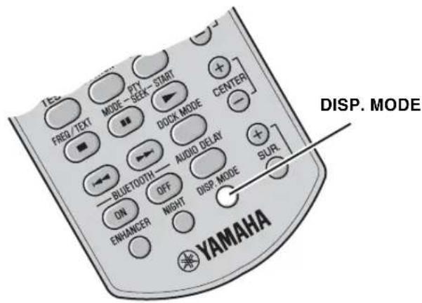
Press DISP. MODE repeatedly.
Each time you press DISP. MODE, the brightness of the front panel changes.
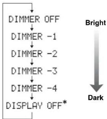
- Selecting DISPLAY OFF turns off the front panel display after "DISPLAY OFF" appears in the front panel display.
The front panel display lights up momentarily when any operation is performed with DISPLAY OFF mode selected.
Only the power indicator remains lit in DISPLAY OFF mode.

The default setting is DIMMER OFF.
ADDITIONAL INFORMATION
Troubleshooting
If there is any problem with the system, check the following items. If you cannot solve a problem with the following remedies, or if the problem is not listed below, turn off and unplug the system, and then consult your nearest authorized Yamaha dealer or Service Center.
| Problem Cause Solution | See page | ||
| Power turns on but immediately shuts off. | The power cable may be connected improperly. | Make sure the power cable is plugged into the outlet firmly. | 15 |
| A speaker cable may be shorted. Make sure all speaker cables are connected properly. | 11 | ||
| This system may have received a strong electrical shock, such as from a lightening bolt or excessive static electricity. | Set this system to standby mode, and then disconnect the power cable. Wait for about 30 seconds, connect the power cable, and then turn the system on again. | 16 | |
| The speakers make no sound. | The volume may be set to minimum level. | Adjust the volume level. | 16, 33 |
| The mute function may be activated. Cancel the mute function. 16 | |||
| The input source or input setting may be incorrect. | Select the correct input source or input setting. | 16 | |
| The cables may be connected improperly. | Make sure all cables are connected properly. | 11 | |
| Sound is too low on one side. | The cables may be connected improperly. | Make sure all cables are connected properly. | 11 |
| Speaker channels other than the front ones make no sound. | You may be listening to stereo sounds without surround mode. | Press a surround mode button to enable the sound field effect. | 18 |
| The center speaker channel makes no sound. | The volume of the center virtual speaker channel may be set to minimum level. | Adjust the volume level of the center virtual speaker channel. | 33 |
| The surround speaker channels make no sound. | The volume of the surround virtual speaker channels may be set to minimum level. | Adjust the volume level of the surround virtual speaker channels. | 33 |
| The subwoofer makes no sound. | The volume of the subwoofer channel may be set to minimum level. | Adjust the volume level of the subwoofer. | 33 |
| Sound is poor (noisy). | A speaker cable may be shorted. Make sure all cables are connected properly. | 11 | |
| This system does not operate properly. | This system may receive a strong electrical shock, such as from a lightening bolt or excessive static electricity, or drop in power supply. | Set this system to standby mode, and then disconnect the power cable. Wait for about 30 seconds, connect the power cable, and then turn on this system. | 16 |
| The system control cable may be connected improperly. | Connect the system cable firmly. | 11 | |
| A digital or high-frequency equipment produces noises. | The system may be placed close to digital equipment or high-frequency equipment. | Place this system farther away from such equipment. | — |
ADDITIONAL INFORMATION
| Problem Cause Solution | See page | ||
| The remote control does not operate the system. | The system may be outside the remote control operation range. | For information on the remote control operation range, refer to “Using the remote control”. | 7 |
| The remote control sensor of this system may be exposed to direct sunlight or lighting. | Change the lighting. | — | |
| The batteries may be worn out. Replace the batteries. 7 | |||
■Tuner
| Problem Cause Remedy | See page | ||
| FM stereo reception is noisy. | The characteristics of FM stereo broadcasts may cause this problem when the transmitter is too far away, or if the antenna quality is poor. | Check the antenna connections. 14 | |
| Try using a high-quality directional FM antenna. | — | ||
| Use the manual tuning method. 23 | |||
| There is distortion, and clear reception cannot be obtained, even with a good FM antenna. | There is multi-path interference. Adjust the antenna position to eliminate multi-path interference. | — | |
| The desired station cannot be tuned into with the automatic tuning method. | The signal is too weak. Use a high-quality directional FM antenna. — | ||
| Use the manual tuning method. | 23 | ||
iPod
Note
In case of a transmission error without a status message appearing in the front panel, check the connection to your iPod (P. 14).
| Status message Cause Remedy | See page | ||
| Unknown iPod | The iPod being used is not supported by this system. | Only iPod (Click and Wheel), iPod nano, iPod mini, and iPod touch are supported. | - |
| iPod connected | Your iPod is properly stationed in the Yamaha iPod universal dock (such as YDS-10 or YDS-11, sold separately) connected to the DOCK terminal of this system, and the connection between your iPod and this system is completed. | ||
| Disconnected | Your iPod was removed from the Yamaha iPod universal dock (such as YDS-10 or YDS-11, sold separately) connected to the DOCK terminal of this system. | Station your iPod back in the Yamaha iPod universal dock (YDS-10 or YDS-11, sold separately) connected to the DOCK terminal of this system. | 14, 28 |
Bluetooth
Note
In case of a transmission error without a status message appearing in the front panel, check your Bluetooth component.
| Status message Cause Remedy | See page | |
| Searching... | The Yamaha Bluetooth wireless audio receiver (such as YBA-10, sold separately) and the Bluetooth component are in the process of the pairing. | |
| The Yamaha Bluetooth wireless audio receiver (such as YBA-10, sold separately) and the Bluetooth component are in the process of establishing the connection. | ||
| Completed | The pairing is completed. | |
| Canceled | The pairing is canceled. | |
| Not found | The system cannot find the Bluetooth component while performing the pairing or trying to connect to the Bluetooth component. | |
| BT connected | The connection between the Yamaha Bluetooth wireless audio receiver (such as YBA-10, sold separately) and the Bluetooth component is established. | |
| Disconnected | The Bluetooth component is disconnected from the Yamaha Bluetooth wireless audio receiver (such as YBA-10, sold separately). | |
| Not Available | The pairing is performed when the Yamaha Bluetooth wireless audio receiver (such as YBA-10, sold separately) is connected to the Bluetooth component. | Perform the pairing when the Yamaha Bluetooth wireless audio receiver (such as YBA-10, sold separately) is not connected to the Bluetooth component. |
Glossary
New surround technology developed by Yamaha enables surround sound with fewer speakers. In comparison to traditional front surround technology, the AIR SURROUND XTREMc provides a natural surround sound field.
■Channel (ch)
A channel is an audio type that has been divided based on range and other characteristics.
Ex. 7.1 channel
- Front speakers, Left (1ch), Right (1ch)
- Center speaker (1ch)
- Surround speakers, Left (1ch), Right (1ch)
- Surround back speakers, Left (1ch), Right (1ch)
- Subwoofer (1ch× 0.1^* = 0.1ch)
- In contrast to a full 1-channel band, a component designed to enhance low frequency sound for added effect.
■Dolby Digital
Digital surround sound system which is developed by Dolby Laboratories provides completely independent multi-channel audio. With 3 front channels (left, center, and right) and 2 surround stereo channels, Dolby Digital provides five full-range audio channels. With an additional channel especially for bass effects (called LFE, or low frequency effect), the system has a total of 5.1-channels (LFE is counted as 0.1 channel). By using 2-channel stereo for the surround speakers, more accurate moving sound effects and surround sound environment are possible than with Dolby Surround.
■Dolby Pro Logic II
It is an improved matrix decoding technology that provides better spatiality and directionality on Dolby Surround programmed material; provides a convincing three-dimensional sound field on conventional stereo music recordings; and is ideally suited to bring the surround experience to automotive sound. While conventional surround programming is fully compatible with Dolby Pro Logic II decoders, soundtracks will be able to be encoded specifically to take full advantage of Pro Logic II playback, including separate left and right surround channels.
DTS
Digital surround sound system developed by DTS, Inc., which provides 5.1 channel audio. With an abundance of audio data, it is able to provide authentic-sounding effects.
■PCM (Pulse Code Modulation)
A signal that is changed to digital format without compression. A CD is recorded with 16-bit sound at 44.1 kHz, while DVD recording is anywhere from 16 bits at 48 kHz to 24 bits at 192kHz , which makes it a higher quality sound than CD.
Sampling frequency
The number of sampling (process for digitalizing analog signals) per second. In principle, the higher the sampling rate, the wider the frequency range that can be played back, and the higher the quantized bit rate, the finer the sound that can be reproduced.
Specifications
YAS-71CU/YAS-81CU
- Type............2 way acoustic suspension magnetic shielding type
- Driver
Woofer.....8 cm (3^ ) cone magnetic shielding type × 4 (L2, R2)
Tweeter.2.5 cm (1") balanced dome magnetic shielding type × 2 (L1, R1)
Frequency Response 120 Hz to 20 kHz (-10 dB)
- Dimensions (W × H × D)
[YAS-71] 800× 105× 100mm
(Approx. 31 - 1 / 2^ × 4 - 1 / 8^ × 3 - 15 / 16^
[YAS-81] 1,030×105×100mm
(Approx. 40-9/16" × 4-1/8" × 3-15/16")
Weight
[YAS-71] 5 kg
(Approx. 11 lbs.)
[YAS-81] 6kg
(Approx. 13 lbs. 4 oz)
YAS-71SPX/YAS-81SPX
Amplifier
- Minimum RMS output power per channel
L/R. 55 W + 55 W (1 kHz 1% THD + N)
Subwoofer. 55 W (100 Hz 1% THD + N)
Maximum power per channel
L/R. 70W + 70W (1 kHz 10% THD + N)
Subwoofer. 70W (100Hz10% THD +N)
FM Tuner
Tuning range
[U.S.A. and Canada models]. 87.50 to 107.90 MHz
[Other models] 87.50 to 108.00 MHz
- Antenna Input (unbalanced) 75Ω
Subwoofer
- Type........... Bass reflex type
- Driver 16 cm (6-1/2") cone, Magnetic shielding type
Frequency Response. 35 Hz to 120 Hz (-10 dB)
Other sections
- Power supply
[Taiwan model] AC 110 V, 60 Hz
[U.S.A.and Canada models].AC 120 V,60 Hz
[China model]. AC 220 V, 50 Hz
[Korea model] AC 220 V, 60 Hz
[Asia and Europe models]. AC 230 V, 50 Hz
[Australia model] AC 240 V, 50 Hz
Power consumption. 50 W - Standby Power Consumption. 1 W or less
- Dimensions (W × H × D) 194 × 450 × 400 mm
(Approx. 7 - 5 / 8^ × 17 - 3 / 4^ × 15 - 3 / 4^
Weight. 13kg
(Approx. 28 lbs. 11 oz)

This system employs new technologies and algorithms that make it possible to achieve 7-channel surround sound with only two front speakers, and without using wall reflections.
- Specifications are subject to change without notice.

dt
Digital Surround
"DTS" and "DTS Digital Surround" are registered trademarks of DTS, Inc.
DOLBY.
DIGITAL
Manufactured under license from Dolby Laboratories. "Dolby", "Pro
Logic" and the double-D symbol are trademarks of Dolby
Laboratories.
Limited Guarantee for European Economic Area (EEA) and Switzerland
Thank you for having chosen a Yamaha product. In the unlikely event that your Yamaha product needs guarantee service, please contact the dealer from whom it was purchased. If you experience any difficulty, please contact Yamaha representative office in your country. You can find full details on our website (http://www.yamaha-hifi.com/ or http://www.yamaha-uk.com/ for U.K. resident).
The product is guaranteed to be free from defects in workmanship or materials for a period of two years from the date of the original purchase. Yamaha undertakes, subject to the conditions listed below, to have the faulty product or any part(s) repaired, or replaced at Yamaha's discretion, without any charge for parts or labour. Yamaha reserves the right to replace a product with that of a similar kind and/or value and condition, where a model has been discontinued or is considered uneconomic to repair.
Conditions
- The original invoice or sales receipt (showing date of purchase, product code and dealer's name) MUST accompany the defective product, along with a statement detailing the fault. In the absence of this clear proof of purchase, Yamaha reserves the right to refuse to provide free of charge service and the product may be returned at the customer's expense.
- The product MUST have been purchased from an AUTHORISED Yamaha dealer within the European Economic Area (EEA) or Switzerland.
- The product must not have been the subject of any modifications or alterations, unless authorised in writing by Yamaha.
- The following are excluded from this guarantee:
a. Periodic maintenance and repair or replacement of parts due to normal wear and tear.
b. Damage resulting from:
(1) Repairs performed by the customer himself or by an unauthorised third party.
(2) Inadequate packaging or mishandling, when the product is in transit from the customer. Please note that it is the customer's responsibility to ensure the product is adequately packaged when returning the product for repair.
(3) Misuse, including but not limited to (a) failure to use the product for its normal purpose or in accordance with Yamaha's instructions on the proper use, maintenance and storage, and (b) installation or use of the product in a manner inconsistent with the technical or safety standards in force in the country where it is used.
(4) Accidents, lightning, water, fire, improper ventilation, battery leakage or any cause beyond Yamaha's control.
(5) Defects of the system into which this product is incorporated and/or incompatibility with third party products.
(6) Use of a product imported into the EEA and/or Switzerland, not by Yamaha, where that product does not conform to the technical or safety standards of the country of use and/or to the standard specification of a product sold by Yamaha in the EEA and/or Switzerland.
(7) Non AV (Audio Visual) related products. (Products subject to "Yamaha AV Guarantee Statement" are defined in our website at http://www.yamaha-hifi.com/ or http://www.yamaha-uk.com/ for U.K. resident.)
- Where the guarantee differs between the country of purchase and the country of use of the product, the guarantee of the country of use shall apply.
- Yamaha may not be held responsible for any losses or damages, whether direct, consequential or otherwise, save for the repair or replacement of the product.
- Please backup any custom settings or data, as Yamaha may not be held responsible for any alteration or loss to such settings or data.
- This guarantee does not affect the consumer's statutory rights under applicable national laws in force or the consumer's rights against the dealer arising from their sales/purchase contract.
Information for Users on Collection and Disposal of Old Equipment and Used Batteries


These symbols on the products, packaging, and/or accompanying documents mean that used electrical and electronic products and batteries should not be mixed with general household waste.
For proper treatment, recovery and recycling of old products and used batteries, please take them to applicable collection points, in accordance with your national legislation and the Directives 2002/96/EC and 2006/66/EC.

By disposing of these products and batteries correctly, you will help to save valuable resources and prevent any potential negative effects on human health and the environment which could otherwise arise from inappropriate waste handling.
For more information about collection and recycling of old products and batteries, please contact your local municipality, your waste disposal service or the point of sale where you purchased the items.

Pb
[Information on Disposal in other Countries outside the European Union]
These symbols are only valid in the European Union. If you wish to discard these items, please contact your local authorities or dealer and ask for the correct method of disposal.
Note for the battery symbol (bottom two symbol examples):
This symbol might be used in combination with a chemical symbol. In this case it complies with the requirement set by the Directive for the chemical involved.
⑥ BLUETOOTH ON/BLUETOOTH OFF
Prise [INPUT 4] ANALOG
iPod (Click and Wheel)
iPod nano
iPod mini
iPod touch
Options: Off, Songs, Album
Options: Off, One, All
⑥ BLUETOOTH ON/BLUETOOTH OFF
[INPUT 1, 2] OPTICAL-Buchse
![YAMAHA YAS81 - [INPUT 1, 2] OPTICAL-Buchse - 1](/content/2026/02/367840/images/9ae6e7a07161095fbdd215954196aec093dd0ea7d962a6de9da0655943f4c376.jpg)
[INPUT 3] COAXIAL-Buchse
■Analoger Anschluss
[INPUT 4] ANALOG-Buchsen
Beispiel 1: TV

iPod (Click and Wheel)
iPod nano
iPod mini
iPod touch
Tands naren station ar installd. (P.23)
STEREO-indikator
⑦MUTE-indicator/VOLUME-indikator
Blinkar narnute-funktionen ar aktiverad. (P.16)
- Visar aktuell ljudvolym.
Fjarrkontroll
⑥ BLUETOOTH ON/BLUETOOTH OFF
Ansluter erler koplar bort en Bluetooth-komponent. (P. 31)
⑦STANDBY/ON
Startar systemet aller placarer det i vantelage. (P. 16)
Borjar soka after programtyp. (P. 27)
16ENHANCER
iPod (Click and Wheel)
iPod nano
iPod mini
iPod touch
Alternative: Off, Songs, Album
Alternative: Off, One, All
V/H. 55 W + 55 W (1 kHz 1% THD + N)
Subwoofer 55 W (100 Hz 1% THD + N)
V/H. 70 W + 70 W (1 kHz 10% THD + N)
Subwoofer 70 W (100 Hz 10% THD + N)
FM-tuner
Mottagningsomrade
⑥ BLUETOOTH ON/BLUETOOTH OFF
Prese [INPUT 4] ANALOG
Esemblio1: TV
iPod (Click and Wheel)
iPod nano
iPod mini
iPod touch
L/R. 70 W + 70 W (1 kHz 10% THD + N)
Subwoofer. 70 W (100 Hz 10% THD + N)

⑥ BLUETOOTH ON/BLUETOOTH OFF
Conecta o desconecta un dispositivo Bluetooth. (P. 31)
⑦STANDBY/ON
iPod (Click and Wheel)
iPod nano
iPod mini
iPod touch
⑦MUTE-indicator/VOLUME-indicator
⑥ BLUETOOTH ON/BLUETOOTH OFF
Selecteer surround-modus. (P. 18)
VOLUME (+ / - ) / MUTE
Opties: Off, Songs, Album
Opties: Off, One, All
CmeieHHe OHTHMaJIbHOJ OJIaCTn HPOcIyHHBaHHN H3 cTOpOHb I B cTOpOHy. 19
Bb6op ONTHMaJIbHOJ O6JIacTHIPOcIyHHBaHH. 20
IIpoBepKa BnPtyaJIbHOrO 0ΦΦeKTa 06bEmHOro 3ByuHaHH. 20
HcIOJIb3OBAHHe peKIma pacIHHPeHHOro cTepeo. 21
HacpoKa FyHKuH NIOaBJIeHHN IyMoB cKaToH My3bIKH. 21
DpyTne OyHKLIM
IIPOCJYIINBAHNE FM-PAJIIOCTAHII 22
O63op 22
OprahbI ynpaBHeHH H cyHKHn HacTpoiKN FM-CTaH.. 22
OchOBHbIe onepaunn hactpoKn. 23
HcnoJb3oBaHHe yHKnI IpeBapHTeJIbHOH NaCTPOKHa cTahu. 24
HCHIOJIb3OBAHNE IOHOJHHTEJIbHOTOFOPYTOBAHIG 28
OBOPYIOBAHNA 28
HcnoJIb3ObaHHe iPodTM 28
HcIOb3OBAHnKOMIOHcHTOB BlctothTM 30
NOJE3HbIE ONEPAUIN
HACTPOINKA 3AIDEPKKIN 3BYKA. 32
IIPOCJYIINBAHNE HA HN3KOM YPOBHE TPOMKOCTH (PEKHM HOHOTO IIPOCJYIINBAHNA) 33
HACTPOINKA BAJAHCA TPMKOCTH BO BPEMBOCIIPOH3BEDEHHN 33
H3MEHEHNE JPKOCTN INCJIIEIIEPEIDHEIIAHJEIN 34
DONJHNTJIbHAR MHOPMALIN
JOIOJIHHTJEbHAIHHΦOPMAIIN.35
Bo3MOKHBie HeHcIIpaBHocTH H cIOco6bI HX ycTpaHeHH
Tioocapn 38
TexHHueckhe xapaKTepeHCTKN 39
■В蜱ейнe
YAS-71/YAS-81 cocToH n3 έнТраЛьно снсTeMbI (YAS-71CU/YAS-81CU) n ca6Bypepa/6JIOka ynpaBJIeHnCnCTeMoY (YAS-71SPX/YAS-81SPX). 3To ycTpoiCTBO o6ecneuHbaet IpeBOxCoHoe BOCIIPOIN3BeIeHnE 3ByKa, IIpOCTOTy B yIIpaBJIeHnN I IO3BOJIaET IIpOcJIyIINBaTb pa3JIuHbIe ayIHOnCTOHTHKN. Mbl NaHeEMc, YTO Bbl IIOJIyHnN yIOBOJIbCTBne OT IIpOcJIyIINBaHnN "YAS-71/YAS-81".
O6 3Tom pykoBODCTBe
B 3OM pyKOBOCTBE OIEpaHIN, KOTOpbIe BbIIIOJIHHaOTcC IIOMOIIbIO KHOIOK IIpeCDHeI NaHEJIN HJIN HJbTa INCTaHIIOHOHORO yipabJIeHN, OBjrcHryOTcHa IIpIMpeK HOIOK IIyJBTa JINCTaHIIOHOHORO yipabJIeHN.
- CnMBOJ -O6o3Haayet COBET IO IOBOy ONEpaHIN. IPrHMeaHINcOepeKaT BaKHyIO HOpMaHIO O 6e3OIIaChOCTN INHCTpyKUHN IO 3KcIIIyataHIN.
- 3TO pyKOBOCTBO OTNeYaTHO IO IPOH3BOOCTBa aIIIapata. KoHcTpPyKuHn H TexHHueckHe xapaKTepHCTKN MOyT 6bITb YAcTHUHO H3MeHeHb B pe3yJIbTaTe yCOBepHECTBOBAHN H T.I. B cIyuae pa3JInHmexkDy pyKOBOCTBOM H aIIIapATOM IIpHOpHTET IMeET aIIIapAT.
Korla pa6oTaeT KaKoJ-NH6O H3 JeKOJIepOB cnCTeMbI, 3aRopaeTc8 COOTBeTcTByIOuIN HnDnKaTOp.
②Инданкатор DOCK
3aropaeTcKorIa cHCTeMa IOnIyaaet CnHaJIOT iPod,yCTaHOBHeHHO B yHNBePcaJIbHyIOK-CTaHIIHOYamaha iPod (HaIIpHMeP, YDS-10 HYN YDS-11, pno6peTaTcR OTJcJIbHO), KOTOPaIIOJKIIOUeHa K pa3bemy DOCK caByepy/6IOky ynpabIeHHN CHCTeMOI. (CtP.28)
3aropaeTc, KOrIa 6ecnpoBOHoi ayuiopeCnBepYamaha Bluetooth (Haipmep, YBA-10, npno6pTaEcTcOTeJIbHO) IIOKJIIOUeH K KOMIOHOHTy Bluetooth. (cTp.30)
MHaera, KOrJa BBIOJIHReTc corJiacOBaIIHe 6ecIPOBOJHO ayIOpeCBepa YamaHa Bluetooth (HaIPmEp, YBA-10, IIpNo6peTaetcO TJeJIbHo) c KOMIOHErTom Bluetooth Nn KOrJa 6ecIPOBoJHO ayIOpeCBepYamaHa Bluetooth BblIOJIHReT IOnck KOMIOHeHTa Bluetooth. (CtP.30)
③Инд�示Top ENHANCER
3aropaeTcR, KOrIa BbI6paH peXHM IIOaBJIeHNr IIyMOB CxAToI My3bIKN. (Kc Tp. 21)
④ИнданkaTop NIGHT
3aropaeTcKoIbA BbIbpaH peKHM HOHOI npocJyINBaHn. (cTp. 33)
⑤ INHdNkTopbl THepeA (AUTO/TUNED/STEREO/MEMORY)
Hdukatop AUTO
3aropaeTcR, KOrIa cHCTeMa HaxoHTcR BpeXnMe ABTomatHueckOHaCTpOKn. (Ctpr.23)
INdkaTOp TUNED
3aropaetc, korga cncTeMa ocyuieCTBJIeT nphem CnHajota CTAHIN. (E 23)
ИндкаТОР STEREO
3aropaetc, KOrda cHCTema noJyaeT yctOuHBiC tpeoocnHaJ ot FM-cTaHIN B peKHMe aBTOMaTHueckoH hAcTpOHN. (cTp.23)
ИндikaTop MEMORY
Mnract,yka3bIbA,HTO MOKHO COXpaHHTb cTaHIO.(cTp.24,25)
HdkaTop PTY HOLD
3aropaeTcK, KOrIa cHCTema HaxoJIHTcR BpeXHMe PTY SEEK. (cTp.27)
HdkaTop PS/PTY/RT/CT
3aropaetcB 3aBnCHMOCTH OTIOCTyIHOH INΦopMaIIIN CNCTeMbI paIIOJaHHbIX. (cTp.26)
⑥MHorofoyHKUHOHaBHBi DNcPJIeN
OTo6paKaCT BbI6paHHHIN NCTOHTHK BBOJa, Tckynn peKHM O6bcMHORo 3ByaHn IN dpyryIO HOpMaHIO.
⑦ HndkaTop MUTE/mHdkaTop VOLUME
Mnraet, KOrda aKTHBnpoBaHa cyHKnna OTKIOueHn 3ByKa. (rCTp.16) Yka3bIbaeT KeYuyn yPOBeH rPOMKOCTN.
NyIbT dy
IpeepaTnK HΦpaKaPaChbIX CNHaJIOB
①KhoNKn BBOda
BbIbpaIOT HcToUHKn BBOJa, KOTOpbI TpeByeTcI npocJyMaTb. (Ct p. 16)
②STEREO
BKnIOaCT N BbIKIOaCT peXHM pacHHpeHHoro cTepeo. (cTp. 21)
BbIKIOaETpeXHMo6bEMHOrO3ByaHHa. (cTp.18)
③ Kypcopbi(▲/▶/▲/▼)/ENTER
NoJIOKeHHe: H3MeHHe HAcTpOKn. (cTp. 19)
3aIepKka 3ByKa: H3MeHeHHe HAcTpOKn. (crtp. 32)
iPod: IIepemieHne Kypcopa. (183) ctrp. 28)
FM: IIepeMeIeHHe BIIepeI HIN Ha3aI 3aIaHHoI rpyIbI I HOMepa. (cTp.22)
④ PRESET/TUNE, AUTO/MAN'L, MEMORY
YIpaBJIaET FM-TIOhePOM. (cTp. 22)
⑤ □/口/D>1K/□
YIIpaBIAET KOMIOHEHTOM iPod HIN Bluetooth. (35 ctp. 28, 30)
⑥ BLUETOOTH ON/BLUETOOTH OFF
IIOKJIIOHaET HIN OTKIOHaET KOMHOHeHT Bluetooth. (cTp. 31)
⑦STANDBY/ON
BkIIOUaET cHCTeMy HIN IIpeBOOHT ee B peKHM OxNJaHH. (cTp.16)
IpeekJIOUaet TII IporpAmMbI. (cTp. 27)
PTY SEEK START
3aIyckaet IIOHcK TIIIA IIpOgPamMbI. (cTp. 27)
⑥ENHANCER
BkIOuOaET H BbIKIOUaET peKHM IOaBJIeHnIyMOB cKaToH My3bIK. (cTp.21)
16NIGHT
BkIOUoAeT HIN BBKJIIOuAeTp eXHM HOHORO npocJyunBaHH. (ctp. 33)
⑦AREA
BbIbpaet OITHMaJIbHyIO o6JIacTb npocJyUHbAHn. (cTp.20)
18AUDIO DELAY
3aIepKnBaET BbIBOJ 3ByKOBOrO cHHaJa IJI
CHHXPOHN3aIIIN C BNJeON3o6paXeHHem.
( crp.32)
DISP. MODE
I3MeHnEe npKocTb HnCIIJIe IepeHHe IIaHeJI. (135 crp. 34)
IcnoJb3OBAHne npJIbTa Dv
NcnoJIb3yIte IyIbT Iy Ha paCCToHHH 6 M OT IeHTpaJIbHO CnCTeMbI HHaIIpaBJIaIe erO Ha IaTHK IICTAHIOHHO yIpaBJIeHH.
PnmeaHn
-ByIbTe oCtopoXHbI H He IpoJIbBaIe KKnKocTb Ha IIyIbT JY.
-ByIbTe octopoknH H He poHnTe IyIbT IV.
HeocTabJIaIeIyJIbTYBCJeIyIOIIHXMeCTax.
JapKHX HIN BJaXHbIX, HApPnMep, Bo3Je o6OrpeBaTeJr HIN B BaHHo;
-OUCHbXOJIIOHBIX;
-ⅡbIJIbHbIX.
YctahOBka 6aTapeek
1 CHIMITE KpbiKy otceka dna 6aTapeek.
2BcTaBbTe 2 nocTabJIeMbIX 6aTapeKn (AAA, R03, UM4), co6IIOJa NOJrPHoCTb (+ n -), yKa3aHHyU Ha BHyTpHeHey qactn OTceKa dIra 6aTapeek.
3yctahOBHTe KpbIshky otceka dny 6aTaapeek Ha MeCTO.
PnmuMeuHa
- Ecln pacctoHnnc IeHCTBn HJbTa IY 3NaHTeJIbHO cokpaIaTcra, HMcDJIeHHO 3AmCHHTe 6aTapeKKn JbMy HObIMH.
-He HcnoJIb3yIte cIapky 6aTaapeKyu BmecTe c HOBoi.
He HIOJIb3yIte pa3JHnHbIe TIIbI 6aTapeek OINHOBpeMeHHO (HaIIpHMep, IIeIOUHbIe H MapraHcBO-IIIHKOBbIe). OHNMMEOT pa3HbIe XapaKTePncTHKn DaXe B TOM cIyue, ecII IOXOXN IIO fOpMe.
EeHbapeHpa3pHnHcB,HeMeJIeHHo H3BJEKHTe Hx H3 nyIbTa Yy IpeIOTBpaIeHHa B3pbBa HJyTeKN KHCJOTbl.
-BaTapeKn CJIeJyET yTHNJH3NPOBaTB B COOTBeTCTBHN C MecTHbIMH HOpMaMH. - EcHbTaapeKHaayaJINIpoTeKaTb, HeMeJeHHO yTHN3HpyHTe Hx. Co6JIIOaIte octopoXHOCTb, YTO6bIKnCIOta, BbTEKaIOIIaH3 batapeKHe IIOHaHa KOKy HIn ODeKdy. PepeYcTAHOBKOHOBBIX 6bTaapeek TtAteJIbHO IpOTpHTe OTJeEHNE dHa 6bTaapeek.
PA3MEUHNE 3TOI CNCTEMbl
IIOOeHHeN KauecBeHHOro 3ByaHn H Heo6xHmO pa3MeCTHb 3Ty CHTB CYCTBYIOHX MecTAX IIpaBnIBHO yTaHOHTbe ee KOMIOHEtbl. IocJIe OIIpeJeHn KOMIOHOBN BIIIOHNTE CIeIyIOUYIO IPOeIpy yCTaHOBN daHHO CNCTEMbl.
ZeHTpaJIbHa cncTeMa (YAS-71CU/YAS-81CU)
Pa3MeCTHTeIeHTpaJIbHyIO CHTeMy HeIOOpeIcTBeHHO IIOI TeJIeBH3OPOM HIN IOI TeJIeBH3OPOM, BbIPOBHBHX IIOBepTKa.II. Y6eIHITecb, YTO IeHTpaJIbHa cHCTema IapaJIeJIbHa cTeHe.
OcHOBHOeHa3HaYeHHe:BOCIpOn3BODHT3ByaHHe
ΦPOHTaJIbHOrO KaHaJa (CTrepeo).KpOME TOrO,ΦΦeKTnBH0
BOcIIPOn3BODHT3BYKn BnPTyaJIbHOrO IIeHTpaJIbHOrO KaHaJa
(IIHaJIOrN H.T.J.)aTakKe 3ByKn BnPTyaJIbHbIX KaHaJIOB
06bcMHOrO 3ByuHn C IIMOIIbIO ΦPOHTaJIbHOr CHCTcMbI
06bcMHOrO 3ByuHn YamaHa.
Ca6Byep/6JIOK ynpaBJIeHnCnCTEmoY (YAS-71SPX/YAS-81SPX)
Pa3McCTHcCa6Bycp Bo3Ic IeHTpaJIbHO CHCTcMbI H cIERKa pa3BepHIteeroB CTOpOHy IeHTpa KOMHaTb, YTO6bl CHN3HTb OTpaXCHNC 3BYKa O TcH.
OCHOBHOC Ha3HaueHHc: BOCIIPOH3BOHT Hn3KoYacTOThbIC 3ByKN (LFE).
PnmeuHn
- 3ra chTeMa HMeet MaHTHTHoe 3KpaHPOBaHHe. OJHaKO IIpN BO3HNKHOBEHH IOMEx HIN NCKaKeHH Ha 3KpaHE TeJEBH3Opa 3Ty CHCTeMy peKOMEHyTcO TOnBHBVbOT TeJEBH3Opa.
3ByaHHe Hn3KoYAcToTHbIX 3ByKOB, BocPON3BOJIMbIX ca6Byepeom/6IOKOM ynpabJIeHHN CnCTeMOI, 3aBNCHT OT IOJOKeHH CIyIIaTeJIN paOIOJOKeHH Ca6Byepepa. Yro6blIO6HTc Tpe6yEmo 3ByaHaHH, IIOIPO6yIte I3MeHHTb IOJOKeHHe ca6Byepepa.
B 3aBHCMOCTHOTcpebIyctAHOBKNIOKIOHOeHHK BHeIHHM KOMIOHEHTAM MOXHO BbIOJINHTb JOYcTAHOBBK 3TOH CnCTEMbl. ChauJa peKOMEHpyETCBpeMeHHO pa3MeCTHTb BCE KOMIOHEHTb, YTObI peHHb, KaKYIO IpoUeDpy BBIOJINHTb B IepByIO OpepeJIb.
Pa3MeueHne ueHTpaJbHOcCTeMbI
IeHTpaJIbHyIO CnCTeMy MOKHO pa3MeCTNTb Ha IOCTaBKe HIN IprHKpeITb K cTeHe. BbIePHTe IoJXOJaIIH JIJI KOHKPeTHbIX YcJIOBH McTOnI yCTaHOBKN.
Pa3meueHne ceHTpaIbHOcCTeMbI HenocpeDCTBeHHO NO TeLeBn3OpOM/NoTteLeBn3OpOM
Pnmep2:noTeneBn3opom
1 HakneiTe npnilaraembIe DBycSTOPOHnE KneKne IeHTbl Ha NODKnaAdKn, a Ha NX o6paTHyO CTOpOHy npNKpeNITe npOTNbOCkONb3aUne NODKnaAdKn.
2 PnKpeHne IopKnaIcK K HIXHeY cactn annapata.
中
EeHIOIeHTpaJIbHOI CHTcTeMOHMEIOCTKaKHe-JIN6O IOBepxHOCTH (IOIcTaBAKa IJIa TeJIeBn3Opa H.T.I). IIOJIb3yIte HpJIaRaEMbIe IOJKNJaIKN.
PnmeuHn
HeOnyckaHTc, TTO6bI cHHTpaJIbHaA cHCTeMa IpeKpbBaJa DaTtHK dHCTaHIOHO rIpaBJeHHr YIpaBJeHHr TcJIeBH3Opa H.T.I.
IIOKJIaIKN MOryT IOIIapaNTb HIN IOBpeHITb IOBepXHOCTb NOCTaBKN JIN IIOJaTe ocTOPOXHOCTb IIpy pa3MeIeHHN HIN IICPEMeIeHH NIEHTpaJIbHO CHCTcMbI.
-Дябeэлпаснocьт Heo6xOДHMo IpeIINpHnTb МрьI, IpeIЯrTcBtYIOIIHe IaIeHnIO IeHTpaJIbHOI ChcTeMbI.
■MOntax ueHtpaIbHOcCTeMbI Ha cTeHe
YcTaHOBka ceHTpaJIbHOH cNCTeMbI C NOMOuIIO Na3OB
IeHTpaJIbHyO cnCTeMy MoJHO 3aKpeINrBa HcTeHe C IOMOIIbIO HMeIOIIHXcB IIpoJaXe caOpE3OB (#8, JnHaMeTp:7.5 MM NIIH 60JIce).
Ipn yctahOBKe ueHTpaBHO CNCTeMb Ha cTeHe BCE yCTaHOBOHbI pa60tI DOJXHBI npOBOuNTbcra KBaHnΦnUPOBaHHbIM CneuaJIncTOM nnn dInepom. KIneHT He doJxhen IpoBoDHT b3TN pa60tI camocToTIELHo. HEnpaBnBHaH nn HeHaadLeKaauny YCTaHOBka MoKet npNBecTu K naDeHNIO ceHTpaBHO CNCTeMb I TpaBMe.
1 PnKpEnTe npJaraembI Wab6NoH dN KpenJIeHnK CteHe n pa3MeTbTe No Hemy OTBepCTHa.
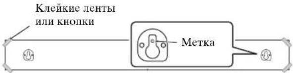
2 CHINMITE WABLOH DnA KpenJIeHnI B VBePHNTE MHeIOUeCBA PpOdaXe CaMoPe3bIB NOMEeHHbIX MECTax.
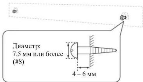
#
TTo6bI npIOJXHTb Ka6eHN HAn HcHTpaJIbHOH cHCTCMOH,cm.
PpABYIO KOJOHky.
3 HabecbTe ueHtpaIbHyIO cnCTeMy, BCTaBnB camope3bl B na3bl Ha ee 3aHne Yactn.
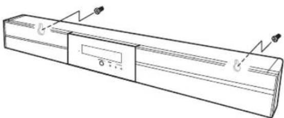
Ppokka Ka6eNe Hnd ceHTpaIbHOH cnCTeMoI
YTo6bI IpoNcyTHTb Ka6eJH BBePx, NOTpe6yeTcYcTaHOBnTb IOKJIaIKn DIIy OBeCIIeHHeHHIPOCTpaHCTBa II03aIN CEHTpaJIbHOH CNTEmbl.

BⅢaRe 2 JIeBOH KOJIOHKN BbIIIOJIHNTe CJJeYIOIIIE JeCTBn.
2-a: IIpHKpeIITe IIpIIaIarMaBIE IIOKJIaIKN K 3aIHeI IaHeJIN IeHTpaJIbHOI cHCTeMbI C IOMOIIbIO IIpIIaIarMCbIX JByCTOpOHHX KJIeKNX JIcHT. MoKHO BbIbpaTb JIn6o cToPOHy A, JIn6o cToPOHy B.
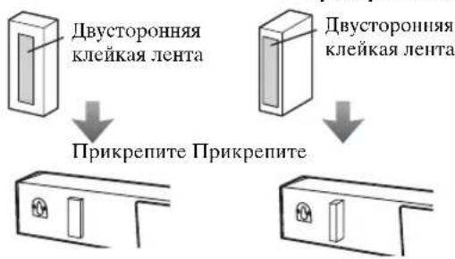
A: y3Koe npoctpaHCTBO
2-6: CHHMMTE IIa5IOH IJI KpeIIeHHN I BBePHHTe HMeIOIINecB IIpoJAAke camOpe3bI B IOMeueHHbIX MecTax.
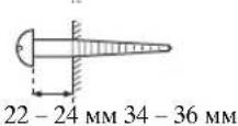
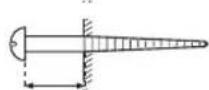
YctahOBka ceHTpaIbHOI CNCTeMbIC NOMOsbIO OTBepCTN IOI camope3bl
Iy cTaHOBKn IeHTpaJIbHOH CNCTeMbIC NIOMOIIbIO HMeIOIIHXcB IIpoJaXe KPOHIITeHOB HIN CTOeK MOxHO TaKKe HcNOJIb3OBaTB BHyTpEHHne H HApYXhIe OTBepCTHn IOI caMOp3bHa ee 3aIHHe YactH.
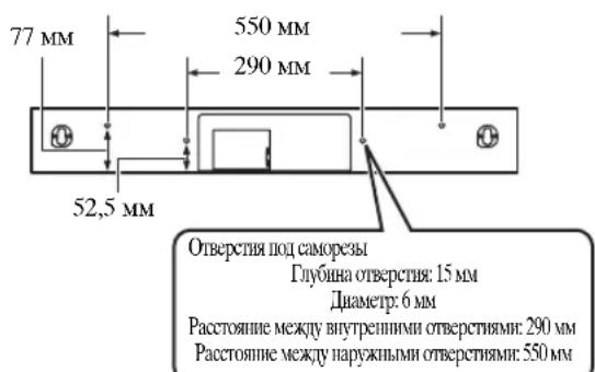
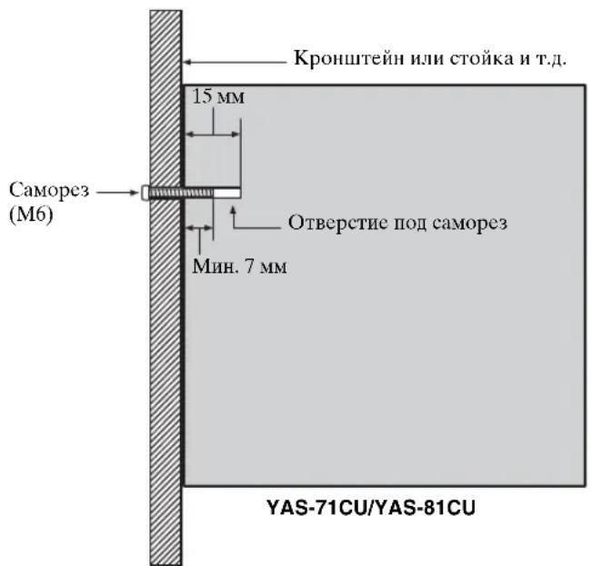
PnmeuHn
- IeHTpaJIbHaIcIcTeMa IJY YAS-71 BeCNT IIpH6JI. 5 KI N 6 KI JIA YAS-81. IIpIKpeIIITe IeHTpaJIbHyIO ChCTeMBI K KPOHIteHy, cToKHe HIN cTeHe. He yCTaHaBJIbHaIte IeHTpaJIbHyIO ChCTeMy Ha cTeHe, cJIeJIaHHoI IN3 HeIIpOvHbIX MaTEPhaIOB, HAIpHMep IIITyKaTpyKn HIN fAHebpI. 3TO MOKe IpHBecTH K IaJIeHHIO IeHTpaJIbHOI ChCTeMBI.
- NcnoJIb3yIte HmEIOIIeC8 B IpoJaKe caMope3bl, KOToPbIE MOrY T BbIepeKaTb Bec YcTaHOBJIeHHOH CHTeMBI.
- O63aTeJIbHo HcHIOJIb3yIte yKa3aHHbcI caMope3bl JIN KpeJIeHHN IeHTpaJIbHOH cHCTeMbI. HcHIOJIb3OBAHHe JpyHX KpeIeJKe, KpOME yKa3aHHbIX caMope3OB, HApIMep 6oJIee KOpOTKHX caMope3OB, rBO3Je IIN DBycTOPOHHe KJIeIKOH JeHTbl, MoKET IIpNBecTI K HaJIeHHIO IeHTpaJIbHOH cHCTeMbI.
- IIpn IIOKJIIOHHeHH HeHTpaJIbHOH CnCTeMbI HeO6XoDnMo 3aΦHKcHPOBaTb Ka6JIH KOJIOHOK B Tex MecTx, rIe OHN CBO6OHO CBnCAIoT. EcJIN BbI HcuaHHIO 3aIeHCTe IIpOBcaIOIH KAc6JIb KOJIOHKn HOrO HJIN pyKOH, ICHTPaJIbHaCnCTema MOKcT YIhactb.
IocyeyTaHOBKn IeHTpaJIbHOH CnCTeMbI, IpOBepBe HaJeXHoCTbe KpeJIeHHa. YamaHa He 6yTeT HcTH HHKaKoOTBCTCTBCHIOCTN 3a JIObIe IecchAcTHeClyuH, BO3HNKIIHc B peyJIbTaTe HpApBbHOH yTaHOBKn.
COEINHEHNA
He nodknouaHTe ka6bI nTaHn, noka He 3aBepueHb BCE noDKJIuOeHn.
-He npnlaarate n3nnuHnx ycui npn BkIIOueHnn uTekepa Ka6eJ. 3To MoKet npNBecT N NOBpeXdHIO uTekepa Ka6eJn nn pa3bema.
IopKIOueHne ceHTpaJIbHOcTeMbI n ca6Bypepa/6loka ynpaBJeHHa cncTeMoJ
BbIIOJIHITcIeIyIOUyIO IPOUeIpyI IIOIKIIOUeHHN IEHTpaJIbHOI cIcBvpepa/6IOka yIpaJIeHHN cIcTeMOI. IODKIIIOUeHHne Ka6eNe KOLOHOK
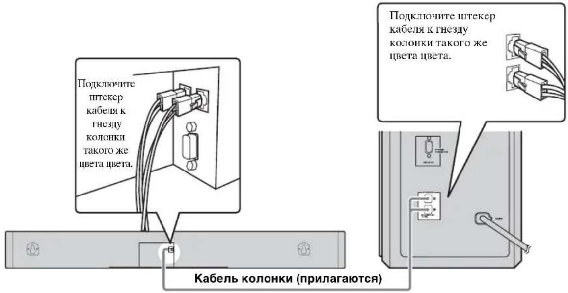
IopKnIOueHne Ka6eJy npaBJIeHn CnCTeMoI
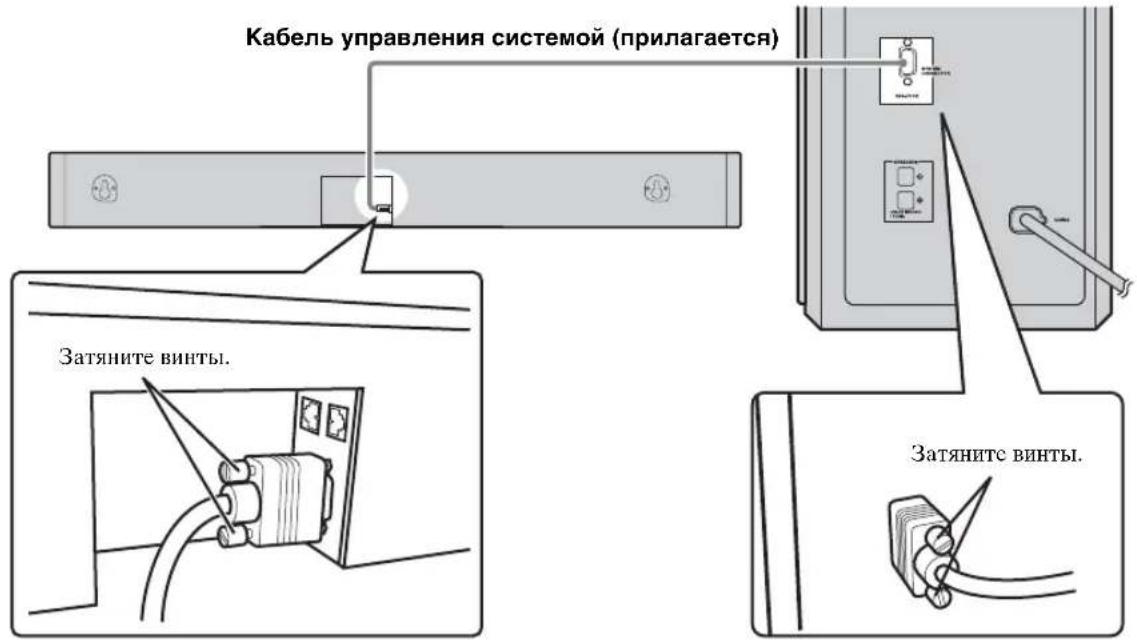
BnEOMaHHTOfoH HIN BnEOKaMepa H T.I. He ObOpyIOBaHHbIe IINΦpOBbIM BbIXoJOM.
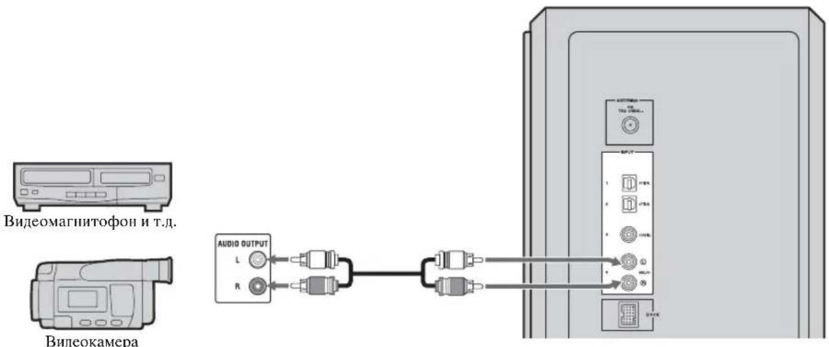
1 Haxmte KhoNky POsiTION, TTo6blpeynBpeXIMNoIOKeHnA.
Tekyiiee IOJIOKeHne OTO6pa3HTcHa JnCJIeE IpepeHHeI NaHeJN.
2 Haxmte KhoNk </, YTO6bI CdBnHyTb ONTMajbHyIO 06JNaCTb npocnyuBaHn (L6, L5, L4, L3, L2, L1, CENTER, R1, R2, R3, R4, R5, R6).
HactpoTe 3HaueHHn OHTMaJIbHOJ o6JaCTn IpcIyUHHBaHHn OT L1 Do L6,ecJIN IOLOXeHHne cIyIIaTeJI HaxOHTcra CJeBA OT IeHTpaJIbHOJ CnCTEmbl, HAcTpOte 3HaueHHn OITMaJIbHOJ o6JIaCTn IpcIyUHHBaHHn OT R1 Do R6,ecJIN IIIOJOxHe nClyuATeJI HaXOHTcra CnpabaOT IeHTpaJIbHOJ CNCTeMBI.
IIOJoxKeHHe OTo6pa3nTcHa IINCIIe IpepeHHe IIaHeJI.
POSITION L1
Ппимер: "POSITION L1"
3 CHOBA HAXMITE KHONKY POSITION JIN ENTER, YTO6bl BbIITN 13 peXUMa NOJOKHeH.
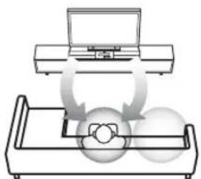
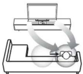
OnTmAbHn o6NaCT npocnyuBaHn

-HactpoKa H yMoJIaHnIO:CENTER.
- EcnH NocJe BbIIOJIHeHH Hra 1 HaKaTb KHOHky TEST, cHCTeMa BbIaCT TcctOBbI cHrHaJI dJIbBnpyaJIbHO IeHTpaJIbHO KoJOHKn, YTO6bl MOxHO bblIO BblIOJHHb HAcTPOKn IIIOJXcHH. (cTp.20)
3Ta HAcTpoKa coXpaHReTcraBCEx HCTOHTHKOB BBOJa.
3TaФyHKINHIOCTYINHJaIaKe IINBbIKIOHHeHHOMpeKHMoe6bCMHO3ByaHHN.
PpimmeaHne.
EcHIOcIe BXoJa BpeKHM IOJOKeHHB TeYeHHe 30cekyHHe HcHIOJIb3OBaTb 3y fyHKnIO, CnCTema ABTOMATHEcKHN BbIIeT H3 peKMa IOJOKeHH.
Bb6op onTmMaIbHoi oIpaCTn npocnyuBaHn
OITHMaJIbHyIO OJlaactb IPOcIyIHHBaHnM OMOKHO BbI6paTb B DByx peKImax.
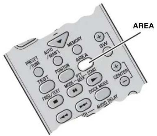
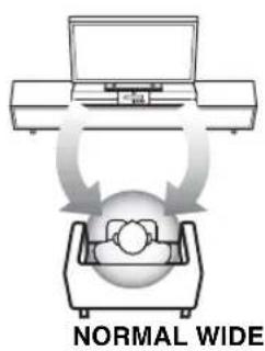
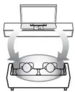
HaXmTe KhONKy AREA.
Pn KaKJOM HaKaTHN KHOIIKN AREA IIIOIepMeHHO BbI6paIOTcpeKIMbl NORMAL IN WIDE.
NORMAL
Bb6epHe TaHHbI IapaMeTp JyuchJIeHH 3ByKOBOrO eΦeKTa.
Пи Вьборе ржma NORMAL HaJINCHJIe IpeJHHeI HaHEJI NIOBHTcR HJINKaiuNRA "AREA NORMAL".
AREA NORMAL
WIDE
Bb6epHTe aHHbI IapameTp IJIpaHHeHHOITHMaJIbHOJIOlaCTN IpocIyHHBaHH.
中
-HactpoKa IIO yMoIuaHnIO: NORMAL.
-TaHaCTpoHka coXpaHaeTcIJIbBceX HcTOUHKnOB BBOJa.
PpimMeaHne.
Ta OhepaHnIOCTyHnToTbKO Ipr BkHOueHHOMpeXHMe 06bEmHoRo 3ByaHn.
IpeekJIOUaET TIN IporpamMbI.
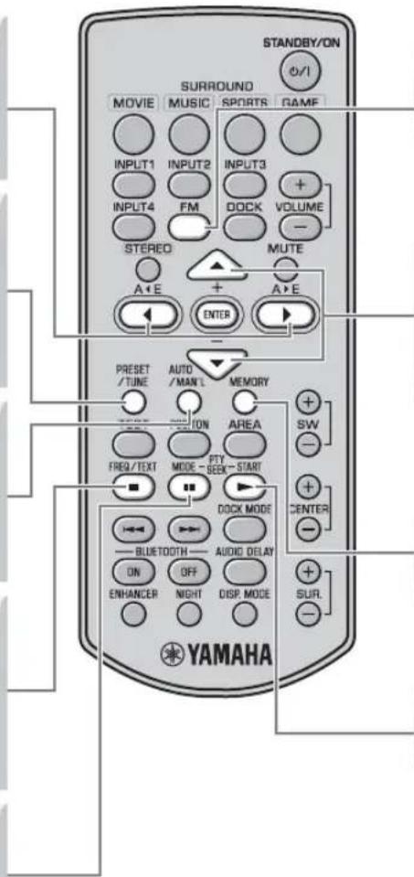
FM
3aetaeFMBkaueCTBe BBOda.
+/-
BbIbIpaCT Tpe6yEmyo HactOTy B pexHmC HactpOKN HaCTOTBI.
BbIbpaertpe6yEmbHIOmePpeBapHTeJIbHOHaCTpOKn (ot 1do8) BpeXnMe IIpeBapHTeJIbHOHaCTpOKn.
MEMORY
AKTHBHPyETpeKHM IIpeBapHTeJIbHbIX HAcTPOEK N3 PAMrTH.
PTY SEEK START
3aynckae TnCK Tnna nporpaMbl.
OchOBhble onepaunn hactpoiKn
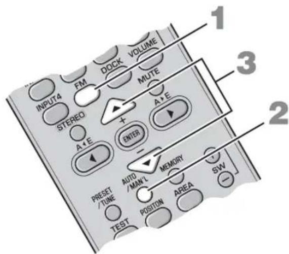
1 Haxmte KhoNky FM, yTo6bl BbIbpaTb KaueCTBe BbOda FM.
“FM”noBHTcHaJINCJIeepedHeiNaHeJN.

2 Haxmte KhoNky AUTO/MAN'L, YTo6bl NepeKIOUHTbcM MeKdy aBTOMaTnueCKM m pyHbIM peKHMAMn.
PnIpeKJIIOUcEHNN CnCTeMbI BpeXHM aBTOMaTHuecko HaCTpOKn 3arOpHTcN HnIKatop AUTO.
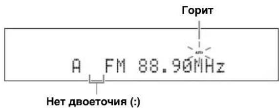
中
EcHIOrO6paKaTcIbOcToUHe(:),CHCTMa IIpeKJIIOueHaBpeKHMIIpeJBapHTeJIbHOHaCTpOHN. (cTp.24)
3 Odn pa3 haxmte KhoNky +/-, YTo6bl Haatb aBTOMaTHueCKyHacTpoNkY.
Korla cnctema HactponTcH a cTaHIO, 3aropntc HnHKaTOp TUNED nHa nnCIIee IepedHeI HaHeJN OTo6pa3HTcYacTOra IIpHHMaEMOc TAHIN.
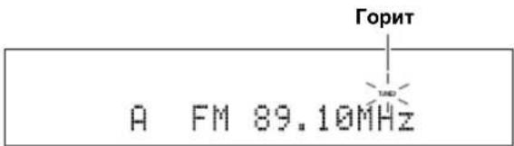
中
IIpn HacrpoKe Ha FM-ctaHINIO B aBtOMaTHHeCkOM pexKHMe cHcTeMa IIpHHMaET paJInocnHaJI FMCTaHININ BpeKHMe cTepeOIIpHema. Ha IInCeIe HepeHHe HaaHeJN OTO6pa3ntc HInKaTOp STEREO.
PyHnHa HacTpoKa
EcHn CnHaJI CTAHIN, KOTOpYIO Tpe6yeTcBbIpaTB, CJINIKOM CJIa6bI, TO HAcTpOHTbcra HaHyKHyIO CTaHIIO MOXIO, yKa3aB YacCTOTy BpyHIVIO. BpeKHe HAcTpoKN Ha FM-CTAHIO, HAKHMATEKHOIIKY AUTO/MAN'L, IOKaHHNKATOP AUTO He Ncue3HET c JINCIIEe, a 3aTeM C NMOIIbIO KHOIOK +/- yKaXHTe YacCTOTy Tpe6yeMoI CTaHIIN.
Pn HacrpoKe Ha cTaHIO C NMOBIO FyHKIN
pyHn HAcrpoKn ChTeMa PnHMAeT CNHaJIbI
FM-CTaHn B peKHMe MOHOOHueCKO
IIpHema IJI IOBbIeHna KaeeCTBa CNHaJa.
IcnoIb3OBAHne yHKnnpaBapntbHOHaCTpOKn Ha CTaHcN
■Avtomatnuecka npedBapntbHa nactpoKa Ha cTaHcN
Moxho coxpaHTb 40 FM-ctaHn (oT A1 IIO E8: IIO 8 Homep IpeBapnteJbHOH HAcTPOKn B KaKdoN 35 rpynn).
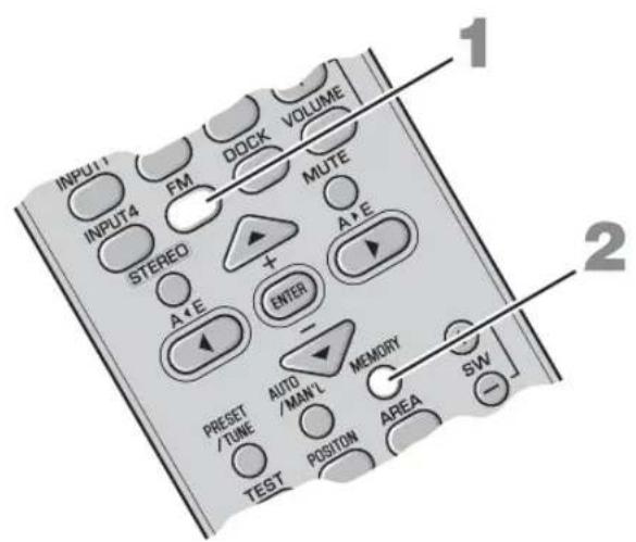
1 Haxmte KhoNky FM, YTo6bl Bbl6paTb B KaueCTBe BBoDa FM.
“FM”IOBHTcH Na IINCIIe IpepeHnIaHeJH.
2 HaxmTe udepXnBaIe KhoNkY MEMORY 6oJee 3 cekyHd.
HaHyT MInTaB IpyHua HOMepIpeBaPteJIbHOHacTpOa, a TaKke HINJkaTopbI MEMORY H AUTO.CuYcTbIpH6JIIN3HTeJIbHO5ceKyHJaHauHETcIpoJeypa aBTOMaTHuecko HAcTpOaKN,HaHHaC TekyiEe YactOTbIB HaIPaBJIeHHN BO3paCTaHHa YactOT.
YTO6bI OTMeHHTb OIIepaIHIO,CHOBa HaKMITE KHOIKY MEMORY,KoFJa MHaTaET HnHKaTOp MEMORY.
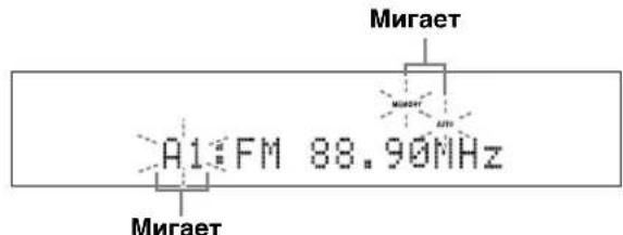
IIO 3aBepHCHHH aBTOMaTHUeCKo IIpeJbapHTeJIbHO HAcTPOHKn Ha IINcIIe eIpeHHe NpHEn OTO6paXkaeTcay AcToTa IocJIeHHe IIpeJbApHTeJIbHO HAcTPOEHIHO cTAHIN.

HaKMTe KONKY A E INA E, TTo6bI Bb6paTb rpynnI ppeBapHTeJbHOH HAcTpOKn, a 3aTe m C HOMOIIIO KHOIOK +/ - BB6cpHTc HOpE IpeBapHTeJbHOH HAcTpOKn, II ON KOtOpbIM 6yIET coXpAHena IIepBaI cTAHNIA IOCLc BbINOJIHeHHN IIIaRa 2.
PnmeuHn
- IIpn coxpaheHHH HOBON CTAHINH IOI TEM Xe HOMepo IpeBapHTeJIbHOH HAcTPOKHNIOH OIOH NHomepOM JaaHHBe CTAHINH YdaJIHOTcR.
- ECIN KOJHueCTBO IIpHHMaEBx CTaHIH He IIpeBbIIaET 40 (OT A1 Do E8), TO yHKIIa ABROMaTHueCKO IIpeBaHPcJIbHO HAcTPOIKN OTKIOUAcTe IocIe 3aBepHcHn IOHcKa Bcex HMeIOHxCs CTaHIH.
Ecn Tpe6yemar cTaHnHa He coxpaHcHa Hn COxpaHcHa B HeIpaBnIbHyO rpyHny Hn He IIOJ Tem Homepom, BblIOJIHNrCe IpeBapHTeJIbHyO hAcTpoNkY Ha 3Ty cTaHIIIO BpyHyO. IOpnp6Hcc cm. pa3JeI "PyHna IpeBapHTeJIbHnA hAcTPOKa cTaHnn" Ha cTp. 25.
■PyuHa npeBapnteHbHa HaCTpoKa cTaHcN
NcnoJIb3yIte 3Ty fynKnHIO JIA pyHNO IpeJBapHTeJbHO HAcTPOKn HA Tpe6yeMyIO cTaHIIIO.
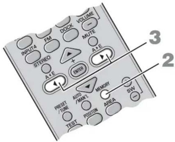
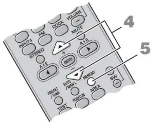
1 BbInonHnTe HacTpoKy Ha cTaHcIIO.
HctpykuHIO HAcTPOKe cm.Bpa3eJe "OChOBhIe OpeaHn HacTPOKn"Ha cTp.23.
2 Haxmte KhoNky MEMORY.
B TeueHHe npH6JIH3HTeJIbHo 30 cekyHnHa HncIJIee IpeEne HnAHeJIn 6yTeT MnTaTb INHnKaTOp MEMORY.
YTO6bI OTMcHHTb ONcpaIIIO,CHOBa HaxMHTe KHOIIKY MEMORY,KoTJa MInact INHINKaTOP MEMORY.

3Korda muraet nHdkaTop MEMORY, c NOMOsbIO KHOJOK AE BbI6epNTe rpynny npedBapntelbHoi hacTpoiKn (OT A do E).
OTo6pa3HTcBbI6paHHaIpyIIa IIpeBaHTEJIbHOHaCTpOKn.
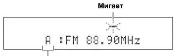
Ppynnn npedBapnteHbno HacptpoKu
4 Korda muraet nHdkaTop MEMORY, Haxmte KhoNk+/-, yTo6bI Bbl6paTb Homep npedBapnteJbHoH hAcTpoKn (OT 1 do 8).
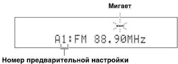
5 HaxmTe KhoNky MEMORY nna NOtBepKdEHHn PpeDbaPteJIbHOH HAcTpoKn.

IocJe IOBJIeHnHa IINCIJIe IepeJHe IIaHeJI INHIIKauuN “A1:PRESET OK”, Ha HeM OTo6pa3HTcra 3HaueHHe YactOTbIC BbIOpaHHoR rpyIIOI ppeBaHPteJIbHOH HAcTPOIKN.C IINCIJIe IepeJHe IIaHeJI INCye3HEr HHNKATOP MEMORY.

PnmuMeaHn
IIpncoxpaHeHHHOBOcTaHINHIOIeTMJKeHOMepoIMpeBapHTeJIbHOH HAcTPOHNIIOb6IE HMeOINHecrIOIOTHMHomepOMHaHHBeCTaHHINyJaJIYOTcR.
BMeCTe c aactoToH cTaHHuTTaKKe coxpaHHeTc3HauchHepeKHMnIpHcMa (Ctepeo HINMOHO).
BbI3OB npeBapntbHo coXpaHeHHbIX CTAHcN
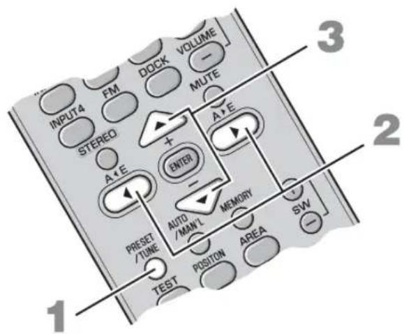
1 Haxmte KhoNky PRESET/TUNE aBbIbopa pexima npedBaPntelbHOn HactpoKn.
2 C nOMOsbIO KHOJOK A
3 C NOMOJIbIO KHOJOK +/- BBI6epNTe Tpe6yEMbl HOMeP npEaBapnteJIbHOn HacTpoKn (OT 1 do 8).
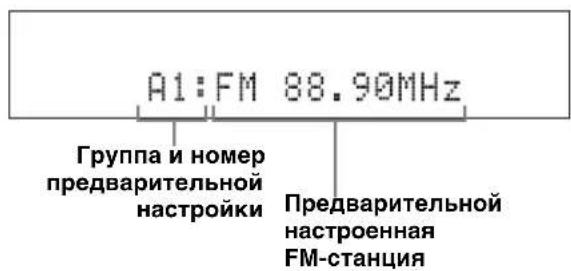
PpneM paNocTahn C cnHaJOM cnCTembl paNODaHHbIX
CnCTema paHIOHaHHbIX - 3TO CnCTema IpeJaH JaHHbIX JIa CTaHIM FM, KOtOpA HcIOb3yETcBO MHOrHX cTpaHax. CnCTema MoKet IIpHHMaTH HfOpMaIIHIO CnCTembl paHIOHaHHbIX, HApHMeP PS (Ha3BaHHe cTaHIN) IN PTY (THI nporpaMMbl), RT (paHIOTeKcr) IN CT (BpEm) IIpn IIpHeme paHIOBeIaTeJbHbIX paHIOOCTaHIN CnCTembl paHIOJaHHbIX.
IpeeknoueHne HOpmaunOHoro DnCnIe npn npneMe paAnocTaHcN C nRHaIOM cnCTeMbI paAnOdaHHbIX
Bo BpemI npHema paAnocTaHnI c cnHaJOM cnCTeMbI paHNOaHHbIX HaxMMTe KHOKNy FREQ/ TEXT. IIpi KaKIOm HaKaTHN KHOKN TeKCTOBbI INcIIJIe I3MeHHeTcIJeIyIOHN M6pa3OM:
$$ \rightarrow \mathrm {P S} \rightarrow \mathrm {P T Y} \rightarrow \mathrm {R T} \rightarrow \mathrm {C T} \rightarrow \mathrm {F R E Q U E N C Y} $$
TnHOpmaun
PROGRAM SERVICE (PS) OTo6paXeHHe IprHHMaemB HacToaIIIM MOMeHT IIPOrpaMMbI CnCTeMbI paIHOnaHHbIX.
PROGRAM TYPE (PTY) OTo6paKeHHe TnHaI pInHMaemOB B HAcTOraIIIM MOMcHT IporpaMMbI cHCTeMbI paINoJaHHbIX.
-RADIO TEXT (RT) OTo6paXeHnE HnΦopMaIIHnO IIpHHMaCMoB B HaCTOaIIM MOMeHT IporpaMMe CHCTeMbI paJIOJaHHbIX.
CLOCK TIME (CT) OTo6paXeHHe TeKyuIero BpeMeHH.
FREQUENCY OTo6paKeHHe qactOTbI, rpyIIbI IIpeBapHTeJIbHOH HAcTpOKn HOMepa.
PnmuMeaHn
MooHbBb6paTbOHH3pcKHMOBOTobpaXeHHa CHCTeMbI paHIOHaHHbIX TOJIbKO B TOM cIyuae,ecIH Ha HcHJIeepEHN He NaHeJIN 3aTOpHTcCoOTBeTcTBYIOHN HIKaTOP ChCTeMbI paHIOHaHHbIX.IIra IIpHcMa Bcex DaHHbIX ChCTeMbI paHIOHaHHbIX OT cTaHIIIM MOKeT IOTpe6oBaTbcr HeKOTOpoe BpeM.
-MoJHO BbI6paTb ToJIbKO peKHMbl OTO6paKeHHcHCTeMb paIHOnaHHbIX, o6ecnueHbAcMbI cHaHHo cTaHHnc.
-ECINI INHIMMaEMBIE CHTHaJIbHEIOCTAOTHO CHJIbHI, CHCTeMe, BO3MOXHO, HC yIaCTc HIOJIb3OBAbT DAHHbIC CHCTeMbI paHIOHaHHbIX. B YAcTHOCTH, IINpeKHMa RT Tpe6yETc 6oJIbIIIOE KOJInueCTBO JAHHHIX IN OH MOKeT 6blt HeIOCTyIeH daKe B TOM CIyUae, ecnIOCTyIHbI npYrHe peKHMbI OTO6paKeHHN CHCTeMbI paHIOHaHHbIX.
BcIyue IIOxOro IIpHema HaxMMrte AUTO/MAN'L 118 BbI6opa pyHoi HacrpoKn. (rCtpr.23)
-ECIN BO BPEMa IPhEma CnCTeMoJ DaHHbIX CnCTeMBI paHIOaHHbIX CnTHaJI OCJA6JIeH BHEIHHMN IOMExAMII, HPHcM MoKcET 6bITb HEOXHNaHHO IIpePBAn, a Ha INCHIEe IpeJeHe NpHeJI N OTo6pa3HTc HINKaTOp "...WAIT".
EcIN BB6paH peKHM RT, KOJIHyecTBO 6yKBHeHHIOHΦPOBbIX CMBOJIOB, HCHIOJIb3yIOUHXcI, HIOOT6paXCHIIH HΦOPMaUN O IIporpAMMC, IIC MOXCTIpeBbIaTb 64 CMBOJa, BKIOUaY CHMOJI yMIAyTa. HcIOHcyTHMbIc CMBOJIb 6yIyT OTo6paKaTbCn IOIDcPKBAIHcM“
- Ecnn npnem npepban B pexnme CT, ha nncnnee nepeDnei naheJn oTo6pa3ntcra "CT WAIT".
BbI6Op cTaHcHn no TnHy nporpamM (XaHp)
MOxH0 HAcTpOHTb paHIOCTaHHn C cnHraJOM
cnCTeMbI paHIOJaHHbIX, BbI6pAB TnII IporpaMM (kaHp)
13 15 BapHaHTOB. PocJe BbI6opa TnIIa IporpaMMbl
cnCTema aBTOMaTHueCKN BbIIIOJIHN TIOHCK
paHIOCTaHHn C cnHraJOM CNCTeMbI paHIOJaHHbIX,
IpePaIOUHX COOTBeTCTBYIOHN TNI IporpaMMbl.
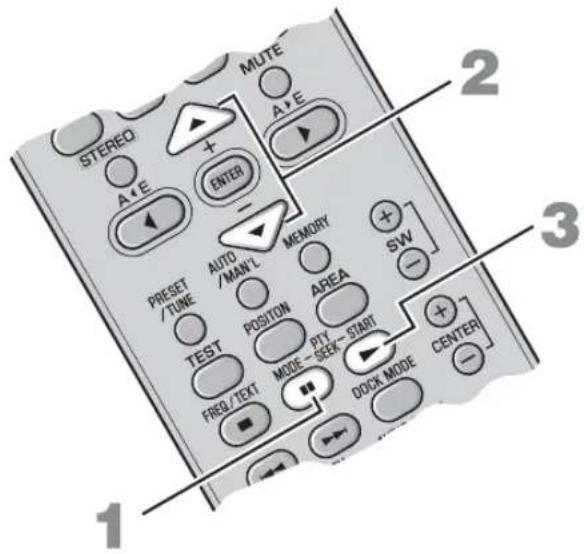
1 HaxmTe KhoNky PTY SEEK MODE, yTo6bI nepeKIOuHTb cncTeMy B pexm PTY SEEK.
Ha nHcJIeC IepcIHcHn HAcHJn HaUHeT MHRaTB TnI npOrpaMMbI HIN "NEWS".


YTO6bI BbHn H3 peKmMa PTY SEEK, cHOBa HaKMHTe KHOIIky PTY SEEK MODE.
2 C nOMOJIbIO KHOJOK +/- Bbl6epNTe TnnporpaMMbl.
Ha nncnnee nepeHne naHeJn oTo6pa3ntcna3BaHHe BbI6paHHoro Tnna Iporpambl.
TO6bIOCTaHOBHTIOHCKCTAHINCHOBaHaKMHTe KHOIIky PTY SEEK START.
PnmeuHna
CnCTcMa 3aBcPHTIIOCK TAnHII IprObHApYKCHINCTaHHH,IEpeiaIOeB bI6paHHBI THI IporpAMMBI.
EcHnObHApyKeHHa cTaHnHHe IOHXoHHT,CHOBa HAnKMHTe PTY SEEK STARTIJI BA03o6HOBJIEHHNIOHcKa IpyrO cTaNHH,IIpeDaIOHc TaKOH Kc TINI IpOrpaMMbl.
ИСПОЛьЗOBAHNE ДОПОЛHINTEЛьНОGOБOPУДOBAHЯ
Испобзоване iPod™
Iocne yctahOBKn iPod ByyHBepeCaJIbHyIO JOK-CTaHcHIOYamaha iPod (Haipnmep, YDS-10/YDS-11, npno6pcTaecrOeJIbHO),IOJKNIOUeHHyIO Kpa3bemy DOCK ca6Bypepa/6IOka ynpabJIeHnncHTcEmoI (cTp. 14), MoXHO HauaTB BOCIIPOH3BcJeHnnc iPod.
PoeepKnBaemble MoJeN iPod
iPod (Click and Wheel)
iPod nano
iPod mini
iPod touch
ФункцяЗардкбатapeste
Korla 3a chtema BkHueHa, OHa IIO3BOJAE TapXaTb 6aTapeo IIeepa iPod, yCTaHOBJEHHORO ByHnBepcaJIbHyIOK-CTAHIOYamaipod,IOIKJIooeyHHyO K pa3bemy DOCK ca6Bypepa/6IOka yIpaBHeHH cHcTeMOI.
YctaHOBka nIeepa iPod ByyHnBepcaJbHyIO dOK-CTaHcNIO Yamaha iPod
IocJIe ycTaHOBKn IIeepa iPod ByyHBePcaJIbHyIO JOK-CTaHIIHO YamaHa iPod Ha IINcIIee IpeEHN He NaHeJI INoBHTc HnIkaIgna "iPod connected" n DOCK.
PnmeaHna
- JIJI HeKOTOPbIX MoJIeJIe HIN BepCNI IPOrpaMMHOrO o6ecIeueHHI iPoD MOrYr 6bITb HeIOCTryHbI OIIpeJeIeHHBIE cyHKUHN.
IIOJIbIcIcKcoO6HHeHHoCocToHHH, KOtOpBle OTo6paKaOTcH a HcHJIe IpeDHe IIaHeH, cM. B IIyHKTe "iPod" pa3JeJa "Bo3MoKHbIe HeHCIPaBHOCTn ChOCobIx yCTpaHEHH" Ha cTp. 36. - Ipeepy cTaHOBKOH HIN H3BJeHHeM PIIeepa iPod o6raTeJIbHO cHHKaIte YpoBeHr pOMKocTH IO MHHMyMa.
Oprahbl ynpablenn n yHKcnn iPodTM
YIpaJIeHHe IIEepom iPod moXHO ocYIIeCTB Jb B IIpoCTOM yJaJIeHHOM peXHMa HIN B peXHMe IIPOCMOTpa MeHIO.
中
IpeKIOaTbC MekJy IPOCTbIM yJaJIeHHbIM peKHMOM HIN peKHMOM IPOCMOTpa MeHIO MOKHO C IIMOIIbIO KHOIIKN DOCK MODE.
DOCK
3aact DOCK B KaueCTBe BBOJa.
KhoNk ynpaBHeHn BocnpOn3BeDeHnem
YIpaBIAJOT BOCIIPOIN3BeJeHHeM IOIKJIIOUeHHORo iPod.
IpeekJIOUaEt MeKJy IPOCTbIM yJaJIeHbIM peXHMOM HIN peXHMOM IIPOCMOTpa MeHIO.
KaKbI BapHaHT MOXHO BB6paTb C NMOUBo KHOKN ENTER.
Bb6epnte "Off"TTO6blOTKIOOHHTb3TydyHKIIO.
- Bb6epHte "One", YTO6bI 3aIaTb IOBTOPHc BOCIIPOHN3BeJeHHe OJIOH KOMIO3HH.
- BbI6epHTe "All", TTo6bI 3aIaTb IOBtOpHoe BocIpOnHBeJeHHe rpyIIbI KOMIO3HIIH.
PpimmeaHne.
CoepKHMoe MeHIO IIeepa iPod 3aBnHT OT MoEJI IN IIN IOKOJIeHHI IIeepa.
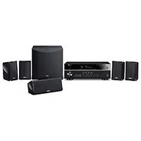
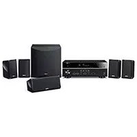
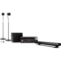
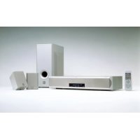
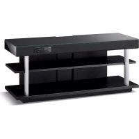
- Caution: Read this before operating your unit.
- WARNING
- ■For U.K. customers
- Note
- Special Instructions for U.K. Model
- IMPORTANT
- CONTENTS
- INTRODUCTION
- PREPARATION
- BASIC OPERATION
- OTHER FUNCTIONS
- USEFUL OPERATION
- ADDITIONAL INFORMATION
- ■Introduction
- ■About this manual
- GETTING STARTED
- Supplied parts
- ■Units
- ■Accessories
- Controls and functions
- ■Front panel of the center system
- ①Front panel display
- ②Remote control sensor
- ③Power indicator
- ④STANDBY/ON
- ⑤INPUT
- ⑥VOLUME-/+
- ■Front panel display of the center system
- ① Decoder indicators
- ②DOCK indicator
- ③ENHANCER indicator
- ④NIGHT indicator
- ⑤ Tuner indicators (AUTO/TUNED/STEREO/MEMORY)
- AUTOindicator
- TUNED indicator
- STEREO indicator
- MEMORY indicator
- PTY HOLD indicator
- PS/PTY/RT/CT indicator
- ^ 6 M u l t i ~ i n f o r m a t i o n ~ d i s p l a y
- MUTE indicator/VOLUME indicator
- Remote control
- ①Input buttons
- ②STEREO
- ③ Cursors (▲/▶/▲/▼)/ENTER
- PRESET/TUNE, AUTO/MAN'L, MEMORY
- ⑤ ////11//
- ⑥ BLUETOOTH ON/BLUETOOTH OFF
- ⑦STANDBY/ON
- ⑨VOLUME (+/-)/MUTE
- SW (+/-) /CENTER (+/-) /SUR. (+/-)
- ①DOCK MODE
- ⑫POSITION
- 13TEST
- FREQ/TEXT
- PTY SEEK MODE
- PTY SEEK START
- ENHANCER
- 16NIGHT
- ⑦AREA
- ⑱AUDIO DELAY
- DISP. MODE
- Using the remote control
- Notes
- ■Installing the batteries
- PLACING THIS SYSTEM
- Center system (YAS-71CU/YAS-81CU)
- Subwoofer/system control (YAS-71SPX/YAS-81SPX)
- Placing the center system
- Placing the center system beneath/under a TV
- ■Attaching the center system to a wall
- Installing the center system using the keyholes
- Installing the cables above the center system
- Installing the center system using the screw holes
- CONNECTION
- Connecting the center system and the subwoofer/system control
- Connecting external components
- Digital connection
- [INPUT 1, 2] OPTICAL jack
- Example 1: DVD player
- Example 2: TV game console
- ■Analog connection
- Connecting the Yamaha iPod universal dock
- Connecting the Yamaha Bluetooth wireless audio receiver
- Connecting the indoor FM antenna
- Connecting the power cable
- 中
- Press STANDBY/ON.
- 2Press one of the input buttons to select an input source.
- 3Start playback on the selected external component.
- Press VOLUME + / - to adjust the volume level.
- Now, try various features of this system!
- Using various sound features
- Enjoying FM broadcasts/ optional equipment
- AIR SURROUND XTREME
- What is AIR SURROUND XTREME?
- ■Virtual 7.1 channel
- Listening to surround mode of AIR SURROUND XTREME
- Press one of the surround mode buttons.
- Surround mode descriptions
- Movie
- Music
- Sports
- Game
- Shifting the optimum listening area from side to side
- Selecting the optimum listening area
- Press AREA.
- NORMAL
- WIDE
- Checking the virtual surround effect
- Press TEST to output the test tone.
- Using extended stereo mode
- Press STEREO to enter extended stereo mode.
- EXTENDED
- #
- Setting compressed music enhancer
- Press ENHANCER.
- LISTENING TO FM BROADCASTS
- Overview
- Frequency tuning mode
- Preset tuning mode
- Controls and functions for the FM tuning
- Basic tuning operation
- Manual tuning
- Press FM to set the input to FM.
- Press AUTO/MAN'L to switch Auto/Manual.
- Press +/- once to begin automatic tuning.
- Using station preset feature
- Automatic station preset
- Manual station preset
- Tune into a station.
- 2Press MEMORY.
- Press A< E or A> E repeatedly to select a preset group (A to E) while the MEMORY indicator is flashing.
- Press +/- to select a preset number (1 to 8) while the MEMORY indicator is flashing.
- Press MEMORY to confirm the preset.
- Recalling the preset stations
- Receiving Radio Data System stations
- To switch the information display of Radio Data System
- Information type
- To select stations by program type (genre)
- Press PTY SEEK MODE to set the system to PTY SEEK mode.
- Press + / - to select the program type.
- Press PTY SEEK START to start searching for all the available Radio Data System preset stations.
- USING OPTIONAL EQUIPMENT
- Using iPodTM
- Supported iPod
- Battery charge feature
- Stationing your iPod in the Yamaha iPod universal dock
- Controls and functions for iPodTM
- ■Controlling your iPod in simple remote mode
- ■Controlling your iPod in menu browse mode
- Press DOCK MODE to enter menu browse mode.
- Press / / repeatedly to select the desired menu, and then press ENTER to play back the selected song.
- Shuffle
- Repeat
- Using Bluetooth™ components
- Controls and functions for Bluetooth components
- DOCK
- BLUETOOTH ON/OFF
- Playback control buttons
- ■Pairing the Yamaha Bluetooth™ wireless audio receiver and your Bluetooth™ component
- Press and hold BLUETOOTH ON for more than 3 seconds to start pairing.
- Check that the Bluetooth component detects the Yamaha Bluetooth wireless audio receiver.
- Select the Yamaha Bluetooth wireless audio receiver in the device list of the Bluetooth component, and then enter the pass key "0000" on the Bluetooth component.
- ■Establishing a connection
- ■Disconnecting
- Press DOCK, and then BLUETOOTH OFF to disconnect the system from the Bluetooth component.
- ■Playing back the Bluetooth component
- LISTENING AT LOW VOLUME (NIGHT LISTENING MODE)
- Press NIGHT.
- ADJUSTING THE VOLUME BALANCE DURING PLAYBACK
- CHANGING THE BRIGHTNESS OF THE FRONT PANEL DISPLAY
- Press DISP. MODE repeatedly.
- Troubleshooting
- iPod
- Bluetooth
- Glossary
- ■Channel (ch)
- ■Dolby Digital
- ■Dolby Pro Logic II
- DTS
- ■PCM (Pulse Code Modulation)
- Sampling frequency
- Specifications
- YAS-71CU/YAS-81CU
- YAS-71SPX/YAS-81SPX
- Amplifier
- FM Tuner
- Subwoofer
- Other sections
- Limited Guarantee for European Economic Area (EEA) and Switzerland
- Conditions
- Information for Users on Collection and Disposal of Old Equipment and Used Batteries
- [Information on Disposal in other Countries outside the European Union]
- Note for the battery symbol (bottom two symbol examples):
- Prise [INPUT 4] ANALOG
- [INPUT 1, 2] OPTICAL-Buchse
- ■Analoger Anschluss
- STEREO-indikator
- ⑦MUTE-indicator/VOLUME-indikator
- Fjarrkontroll
- 16ENHANCER
- FM-tuner
- ⑦MUTE-indicator/VOLUME-indicator
- VOLUME (+ / - ) / MUTE
- DpyTne OyHKLIM
- IIPOCJYIINBAHNE FM-PAJIIOCTAHII 22
- HCHIOJIb3OBAHNE IOHOJHHTEJIbHOTOFOPYTOBAHIG 28
- NOJE3HbIE ONEPAUIN
- HACTPOINKA 3AIDEPKKIN 3BYKA. 32
- IIPOCJYIINBAHNE HA HN3KOM YPOBHE TPOMKOCTH (PEKHM HOHOTO IIPOCJYIINBAHNA) 33
- DONJHNTJIbHAR MHOPMALIN
- JOIOJIHHTJEbHAIHHΦOPMAIIN.35
- ■В蜱ейнe
- O6 3Tom pykoBODCTBe
- ②Инданкатор DOCK
- ③Инд�示Top ENHANCER
- ④ИнданkaTop NIGHT
- ⑤ INHdNkTopbl THepeA (AUTO/TUNED/STEREO/MEMORY)
- Hdukatop AUTO
- INdkaTOp TUNED
- ИндкаТОР STEREO
- ИндikaTop MEMORY
- HdkaTop PTY HOLD
- HdkaTop PS/PTY/RT/CT
- ⑥MHorofoyHKUHOHaBHBi DNcPJIeN
- ⑦ HndkaTop MUTE/mHdkaTop VOLUME
- NyIbT dy
- ①KhoNKn BBOda
- ③ Kypcopbi(▲/▶/▲/▼)/ENTER
- ④ PRESET/TUNE, AUTO/MAN'L, MEMORY
- ⑤ □/口/D>1K/□
- ⑥ENHANCER
- 18AUDIO DELAY
- IcnoJb3OBAHne npJIbTa Dv
- PnmeaHn
- YctahOBka 6aTapeek
- PnmuMeuHa
- PA3MEUHNE 3TOI CNCTEMbl
- ZeHTpaJIbHa cncTeMa (YAS-71CU/YAS-81CU)
- Ca6Byep/6JIOK ynpaBJIeHnCnCTEmoY (YAS-71SPX/YAS-81SPX)
- PnmeuHn
- Pa3MeueHne ueHTpaJbHOcCTeMbI
- Pa3meueHne ceHTpaIbHOcCTeMbI HenocpeDCTBeHHO NO TeLeBn3OpOM/NoTteLeBn3OpOM
- ■MOntax ueHtpaIbHOcCTeMbI Ha cTeHe
- YcTaHOBka ceHTpaJIbHOH cNCTeMbI C NOMOuIIO Na3OB
- PnKpEnTe npJaraembI Wab6NoH dN KpenJIeHnK CteHe n pa3MeTbTe No Hemy OTBepCTHa.
- CHINMITE WABLOH DnA KpenJIeHnI B VBePHNTE MHeIOUeCBA PpOdaXe CaMoPe3bIB NOMEeHHbIX MECTax.
- HabecbTe ueHtpaIbHyIO cnCTeMy, BCTaBnB camope3bl B na3bl Ha ee 3aHne Yactn.
- Ppokka Ka6eNe Hnd ceHTpaIbHOH cnCTeMoI
- YctahOBka ceHTpaIbHOI CNCTeMbIC NOMOsbIO OTBepCTN IOI camope3bl
- COEINHEHNA
- IopKIOueHne ceHTpaJIbHOcTeMbI n ca6Bypepa/6loka ynpaBJeHHa cncTeMoJ
- PpimmeaHne.
- Bb6op onTmMaIbHoi oIpaCTn npocnyuBaHn
- HaXmTe KhONKy AREA.
- FM
- +/-
- MEMORY
- OchOBhble onepaunn hactpoiKn
- Haxmte KhoNky FM, yTo6bl BbIbpaTb KaueCTBe BbOda FM.
- Haxmte KhoNky AUTO/MAN'L, YTo6bl NepeKIOUHTbcM MeKdy aBTOMaTnueCKM m pyHbIM peKHMAMn.
- Odn pa3 haxmte KhoNky +/-, YTo6bl Haatb aBTOMaTHueCKyHacTpoNkY.
- PyHnHa HacTpoKa
- IcnoIb3OBAHne yHKnnpaBapntbHOHaCTpOKn Ha CTaHcN
- ■Avtomatnuecka npedBapntbHa nactpoKa Ha cTaHcN
- ■PyuHa npeBapnteHbHa HaCTpoKa cTaHcN
- BbInonHnTe HacTpoKy Ha cTaHcIIO.
- Haxmte KhoNky MEMORY.
- 3Korda muraet nHdkaTop MEMORY, c NOMOsbIO KHOJOK AE BbI6epNTe rpynny npedBapntelbHoi hacTpoiKn (OT A do E).
- Korda muraet nHdkaTop MEMORY, Haxmte KhoNk+/-, yTo6bI Bbl6paTb Homep npedBapnteJbHoH hAcTpoKn (OT 1 do 8).
- HaxmTe KhoNky MEMORY nna NOtBepKdEHHn PpeDbaPteJIbHOH HAcTpoKn.
- PnmuMeaHn
- BbI3OB npeBapntbHo coXpaHeHHbIX CTAHcN
- PpneM paNocTahn C cnHaJOM cnCTembl paNODaHHbIX
- IpeeknoueHne HOpmaunOHoro DnCnIe npn npneMe paAnocTaHcN C nRHaIOM cnCTeMbI paAnOdaHHbIX
- TnHOpmaun
- BbI6Op cTaHcHn no TnHy nporpamM (XaHp)
- HaxmTe KhoNky PTY SEEK MODE, yTo6bI nepeKIOuHTb cncTeMy B pexm PTY SEEK.
- C nOMOJIbIO KHOJOK +/- Bbl6epNTe TnnporpaMMbl.
- PnmeuHna
- ИСПОЛьЗOBAHNE ДОПОЛHINTEЛьНОGOБOPУДOBAHЯ
- Испобзоване iPod™
- PoeepKnBaemble MoJeN iPod
- ФункцяЗардкбатapeste
- YctaHOBka nIeepa iPod ByyHnBepcaJbHyIO dOK-CTaHcNIO Yamaha iPod
- PnmeaHna
- Oprahbl ynpablenn n yHKcnn iPodTM
- KhoNk ynpaBHeHn BocnpOn3BeDeHnem
Brand : YAMAHA
Model : YAS81
Category : Home theater audio system