
VM151 - Remote control VELLEMAN - Free user manual and instructions
Find the device manual for free VM151 VELLEMAN in PDF.
| Product type | RGB controller with RF remote control |
| Brand | Velleman |
| Model | VM151 |
| Dimensions | 80 x 70 x 23 mm |
| Weight | Approximately 100 g |
| Power supply | 12V DC, 9A max |
| Outputs | 3 channels, 12V/3A per channel |
| PWM frequency | 300 Hz |
| RF frequency | 433 MHz |
| Intensity levels | 256 per channel |
| Number of effects | 17 |
| Adjustable speed | 8 levels |
| Memory | Last effect and speed |
| Color presets | 5 programmable |
| Addressing | Up to 7 units |
| Remote control | RF 2-channel (model VM130T) |
| Warranty | 2 years |
| Maintenance and cleaning | Clean with a dry cloth. Avoid water and moisture. |
| Safety | Repair by qualified personnel. Do not exceed specified limits. |
Frequently Asked Questions - VM151 VELLEMAN
User questions about VM151 VELLEMAN
0 question about this device. Answer the ones you know or ask your own.
Ask a new question about this device
Download the instructions for your Remote control in PDF format for free! Find your manual VM151 - VELLEMAN and take your electronic device back in hand. On this page are published all the documents necessary for the use of your device. VM151 by VELLEMAN.
USER MANUAL VM151 VELLEMAN
RGB CONTROLLER WITH RF REMOTE
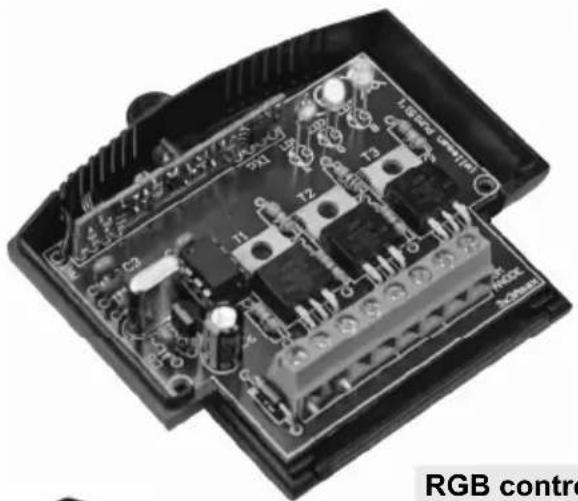
VM151

RGB controller with RF remote 3
Thank you for purchasing this module. Please read the instructions carefully to ensure correct and safe use of this device.
SPECIFICATIONS & FEATURES
Ideal for use with flexible LED light lights strips, ex. RGB Led. (ordernr. LDB1-HS3027AC)
Features:
suited for both incandescent bulbs and LEDs
l hard transition effects: running light, Strobo, Colour loops, etc...
l smooth fade effects: colour change, flame effect, random colours, slow off etc...
wide-range effect speed adjust
memory for last selected effect & speed
5 user-editable colour tables
Hi power MOSFET outputs
☑ addressable, control up to 7 units independently
optional: 2-CHANNEL RF REMOTE CONTROL 'VM130T'
Velleman hereby certifies that the device VM151 meets the essential requirements and all other relevant stipulations of directive 1999/5/EG and 1995/5/EC.
For the complete conformity declaration check out: http://www.VELLEMAN.be/downloads/doc/ce_vm151.pdf
Specifications:
256 intensity levels/ch.
- outputs: 12V/3A
LED PWM freq: ±300Hz
power supply: 12V/9A max
TX/RX:433MHz operation
- dimensions: ± 80x70x23mm / 3.15 x 2.75 x 0.9"
WARRANTY
This product is guaranteed against defects in components and construction from the moment it is purchased and for a period of TWO YEAR starting from the date of sale. This guarantee is only valid if the unit is submitted together with the original purchase invoice. VELLEMAN components Ltd limits its responsibility to the reparation of defects or, as VELLEMAN components Ltd deems necessary, to the replacement or reparation of defective components. Costs and risks connected to the transport, removal or placement of the product, or any other costs directly or indirectly connected to the repair, will not be reimbursed by VELLEMAN components Ltd. VELLEMAN components Ltd will not be held responsible for any damages caused by the malfunctioning of a unit.
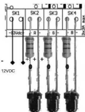
CONNECTION
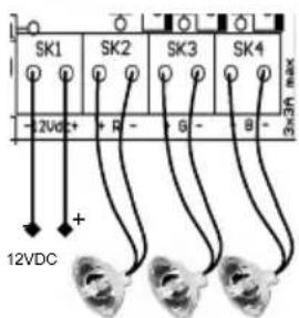
Incandescent lightbulb or halogen lightbulb:
connect the lightbulb to the output R, G or B.

Polarity is not important. 3A /channel max (36W@12V).
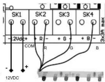
LED-strip with common anode (+):
Connect the common anode to the (+) of the 12VDC
power supply.
Connect the cathode (-) of each colour to the (-) of
R,G or B on the VM151.

Max. current consumption is 3A/channel.
LED

LEDs require a series resistor
Determine led voltage drop (Check manufacturer datasheet).
Rule of thumb: red: 1.7V, green: 2V, blue: 3..4V).
Next, check required LED current.
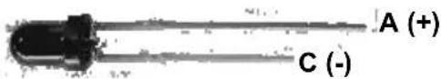
Example: Red LED, 1.7V drop, required current: 20mA
Resistor calculation: (12V-1.7V) / 0.020 = 515 ohm (choose nearest value, e.g. 560 ohm)
Resistor power rating calculation: (12V-1.7V) x (12V-1.7V) / 560 = 0.19W (choose a 0.25W resistor)
TRANSMITTER INSTRUCTIONS
The transmitter comes with a factory set default code.
Open the enclosure :

open
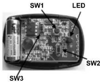
Changing the code :
- Hold SW1 (left button).
- Briefly press the 'program'-button (SW3) 3 times. The LED will flash 3 times.
- Release SW1.
- Your unique 32-bit code has been generated and stored.
Return to the default code :
- Hold SW1 (left button).
- Hold the 'program'-button (SW3). After +/- 10s the led will flash 5 times.
- Release both buttons.
- Your code has been erased.
USE
1) Using the RGB controller with the supplied RF remote control:
Left button:
Change effect (push until effect changes. Leds blank between each effect)
| Effect # | Effect description | Adjustable speed |
| 0 | Static red | x |
| 1 | Static green | x |
| 2 | Static blue | x |
| 3 | Static yellow | x |
| 4 | Static cyan | x |
| 5 | Static magenta | x |
| 6 | Static white | x |
| 7 | Hard transition red-green-blue-yellow-cyan-magenta | ✓ |
| 8 | Fade red ⇒ green ⇒ blue ⇒ red | ✓ |
| 9 | Running light red ⇒ green ⇒ blue | ✓ |
| 10 | Flame effect (3 independent flames) | ✓ |
| 11 | Hard transition between all 40 colours stored in mem. 1..5 | ✓ |
| 12 | Fade between 8 colours stored in memory 1 | ✓ |
| 13 | Fade between 8 colours stored in memory 2 | ✓ |
| 14 | Fade between 8 colours stored in memory 3 | ✓ |
| 15 | Fade between 8 colours stored in memory 4 | ✓ |
| 16 | Fade between 8 colours stored in memory 5 | ✓ |
| 17 | Random colour fade | ✓ |
Right button: effect speed change
Press and hold button until leds blank. Each press reduces speed. 8 speed settings are available.
When minimum speed is reached, the unit will jump to max. speed at the next press
To turn off:
Press and hold both buttons until display blanks. (A brief flash will confirm the action)
(Current effect and current speed will be stored in memory.
At next power-up, unit will resume)
To turn back on:
Press and hold any key until outputs are turned on again.
To make the unit respond to a transmitter:
Same procedure as turn-off. New transmitter will be stored in memory.
Unit will no longer respond to previous transmitter.
To make the unit respond to more than one transmitter:
Reset all transmitters to default code.
Make unit respond to this transmitter. All other transmitters that are set to default code will be able to control the unit.
2) Using the RGB controller with the optional USB to RF remote control transmitter;
By means of the Velleman K8074 USB to RF remote control transmitter, you can control the RGB controller from a PC, either by using the demo software or by writing custom software that suits your application.
By means of a PC you can:
Select any effect
Set an effect speed
Edit the colour memory of the RGB controller
Compose any colour 'on-the-fly'
Address up to 7 units, to create endless possibilities
Demo software screenshot:

Getting started with the demo software:
The demo software illustrates all possible functions of the VM151 RGB Controller. You can either use the demo software or you can write your own software. It is very easy to write your own software. COM-port parameters are 2400,N,8,1.
Start the demo software and place the mouse pointer on a button. A tool tip will reveal the string you need to send to the K8074 in order to make it perform that function. To ensure proper reception of each command, we recommend to send the command string 10 times in a row. Of course, you can also analyse the source code of the demo software.
Download: www.velleman.eu
Attention: 3A/canal max (36W@12V).
1) Using the RGB controller with the supplied RF remote control:
All repairs should be executed by qualified technicians.
Avoid the installation of the module in locations with standing or running water or excessive humidity. Indoor use only!
■ Handle the module gently and carefully. Dropping it can damage the circuit board.
Never exceed the protection limit values indicated in the specifications.
As safety requirement vary, please check with your local authorities.
Facilitate the operation of the device by familiarising yourself with its adjustments and indications.
Velleman modules are not suitable for use or as part of life support systems, or systems that might create hazardous situations of kind.
SAFETY INSTRUCTIONS
This symbol on this unit or the package, indicates that dispose. Do not dispose the unit as in assorted municipal waste: it sho
a unit should be returned to your distributor or to a local recycling service. Respect the local environmental rules. If any doubt contact your local authorities about waste disposal rules.
RGB Controller with RF remote
Belgium [Head office] Velleman Components +32(0)9 384 36 11
France Velleman Electronique +33(0)3 20 15 86 15
Netherlands Velleman Components +31(0)76 514 7563
USA Velleman Inc.
Spain Velleman Components +32(0)9 384 36 11

+1(817)284-7785

velleman
M O D U L E S


Modifications and typographical errors reserved - © Velleman Components nv - HVM151G - 2008 - ED1 (rev.2)


- RGB CONTROLLER WITH RF REMOTE
- SPECIFICATIONS & FEATURES
- Features:
- Specifications:
- WARRANTY
- CONNECTION
- Incandescent lightbulb or halogen lightbulb:
- LED-strip with common anode (+):
- LED
- TRANSMITTER INSTRUCTIONS
- Open the enclosure :
- Changing the code :
- Return to the default code :
- USE
- 1) Using the RGB controller with the supplied RF remote control:
- Left button:
- Right button: effect speed change
- To turn off:
- To turn back on:
- To make the unit respond to a transmitter:
- To make the unit respond to more than one transmitter:
- 2) Using the RGB controller with the optional USB to RF remote control transmitter;
- By means of a PC you can:
- Demo software screenshot:
- Getting started with the demo software:
Brand : VELLEMAN
Model : VM151
Category : Remote control