TC2CTL1 - Projector Accessory VISION - Free user manual and instructions
Find the device manual for free TC2CTL1 VISION in PDF.
| Product type | Infrared control module (projector accessory) |
| Brand | Vision |
| Model | TC2CTL1 |
| Dimensions (L × W × H) | 71 × 42 × 40 mm |
| Weight | 63 g |
| Color | White |
| Power supply | 2 AAA batteries (1.5 V) |
| Recommended battery type | Alkaline or lithium for heavy use |
| Battery life | Approximately 12 months depending on usage |
| IR receiver | Yes |
| IR emitter (IR Blaster) | Yes, with 10 m cable |
| Number of interchangeable key sets | 9 key sets provided |
| Main functions | On/Off control, source selection (PC, video), volume, IR code learning |
| Control modes | Single or double for central keys (selector at rear) |
| Installation | To be recessed into a Techconnect faceplate (not supplied) |
| Compliance | RoHS, WEEE (EU directives) |
| Warranty | 2 years (valid for original purchaser) |
| Package contents | 1 control module, 1 IR Blaster with cable, 9 key sets, 2 AAA batteries, 1 rear housing, 1 chassis |
| Maintenance | Clean with a dry cloth; avoid moisture and heat sources |
| Safety | Do not open the device; do not expose to rain or humidity |
| Compatibility | Data projectors, LCD and Plasma screens (not guaranteed for all models) |
Frequently Asked Questions - TC2CTL1 VISION
User questions about TC2CTL1 VISION
0 question about this device. Answer the ones you know or ask your own.
Ask a new question about this device
Download the instructions for your Projector Accessory in PDF format for free! Find your manual TC2CTL1 - VISION and take your electronic device back in hand. On this page are published all the documents necessary for the use of your device. TC2CTL1 by VISION.
USER MANUAL TC2CTL1 VISION
Congratulations on your choice of the Vision Techconnect IR Control Module. In order to obtain the best performance please be sure to read this owner's manual and use your product only in accordance with the instructions. An electronic version of this manual and further information can be found on www.visionaudiovisual.com
CONFORMITY
The product described in this owners manual is in compliance with RoHS (EU directive 2002/95/EC), and WEEE (EU directive 2002/96/EC) standards. Certificates including SGS reports are available on request.
This product should be returned to the place of purchase at the end of its useful life for recycling.
WEE/ABQ047SY
WARNING

CAUTION
RISK OF ELECTRIC SHOCK DO NOT OPEN

CAUTION: TO REDUCE THE RISK OF ELECTRIC SHOCK, DO NOT REMOVE COVER (OR BACK). NO USERSERVICEABLE PARTS INSIDE. REFER SERVICING TO QUALIFIED SERVICE PERSONNEL.
The lightning flash with arrowhead symbol, within an equilateral triangle, is intended to alert the user to the presence of uninsulated "dangerous voltage" within the product's enclosure that may be of sufficient magnitude to constitute a risk of electric shock to persons.

The exclamation point within an equilateral triangle is intended to alert the user to the presence of important operating and maintenance (servicing) instructions in the literature accompanying the appliance.
WARNING: TO REDUCE THE RISK OF FIRE OR ELECTRIC SHOCK, DO NOT EXPOSE THIS APPLIANCE TO RAIN OR MOISTURE.
PLACE OF INSTALLATION
Avoid installing your unit under the following conditions:
- Moist or humid places
- Places exposed to direct sunlight or close to heating equipment
- Extremely cold locations
- Places subject to excessive vibration or dust
Poorly ventilated places
BATTERY LIFE
This product uses 2 × AAA batteries. You should get around 12 months use out of your batteries depending on usage. If your usage is heavy we recommend Lithium batteries to extend the life. The batteries are housed in a sealed compartment and should remain dry. If the product is installed in a humid climate you should check the batteries every six months to make sure they do not get damp or rust.
LIMITATIONS OF PRODUCT
This product has been tested and works with a very wide variety of data projectors, LCD screens, and Plasma screens. Some display products use different IR code standards, so we do not guarantee this control module will control all available display products. Many motorized projection screens use different codes and therefore cannot be controlled by this product.
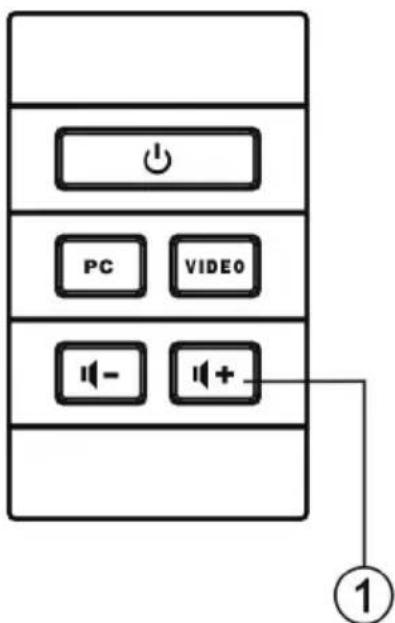
MODULAR BUTTONS INCLUDED
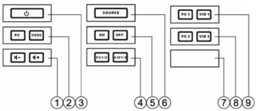
- VOLUME Button
- PC/VIDEO Button
- POWER Button
- PC1/2/
VID1/2 Button
- ON/OFF Button
- SOURCE panel
- BLANK panel
- PC2 / VID2 Button
- PC1 / VID1 Button
PACKAGING
Save all packing material. It is essential for shipping in the event the unit ever needs repair.
IF ORIGINAL PACKAGING IS NOT USED TO RETURN THE UNIT TO THE SERVICE CENTRE, DAMAGE IN TRANSIT WILL NOT BE COVERED BY WARRANTY.
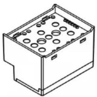
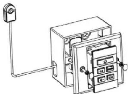
FRONT AND REAR CONTROL PANELS
- Function Button
- IR Blaster Output
- IR Receiver
- Learn Mode LED (red)
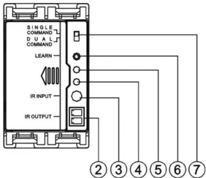
- Learn Confirmation LED (green)
- Learn Mode Button
- Single/Dual Code selector (only applies to middle buttons)
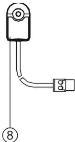
- IR Blaster (also known as emitter)
OPERATING INSTRUCTIONS
The Techconnect IR Control is designed to replicate the function of your projector or flat-panel IR remote control. By using the Techconnect Control you will present users with a standardized way of controlling their equipment, and the original remote control can be safely locked away.
①
(2)
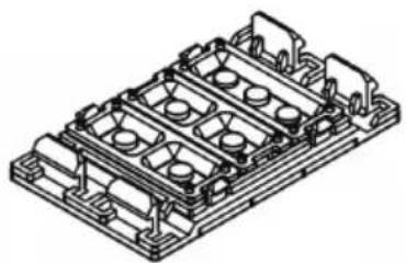
- SEPARATE FRONT PANEL FROM REAR Gently separate the front panel from the rear chassis. The front panel is held on by clips on each side towards the front.
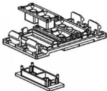
- LOAD BUTTONS The front panel comes pre-loaded with a common configuration of buttons. You will need to change buttons to suit the projector you are controlling. For example, if the remote control you are learning from has separate on and off buttons, you will need to use that button set in the Techconnect Control. Likewise for the source selection buttons some projector remotes use a single toggle button to select inputs, while other remote controls use more buttons. If your projector remote control has four separate buttons for each input (e.g. PC1, PC2, Video, S-Video), then you should install the "PC1/2 / VID1/2" button set in the middle of the front panel. Re-attach the front panel to the rear chassis.
- SELECT DUAL OR SINGLE COMMAND FOR MIDDLE BUTTONS The "Single/Dual Command" switch on the rear selects whether you want the middle buttons to learn one code each, or two discreet codes each. If your projector remote control has four separate buttons for each input, then you should set this to "Dual". For all other circumstances you only need the middle buttons to learn one code each, so it should be set to "Single".
- LEARN CODES FROM ORIGINAL REMOTE CONTROL To program each button follow these simple steps. In this example we will program the power button. Before you start ensure that the batteries are installed by pressing any one of the buttons on the front panel - you will hear a "beep".
a) Press the "Learn" button on the rear. The red LED will light up and stay lit.
b) Press the button on the front panel you want to assign the code to - in this example the power button.
c) Point the original remote control at the "IR Input" receiver on the back of the module. Press and hold the power button on the remote control until the green confirmation LED lights briefly on the rear of the module. It will normally take 1-2 seconds.
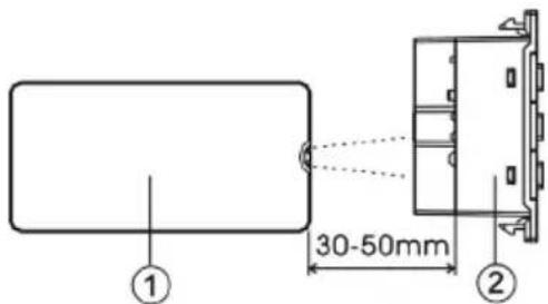
- Original Remote Control
- IR Input receiver
The Techconnect Control has now assigned that code to the button and is no longer in learn mode. Repeat all steps including step (a) to program the other buttons. Note: If you are programming one of the middle buttons in dual command mode it will remain in learn mode after you have taught it the first code. You should now press the second command on the original remote control. The second code will be assigned to the same middle button and the module will revert out of learn mode.
Keep the remote control 90 degrees to the receiver as shown above. The optimum learning distance is 30 - 50mm .
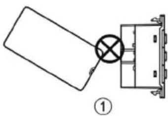

- Incorrect angle
-
Too close
-
INSTALL CONTROL MODULE INTO TECHCONNECT FACEPLATE After you've taught the Control Module the IR codes, install the module into the Techconnect faceplate, plug in the IR Blaster cable (included) and route it to the projector.
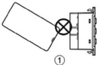
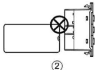
- ATTACH THE IR BLASTER TO THE PROJECTOR A powerful IR emitter is included with the Techconnect Control, attached to a 10m cable. This cable can be shortened or lengthened easily at the Phoenix connector end which plugs into the Control Module. The IR emitter should be positioned over or near the IR receiver on the projector as shown below. Option (1) is most effective as the IR signal can be weakened by direct sunlight or fluorescent lights.
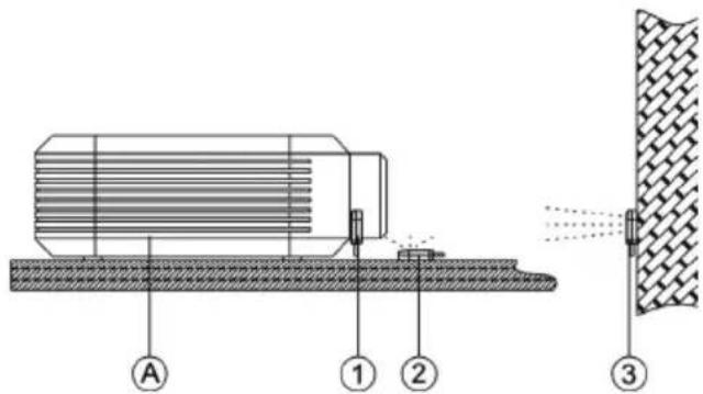
A. Projector
- Stuck on the IR receiver built in to the projector
- Sitting near the IR receiver
- Attached to a wall directly facing the IR receiver
SPECIFICATIONS
- Dimensions: 71 × 42 × 40 mm
Weight: 63 grams
Colour:White
Note: Because we are committed to improving our products, the details above may change without prior warning.
ACCESSIONS INCLUDED
9 × Interchangeable button sets
1 x Single-Gang Techconnect Backbox
1 x Single-Gang Techconnect Surround
1 x IR Blaster with 10m cable
2 x AAA Batteries
TROUBLESHOOTING
If your system is not operating properly, please refer to the following information. If the problem persists, disconnect from power and contact your AV reseller immediately.
| Problem Correction | |
| No sound when front buttons pressed | Replace the batteries. |
| Module fails to learn the code Make sure the original remote is 30-50mm away from the receiver on the back of the module, and at 90 degrees. Make sure the original remote has fresh batteries. When teaching hold down the button on the original remote for longer until the green LED lights on the Module. | |
| Module learns code and makes sound but doesn’t control the projector | Re-program the buttons. Re-position the IR blaster. Check IR blaster cable to make sure it hasn’t been damaged during installation. |
WARRANTY
This product comes with a 2-year return to base warranty, effective from the date of purchase. This warranty applies only to the original purchaser and is not transferable. For the avoidance of doubt, this will be taken from the information held by the appointed national distributor at the point of sale. If the product is DOA (dead on arrival), you have 21 days from purchase date to notify the national distributor via your AV reseller. The liability of the manufacturer and its appointed service company is limited to the cost of repair and/or replacement of the faulty unit under warranty, except for death or injury (EU85/374/EEC). This warranty protects you against the following:
- Failure of any components.
- Damage when the product is first removed from its packaging if reported within 24 hours of purchase.
If you find you do have a problem with this product, you should contact the AV reseller you purchased this product from. The original purchaser is responsible for shipment of the product to the manufacturer's appointed service centre for repair.
We will endeavour to return repaired units within 5 working days, however this may not always be possible, in which case it will be returned as soon as practicably possible. In line with our WEEE commitments, the manufacturer endeavours to replace the faulty parts of the product rather than replacing the whole unit. This warranty does not protect this product against faults caused by abuse, misuse, incorrect installation, unstable or faulty power input, which might be caused by ignoring the guidelines set out in this manual.
MANUEL DE L'UTILISATEUR DU MODULE DE COMMANDE IR TECHCONNECT
The Techconnect Control has now assigned that code to the button and is no longer in learn mode. Repeat all steps including step (a) to program the other buttons. Note: If you are programming one of the middle buttons in dual command mode it will remain in learn mode after you have taught it the first code. You should now press the second command on the original remote control. The second code will be assigned to the same middle button and the module will revert out of learn mode.
Keep the remote control 90 degrees to the receiver as shown above. The optimum learning distance is 30 - 50mm .