ТМUST TILT - Projector Accessory VISION - Free user manual and instructions
Find the device manual for free ТМUST TILT VISION in PDF.
User questions about ТМUST TILT VISION
0 question about this device. Answer the ones you know or ask your own.
Ask a new question about this device
Download the instructions for your Projector Accessory in PDF format for free! Find your manual ТМUST TILT - VISION and take your electronic device back in hand. On this page are published all the documents necessary for the use of your device. ТМUST TILT by VISION.
USER MANUAL ТМUST TILT VISION
TM-UST TECHMOUNT OWNERS MANUAL
TM-UST TECHMOUNT GUIDE DE L'UTILISATEUR
TM-UST TECHMOUNT MANUAL DE USUARIO
TM-UST TECHMOUNT GEBRUIKERSHANDLEIDING
TM-UST TECHMOUNT OWNERS MANUAL
Congratulations on your choice of the Vision TM-UST TECHMOUNT. In order to obtain the best performance please be sure to read this owner's manual and use your product only in accordance with the instructions. An electronic version of this manual and further information can be found on www.visionaudiovisual.com
CONFORMITY
The product described in this owner's manual is in compliance with RoHS (EU directive 2002/95/EC), and WEEE (EU directive 2002/96/EC) standards. Certificates including SGS reports are available on request. This product should be returned to the place of purchase at the end of its useful life for recycling.


WARNINGS
During installation take care to adhere to workplace health and safety laws:
- Attach the bracket to a rated load-bearing structure.
- Do not cut or drill any parts above head height. This should all be done using the correct safety equipment at floor level.
- Avoid overstretching which might result in the ladder tipping over.
- SWL (safe working load): 7.5kg (4.5kg if using extension pole)
THE ST8 WALL FIXTURES PROVIDED ARE ONLY FOR ATTACHMENT TO APPROPRIATE SOLID WALLS – NOT HOLLOW WALLS. ALWAYS USE THE APPROPRIATE FIXTURES. VISION DOES NOT ACCEPT LIABILITY FOR DETTACHMENT FROM THE WALL EITHER BY INSTALLATION WITH INADEQUATE FIXTURES OR OVERLOADING.
PACKAGING
Save all packing material. It is essential for shipping in the event the unit ever needs repair. IF ORIGINAL PACKAGING IS NOT USED TO RETURN THE UNIT TO THE SERVICE CENTRE, DAMAGE IN TRANSIT WILL NOT BE COVERED BY WARRANTY.
CONTENTS
1 x 2-part Boom Assembly
1 x Wall Assembly
1 x Universal Spider Fitting
1 x H50 Pin-Hex key
4 x M2.5 43mm pan slot for Optoma & Acer
4 x M3 43mm screws
4 x M4 43mm screws
4 x M5 43mm screws
4 x M6 43mm screws
6 x ST8 50mm Ceiling Fixtures with rawl plugs for wall attachment
1 x 2-part Wall Plate Cover
6 x Wall Plate Inserts
1 x Boom Cover
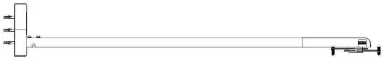
BRACKET PARTS
- Bolts
- Wall Plate
- Boom Part – section 1
- Boom Part – section 2
- Universal "Spider" Fitting
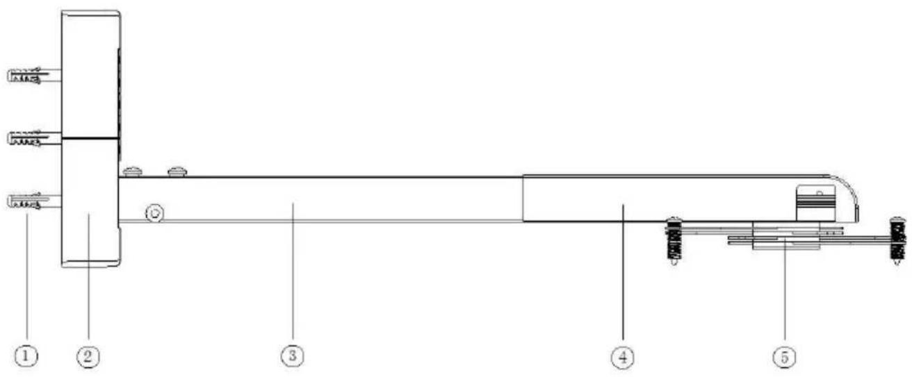
text_image
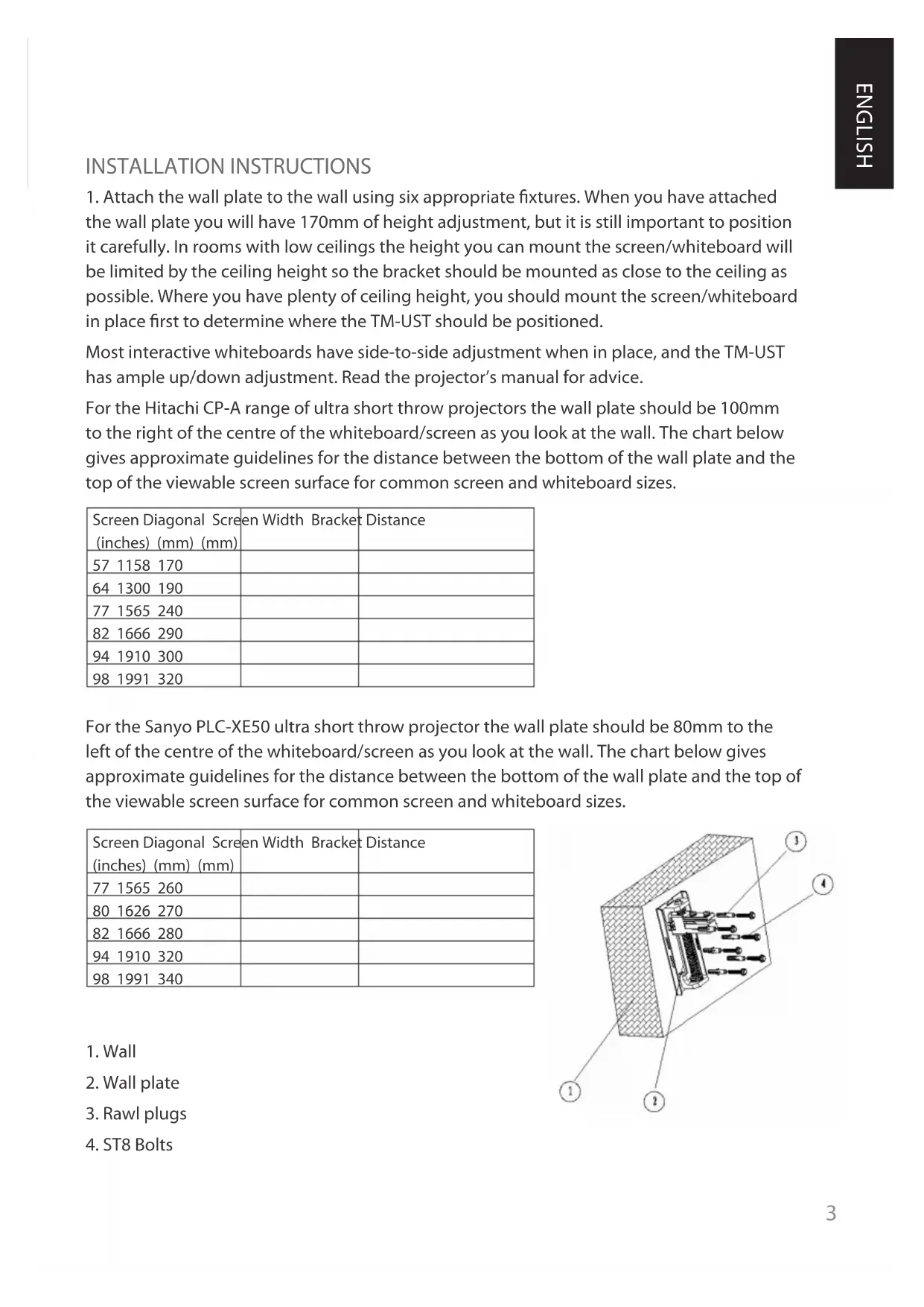
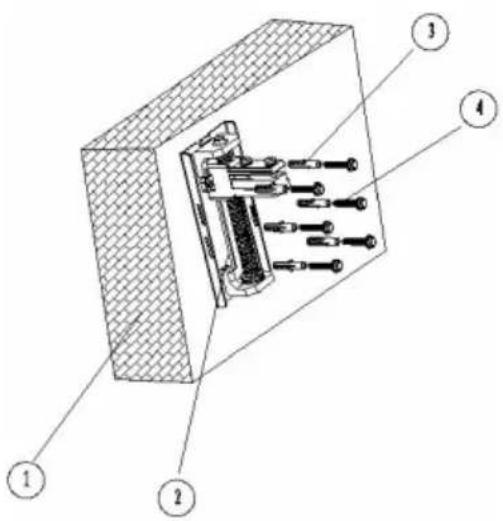
Technical diagram of a mechanical assembly with numbered components, likely a valve or actuator assembly.INSTALLATION INSTRUCTIONS
- Attach the wall plate to the wall using six appropriate fixtures. When you have attached the wall plate you will have 170mm of height adjustment, but it is still important to position it carefully. In rooms with low ceilings the height you can mount the screen/whiteboard will be limited by the ceiling height so the bracket should be mounted as close to the ceiling as possible. Where you have plenty of ceiling height, you should mount the screen/whiteboard in place first to determine where the TM-UST should be positioned.
Most interactive whiteboards have side-to-side adjustment when in place, and the TM-UST has ample up/down adjustment. Read the projector's manual for advice.
For the Hitachi CP-A range of ultra short throw projectors the wall plate should be 100mm to the right of the centre of the whiteboard/screen as you look at the wall. The chart below gives approximate guidelines for the distance between the bottom of the wall plate and the top of the viewable screen surface for common screen and whiteboard sizes.
| Screen Diagonal Screen (inches) (mm) (mm) | en Width Bracket | Distance |
| 57 1158 170 | ||
| 64 1300 190 | ||
| 77 1565 240 | ||
| 82 1666 290 | ||
| 94 1910 300 | ||
| 98 1991 320 |
For the Sanyo PLC-XE50 ultra short throw projector the wall plate should be 80mm to the left of the centre of the whiteboard/screen as you look at the wall. The chart below gives approximate guidelines for the distance between the bottom of the wall plate and the top of the viewable screen surface for common screen and whiteboard sizes.
| Screen Diagonal Screen(inches) (mm) (mm) | en Width Bracket | Distance |
| 77 1565 260 | ||
| 80 1626 270 | ||
| 82 1666 280 | ||
| 94 1910 320 | ||
| 98 1991 340 |
- Wall
- Wall plate
- Rawl plugs
- ST8 Bolts
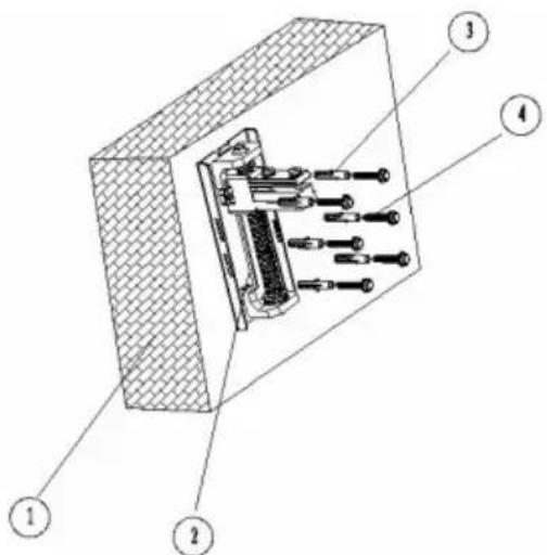
text_image
Technical diagram of a mechanical assembly with numbered components labeled 1 to 4-
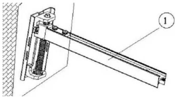
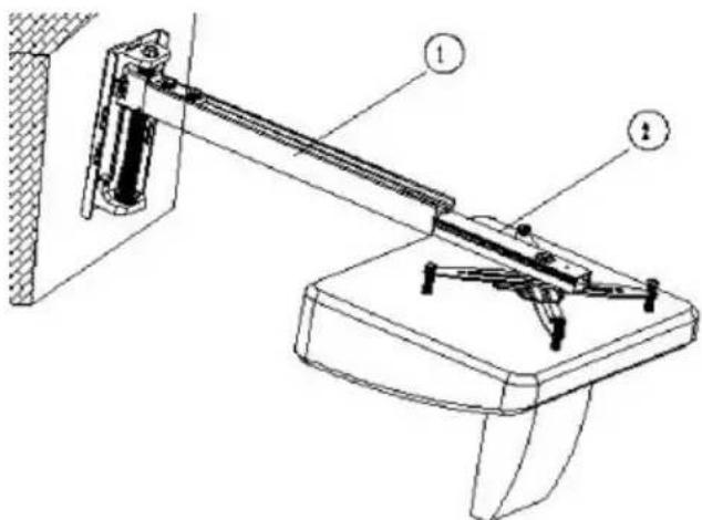
Fit section 1 of the boom to the wall plate, and fix tightly using the four pin-hex bolts included.
-
Section 1 of boom
natural_image
Technical line drawing of a mechanical clamp or bracket assembly with no visible text or symbols- Fit the universal "spider" fitting included to the projector as shown by threading the 43mm screws included through the hollow screw already in place on each "leg" of the spider. The Hitachi requires M6 screws, and the Sanyo requires M4. Other screw sizes are included to cater for other projectors.
Fit the spider to section 2 of the boom as shown:
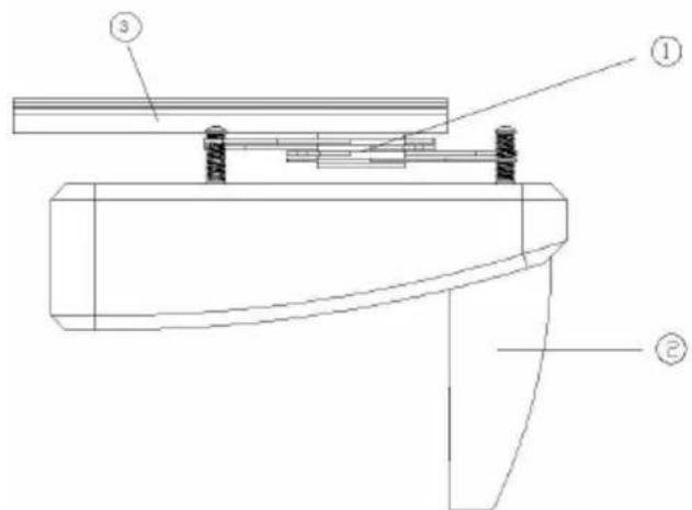
text_image
Technical diagram of a mechanical assembly with labeled components ①, ②, and ③- Universal "Spider" Fitting
- Projector
-
Section 2 of boom
-
Take the assembled parts above and slide section 2 of the boom into section 1 as shown below.
text_image
Technical diagram of a mechanical device with labeled parts, showing a lever mechanism and base structure.If the screen/whiteboard is very small (for example 57" diameter) you will need to insert section 2 projector-end first so that the projector faces away from the wall, then turn the projector 180 degrees.
- Section 1 of boom
-
Section 2 of boom
-
Plug power into the projector and turn it on. Follow these steps to setup the projector:
-
Adjust the boom length so that the projected image matches the screen WIDTH (don't worry about height yet), making sure the projector lens is exactly in the centre of the screen.
Note once you have done this adjustment for screens/whiteboards less than 77" (diameter) or 1500mm (wide), section 1 may protrude beyond the rear of the projector and may require shortening. In this case follow this process:
- Mark the excess length of section 1
- Remove the projector and section 2 assembly from section 1
- Cut section 1 shorter with a hacksaw at the projector end.
Lock section 2 into position with the locking pin-hex bolts on the top surface of section 1.
-
Use a spirit level and the hollow adjustment screws in the end of each spider leg to make sure the projector is level.
-
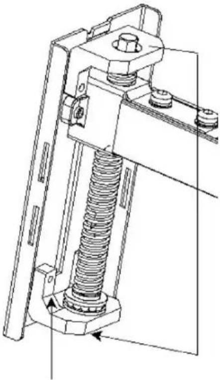
Turn the wall plate adjustment bolt (shown below) to move the boom up or down as required. If the screen is not perfectly flat and perpendicular to the projector lens the projected image may not perfectly fit the screen. In which case make small adjustments to the spider adjustment screws if necessary. Large adjustments will result in a poor image.
natural_image
Technical line drawing of a mechanical assembly with a spring and bolted joint (no text or symbols)- Up/Down adjustment bolt (accessible from the top or bottom of the wall plate)
Once all adjustments are made, insert the pin-hex bolts that lock the boom in place to the wall plate.
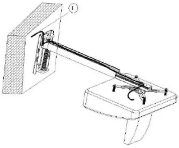
- Route the power and inputs cables as shown and clip the covers into place:
natural_image
Technical line drawing of a mechanical device with labeled components (no text or symbols present)- Cable routing at top and bottom of wall plate
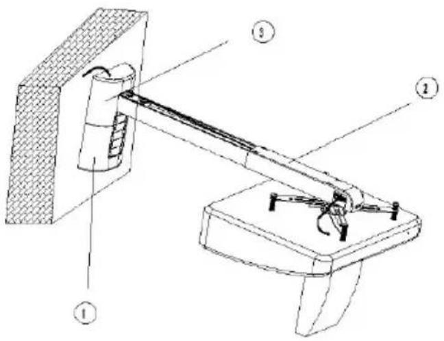
text_image
Technical diagram of a mechanical device with numbered components, likely a robotic or mechanical assembly.-
Wall plate cover
-
Boom cover
-
Wall plate inserts (use to cover the boom adjustment range hole on the wall cover)
ALTERNATIVE EXTENSION POLE FITTING
The TM-UST can be extended to up to 1.5m for short throw projectors. This is achieved by fitting the extension pole to section 1, then fitting section 2 to the extension pole. To cut excess length off the extension pole follow this process:
Turn the projector on. Slide section 2 up and down the extension a. pole into position so that the image matches the width of the screen/whiteboard.
Mark the excess length of the extension poleb.
Turn the projector off. Remove the projector and section 2 assembly from c. the extension pole.
Cut the extension pole shorter with a hacksaw at the projector end.d.
Replace the projector and section 2 assembly and finish installation.
natural_image
Pure technical line drawing of a mechanical assembly without any text, numbers, or symbolsWARNING: THE SAFE WORKING LOAD LIMIT WITH THE EXTENSION POLE IS 4.5KG. DO NOT FIT THE EXTENSION POLE TO SECTION 1 IF SECTION 1 HAS BEEN SHORTENED.
WARRANTY
This product comes with a 2-year return to base warranty, effective from the date of purchase. This warranty applies only to the original purchaser and is not transferable. For the avoidance of doubt, this will be taken from the information held by the appointed national distributor at the point of sale. The liability of the manufacturer and its appointed service company is limited to the cost of repair and or replacement of the faulty unit under warranty, except for death or injury (EU85/374/EEC). This warranty protects you against the following:
- Faulty wields resulting in the product not safely performing its task within the recommended SWL (safe working load).
- Poor finishing resulting in the product not being able to be assembled.
- External corrosion if identified within 24 hours of purchase.
If you find you do have a problem with this product, you should contact the AV reseller you purchased this product from. The original purchaser is responsible for shipment of the product to the manufacturer's appointed service centre for repair.
We will endeavour to return repaired units within 5 working days, however this may not always be possible in which case it will be returned as soon as practically possible. This warranty does not protect this product against faults caused by abuse, misuse, or incorrect installation which might be caused by ignoring the guidelines set out in this manual.
If failure is not covered by this warranty, the owner will be given the option to pay for labour and parts to repair the unit at the service company's standard rate.
TM-UST TECHMOUNT GUIDE DE L'UTILISATEUR
text_image
Technical diagram of a mechanical assembly with numbered components and labeled partsINSTRUCTIONS D'INSTALLATION
- Mur
- Plaque murale
- Crochets
- Boulons ST8
text_image
Technical diagram of a mechanical assembly with numbered components labeled 1 to 4text_image
support mobile ①text_image
Technical diagram of a mechanical assembly with labeled components ①, ②, and ③text_image
Technical diagram of a mechanical device with labeled parts, showing a lever and base assembly.natural_image
Technical line drawing of a mechanical assembly with a spring-loaded component (no text or symbols)natural_image
Technical line drawing of a mechanical device with labeled components (no text or symbols present)text_image
Technical diagram of a mechanical device with numbered components, likely a lifting or mounting mechanism.natural_image
Pure technical line drawing of a mechanical assembly without any text, numbers, or symbolsAVERTISSEMENT : LA CHARGE MAXIMALE AUTORISÉE DE LA BARRE D'EXTENSION EST DE 4.5KG. NE PAS INSÉRER LA BARRE D'EXTENSION DANS LA PARTIE 1 SI CETTE DERNIÈRE A ÉTÉ RACCOURCIE.
GARANTIE
text_image
Technical diagram of a mechanical assembly with numbered components and labeled partstext_image
Technical diagram of a mechanical assembly with numbered components labeled 1, 2, 3, and 4.natural_image
Technical line drawing of a mechanical clamp or bracket assembly with no visible text or symbolstext_image
Technical diagram of a mechanical assembly with labeled components ①, ②, and ③text_image
Technical diagram of a mechanical device with labeled parts, showing a lever mechanism and base structure.natural_image
Technical line drawing of a mechanical assembly with a spring and bolted joint (no text or symbols)natural_image
Technical line drawing of a mechanical lever system mounted on a base (no text or symbols present)text_image
Technical diagram of a mechanical device with numbered components, likely a lifting or mounting mechanism.natural_image
Pure technical line drawing of a mechanical assembly without any text, numbers, or symbolstext_image
Technical schematic diagram of a mechanical assembly with numbered components labeled 1 through 5.INSTALLATIE-INSTRUCTIES
text_image
Technical diagram of a mechanical assembly with numbered components labeled 1 to 4natural_image
Technical line drawing of a mechanical assembly with spring and rod components (no text or symbols)text_image
Technical diagram of a mechanical assembly with labeled components ①, ②, and ③text_image
Technical diagram of a mechanical device with labeled parts, showing a lever mechanism and base structure.natural_image
Technical line drawing of a mechanical assembly with a spring-loaded component (no text or symbols)natural_image
Technical line drawing of a mechanical lever system mounted on a base (no text or symbols present)text_image
Technical diagram of a mechanical device with labeled components, showing a lever mechanism and structural parts.natural_image
Pure technical line drawing of a mechanical assembly without any text, numbers, or symbolsWAARSCHUWING: DE VEILIGE WERKLADING VAN HET VERLENGSTUK IS 4.5KG. BEVESTIG HET VERLENGSTUK NIET AAN SECTIE 1 ALS SECTIE 1 IS INGEKORT.
GARANTIE
text_image
Technical diagram of a mechanical assembly with numbered components and labeled partsMONTAGEANLEITUNG
text_image
Technical diagram of a mechanical assembly with numbered components labeled 1 to 4natural_image
Technical line drawing of a mechanical clamp or bracket assembly (no text or symbols)text_image
Technical diagram of a mechanical assembly with labeled components ①, ②, and ③text_image
Technical diagram of a mechanical device with labeled parts, showing a lever and base structure.natural_image
Technical line drawing of a mechanical assembly with a spring and bolted joint (no text or symbols)natural_image
Technical line drawing of a mechanical device with labeled components (no text or symbols present)text_image
Technical diagram of a mechanical device with numbered components, likely for assembly or maintenance instructions.natural_image
Pure technical line drawing of a mechanical assembly without any text, numbers, or symbolstext_image
Technical diagram of a mechanical assembly with numbered components and labeled partstext_image
Technical diagram of a mechanical assembly with numbered components labeled 1 to 4natural_image
Technical line drawing of a mechanical clamp or bracket assembly (no text or symbols)text_image
Technical diagram of a mechanical assembly with labeled components ①, ②, and ③text_image
Technical diagram of a mechanical device with labeled parts, showing a lever and base assembly.natural_image
Technical line drawing of a mechanical assembly with a spring and bolted joint (no text or symbols)natural_image
Technical line drawing of a mechanical device with labeled components (no text or symbols present)text_image
Technical diagram of a mechanical device with labeled components, showing a lever mechanism and base structure.natural_image
Pure technical line drawing of a mechanical assembly without any text, numbers, or symbolstext_image
Technical diagram of a mechanical assembly with numbered components, likely a valve or actuator assembly.INSTALACJA
text_image
Technical diagram of a mechanical assembly with numbered components labeled 1, 2, 3, and 4.natural_image
Technical line drawing of a mechanical assembly with spring and frame components (no text or symbols)text_image
Technical diagram of a mechanical assembly with labeled components ①, ②, and ③text_image
Technical diagram of a mechanical device with labeled components, showing a lever and base assembly.natural_image
Technical line drawing of a mechanical assembly with a spring and bolted joint (no text or symbols)natural_image
Technical line drawing of a mechanical device with labeled components (no text or symbols present)text_image
Technical diagram of a mechanical device with labeled components, showing a lever mechanism and support structure.natural_image
Technical line drawing of a mechanical assembly with no visible text or symbolsOSTRZEŻENIE: W PRZYPADKU ZASTOSOWANIA BELKI PRZEDŁUŻAJĄCEJ, MAKSYMALNE DOPUSZCZALNE OBCIĄŻENIE ROBOCZE UCHWYTU WYNOSI 4,5 KG. NIE WOLNO ZAKŁADAĆ BELKI PRZEDŁUŻAJĄCEJ, JEŻELI SKRÓCONO SEGMENT 1 WYSIĘGNIKA.