Powerlan 6420 Mini - Powerline Adapter TOPCOM - Free user manual and instructions
Find the device manual for free Powerlan 6420 Mini TOPCOM in PDF.

User questions about Powerlan 6420 Mini TOPCOM
0 question about this device. Answer the ones you know or ask your own.
Ask a new question about this device
Download the instructions for your Powerline Adapter in PDF format for free! Find your manual Powerlan 6420 Mini - TOPCOM and take your electronic device back in hand. On this page are published all the documents necessary for the use of your device. Powerlan 6420 Mini by TOPCOM.
USER MANUAL Powerlan 6420 Mini TOPCOM
natural_image
Two white industrial power strip devices, one with ventilation grilles and the other a 200 Mbps indicator (no visible text or symbols on the devices themselves)Quick installation guide / Snelstartgids
This product is in compliance with the essential requirements and other relevant provisions of the R&TTE directive. This is confirmed by the CE-mark.
The Declaration of conformity can be found on:
http://www.topcom.net/cedeclarations.asp
NL
PowerLan 6420 mini plugs can be used to establish a network connection between your modem, PC, set-top Box, games console, etc.
By default, the PowerLan 6420 mini plugs are not connected. To connect them, follow the procedure given in Chapter 5.
Limitations
Ideally, the maximum cable length between two Powerline devices should be no more than 200 metres.
The connection quality will be impaired by:
– poor-quality electrical cabling.
- fuses.
– lightning/power surge protectors.
– multiphase voltage: some houses have three-phase electricity. The quality of the Powerline connection will be dramatically impaired if the devices are connected to different phases. In some cases, there will be no communication at all.
- Some electrical equipment, such as microwave ovens, vacuum cleaners, and old laptop/mobile phone chargers, will generate background noise on the mains network during operation.
2 Safety instructions
For your own safety, make sure you read and follow all warning notices and instructions.
- Do not open the device. Opening or removing the device cover can expose you to dangerous high-voltage points or other risks. The device can only be serviced by qualified service staff. Please contact your vendor for further information.
- Do not use the device during a thunderstorm. There may be a risk of electric shocks due to lightning.
- Do not expose the device to dust or corrosive liquids.
- Do not use this product near water sources.
- Make sure the cables are connected to the right port.
- Do not obstruct the vents on the device.
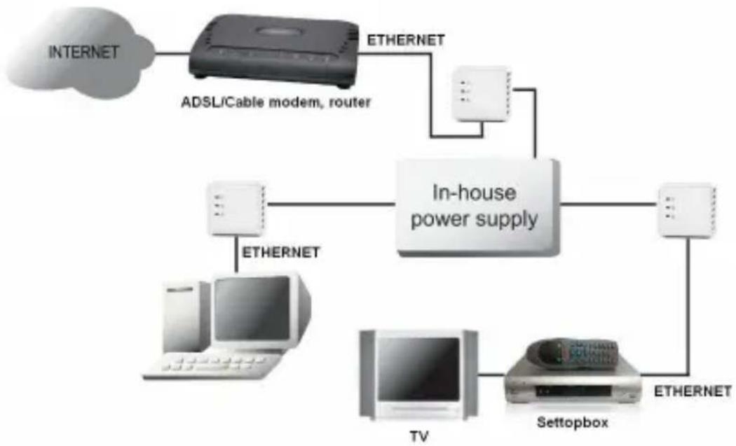
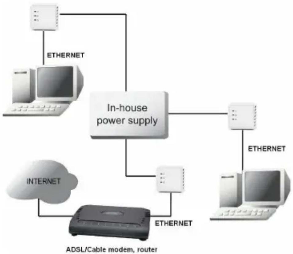
3 Typical applications
flowchart
graph TD
    A["INTERNET"] --> B["ADSL/Cable modem, router"]
    B --> C["ETHERNET"]
    C --> D["In-house power supply"]
    D --> E["TV"]
    D --> F["Settopbox"]
    D --> G["ETHERNET"]
    E --> H["OTHERNET"]
    F --> I["OTHERNET"]
flowchart
graph TD
    A["In-house power supply"] --> B["Computer"]
    A --> C["Computer"]
    A --> D["Computer"]
    A --> E["ADSL/Cable modem, router"]
    F["Internet"] --> G["Adsidized device"]
    G --> H["Ethernet"]
    I["Ethernet"] --> A
    J["Ethernet"] --> A
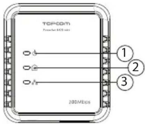
4 Description
① Power supply LED

- On: normal operation
- Flashing (0.5 seconds on/0.5 seconds off): in connection mode.
- Slow flashing (4 seconds on/11 seconds off): in stand-by mode (energy saving mode)
② Powerline LED

Shows the quality of the connection with other Powerline plugs.
– Green: excellent quality.
- Orange: good quality.
- Red: poor quality. The LED flashes during data transfer.
③ Ethernet LED:

- On: successful connection with another device through an Ethernet cable. The LED flashes when data is being transferred.
④ Ethernet connection (RJ45):
For connection to an external device through an Ethernet cable.
⑤ Full reset button:
- Push in the reset button, with a paper clip for example, for 3 seconds to reset the Powerline. Following reset, the standard password "HomePlugAV" will be loaded.
text_image
TOPCOM Powercam 6420 mini 1 2 3 200Mbps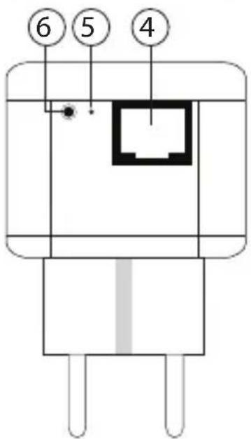
text_image
⑥ ⑤ ④⑥ Reset/simple connect button
- Push down for two seconds to start the connection sequence.
- Push down for 12 seconds to restore the factory settings. The network password will be erased.

The Powerline plug switches to stand-by mode (energy saving function) when it is not connected to a device through an Ethernet cable for 15 minutes.
5 Connecting the PowerLan 6420 mini plugs
By default, the PowerLan 6420 mini plugs are not connected. To connect them with each other, follow the procedure set out below.
- Plug all the Powerlines into the power socket.

The easiest way is to plug them in next to each other in the same place. Once they have been successfully connected, you can put them in the desired location.
-
Push down the (reset/simple connect) key on the first Powerline plug for two seconds. The power-supply LED will flash slowly (0.5 seconds on/0.5 seconds off).
-
Within two minutes, push down the key on the second plug. The connection sequence starts.
A random password will be exchanged between the Powerlines.
Once the connection is complete, restart both plugs and the Powerline LEDs on both plugs will light up.

Push down the reset/simple connect key for at least 12 seconds to restore the PowerLan 6420 mini factory settings. When the factory settings are restored, the PowerLan 6420 mini plug will need to be reconnected!
6 Adding an additional PowerLan 6420 mini
A Powerline network can be created with up to a maximum of eight Powerlines. If you already have two Powerlines in operation, you can add a maximum of six.
To add a Powerline, follow the procedure set out below.
-
Plug the extra Powerline into the power socket.
-
Push down for two seconds on the key on one of the Powerline plugs that is already in operation.
The on/off light will flash slowly (0.5 seconds on/0.5 seconds off).
- Within two minutes, push down the key on the extra Powerline plug for two seconds.
The connection sequence starts.
Once the connection is complete, restart the plugs and the Powerline LEDs on both plugs will light up.

Before adding the new Powerline, it is recommended that the network passport for this plug be changed by pushing down the "reset/simple connect" button for 12 seconds.
A Powerline that has already been used in another network will still have the password for that network, which means that the "reset/simple connect" button mechanism will not operate.
7 PC help programme (Utility)
The Powerline plugs can also be configured using the PC software provided. For this, please read the English manual on the CD-ROM.
8 Topcom Warranty
8.1 Warranty period
The Topcom units have a 24-month warranty period. The warranty period starts on the day the new unit is purchased.
Consumables or defects causing a negligible effect on operation or value of the equipment are not covered.
The warranty has to be proven by presentation of the original or copy of the purchase receipt, on which the date of purchase and the unit-model are indicated.
8.2 Warranty exclusions
Damage or defects caused by incorrect treatment or operation and damage resulting from use of non-original parts or accessories are not covered by the warranty.
The warranty does not cover damage caused by outside factors, such as lightning, water and fire, nor any damage caused during transportation.
No warranty can be claimed if the serial number on the units has been changed, removed or rendered illegible.
Any warranty claims will be invalid if the unit has been repaired, altered or modified by the buyer.
9 Disposal of the device (environment)
natural_image
Symbol of a trash bin crossed with two crossed lines and a solid rectangle below (no text or labels)At the end of the product lifecycle, you should not throw this product into the normal household garbage but bring the product to a collection point for the recycling of electrical and electronic equipments. The symbol on the product, user guide and/or box indicate this.
Some of the product materials can be re-used if you bring them to a recycling point. By re-using some parts or raw
materials from used products you make an important contribution to the protection of the environment. Please contact your local authorities in case you need more information on the collection points in your area.
1 Inleiding
7 PC Hulpprogramma (Utility)
natural_image
Symbol of a trash bin crossed with a diagonal line, no text or labels presentnatural_image
Simple line drawing of a trash bin with crossed lines indicating no waste or prohibition (no text or symbols)natural_image
Symbol of a trash bin crossed with two crossed lines and a solid black rectangle below (no text or labels)text_image
Symbol of a trash bin crossed with a crossed-out line, indicating no waste or disposal.natural_image
Symbol of a trash bin crossed with two crossed lines, no text or labels presentnatural_image
Symbol of a trash bin crossed out by two crossed lines, with no text or labels present.text_image
Symbol of a trash bin crossed out by two crossed lines, indicating no waste or discharge.visit our website www.topcom.net