Adagio PRF0006207 - Basket ELICA - Free user manual and instructions
Find the device manual for free Adagio PRF0006207 ELICA in PDF.
Download the instructions for your Basket in PDF format for free! Find your manual Adagio PRF0006207 - ELICA and take your electronic device back in hand. On this page are published all the documents necessary for the use of your device. Adagio PRF0006207 by ELICA.
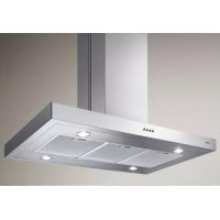
USER MANUAL Adagio PRF0006207 ELICA
EN Instruction on mounting and use
chiamare l'assistenza tecnica.13
EN - Instruction on mounting and use
Closely follow the instructions set out in this manual. All
responsibility, for any eventual inconveniences, damages or
fires caused by not complying with the instructions in this
manual, is declined.
The hood can look different to that illustrated in the
drawings in this booklet. The instructions for use,
maintenance and installation, however, remain the same.
! It is important to conserve this booklet for consultation at
any moment. In the case of sale, cession or move, make
sure it is together with the product.
! Read the instructions carefully: there is important
information about installation, use and safety.
! Do not carry out electrical or mechanical variations on the
product or on the discharge conduits.
Note: the elements marked with the symbol “(*)” are optional
accessories supplied only with some models or elements to
purchase, not supplied.
WARNING! Do not connect the appliance to the mains until
the installation is fully complete.
Before any cleaning or maintenance operation, disconnect
hood from the mains by removing the plug or disconnecting
the mains electrical supply.
Always wear work gloves for all installation and maintenance
The appliance is not intended for use by children or persons
with impaired physical, sensorial or mental faculties, or if
lacking in experience or knowledge, unless they are under
supervision or have been trained in the use of the appliance
by a person responsible for their safety.
This appliance is designed to be operated by adults, children
should be monitored to ensure that they do not play with the
This appliance is designed to be operated by adults. Children
should not be allowed to tamper with the controls or play with
Never use the hood without effectively mounted grating!
The hood must NEVER be used as a support surface unless
specifically indicated.
The premises where the appliance is installed must be
sufficiently ventilated, when the kitchen hood is used together
with other gas combustion devices or other fuels.
The ducting system for this appliance must not be connected
to any existing ventilation system which is being used for any
other purpose such as discharging exhaust fumes from
appliances burning gas or other fuels.
The flaming of foods beneath the hood itself is severely
The use of exposed flames is detrimental to the filters and
may cause a fire risk, and must therefore be avoided in all
Any frying must be done with care in order to make sure that
the oil does not overheat and ignite.
Accessible parts may become hot when used with cooking
With regards to the technical and safety measures to be
adopted for fume discharging it is important to closely follow
the regulations provided by the authorised authorities.
The hood must be regularly cleaned on both the inside and
outside (AT LEAST ONCE A MONTH).
This must be completed in accordance with the maintenance
instructions provided in this manual). Failure to follow the
instructions provided in this user guide regarding the cleaning
of the hood and filters will lead to the risk of fires.
Do not use or leave the hood without the lamp correctly
mounted due to the possible risk of electric shocks.
We will not accept any responsibility for any faults, damage or
fires caused to the appliance as a result of the non-
observance of the instructions included in this manual.
When handling the hood do not put hands within the range of
action of the pull-out suction panel (trolley)
The hood is equipped with safety switches which inhibit
operation when the front filter panel is unhooked.
With the intention of constantly improving our products, we
reserve the right to make all the changes in their technical,
functional or design characteristics, deriving from their
evolution. In case of the version with external motor, the
normal operation of the hood requires the use of a suction unit
(external motor) of the same manufacturer.
This appliance is marked according to the European directive
2002/96/EC on Waste Electrical and Electronic Equipment
(WEEE). By ensuring this product is disposed of correctly, you
will help prevent potential negative consequences for the
environment and human health, which could otherwise be
caused by inappropriate waste handling of this product.
on the product, or on the documents
accompanying the product, indicates that this appliance may
not be treated as household waste. Instead it should be taken
to the appropriate collection point for the recycling of electrical
and electronic equipment. Disposal must be carried out in
accordance with local environmental regulations for waste
The hood is designed to be used either for exhausting or filter
In this case the fumes are conveyed outside by means of a
special pipe connected with the connection ring located on top
Attention! The exhausting pipe is not supplied and must be
Diameter of the exhausting pipe must be equal to that of the
connection ring = 150mm.
In the horizontal runs the exhausting pipe must be slightly
slanted (about 10°) and directed upwards to vent the air easily
from the room to the outside.
Attention! If the hood is supplied with active charcoal filter,
then it must be removed.
One active charcoal filter is needed for this and can be
obtained from your usual retailer.
The filter removes the grease and smells from the extracted
air before sending it back into the room through the upper
Note: The recycled air in the charcoal filter is sent back to the
kitchen through a duct which conveys air on a side of the
Non-return valve locking
Attention, before connecting the flexible air outlet pipe make
sure that the non-return valves of the suction unit can freely
The models with no suction motor only operate in ducting
mode, and must be connected to an external suction device
The connecting instructions are supplied with the peripheral
When installing the product, it is recommended to keep a
minimum distance of 400mm between the worktop and any
components laid on top of the hood.
This is to let the suction panel move upwards (opening) and
downwards (closing) without any obstacles, and to facilitate
access to the hood controls on the panel.
WARNING: Put the metal box containing the electronic
components at a distance not shorter than 65 cm from the gas
hob or 65 cm from the hood suction point.
RECOMMENDATION: We recommend you to install the
metal box containing the electronic components at a distance
of at least 10 cm from the ground and sufficiently from all the
sources of heat (e.g.: side of an oven or hob).
If the instructions for installation for the gas hob specify a
greater distance, this must be adhered to.
Electrical connection
The hood must be connected to the mains supply by qualified
and trained technicians.
The mains power supply must correspond to the rating
indicated on the plate situated inside the hood. If provided with
a plug connect the hood to a socket in compliance with current
regulations and positioned in an accessible area. If it not fitted
with a plug (direct mains connection) or if the plug is not
located in an accessible area apply a double pole switch in
accordance with standards which assures the complete
disconnection of the mains under conditions relating to over-
current category III, in accordance with installation
Warning! Before re-connecting the hood circuit to the mains
supply and checking the efficient function, always check that
the mains cable is correctly assembled.
Warning! Power cable replacement must be undertaken by
the authorised service assistance centre or similar qualified
Before starting to mount the appliance, make sure that no
component is damaged, otherwise contact the dealer and stop
mounting. In addition, read all the instructions below carefully.
• Use an air outlet pipe no longer than 5 metres.
• Limit the number of curves in the duct since each curve
reduces the suction effectiveness equivalent to 1 linear
metre. (E.g.: if two 90° curves are used, the duct should
be no longer than 3 metres).
• Avoid drastic changes of direction.
• Use a duct with 150mm diameter constant for the whole
• Use a duct made of standard complying material.
• Remove the safety shim highlighted in the picture (Fig. 1-
2) at the end of the installation.
• In case of failure to observe the instructions above, the
supplier can not be held responsible for capacity or noise
problems and no warranty will be granted.
• Before making the hole, make sure that the inside of the
cabinet, near the hood housing area, does not have the
structure of the cabinet or other particulars which may
cause problems for the proper installation. Make sure
that the overall dimensions of the hood and the hob ae
compatible with the cabinet and therefore the installation
• Make a 848x100mm rectangular hole on the back of the
• In case of version with motor already mounted, remove
the screws and the suction unit to insert the hood into the
• Install the hood in the hole made, inserting it from above,
as shown (Fig. 3). In case of version with motor on
board, it is necessary to remove the suction unit before
inserting the product into the cabinet.
• Fix the hood inside the cainet using the special brackets
supplied (Fig. 4). Start mounting the brackets in the lower
part of the hood (Fig. 5a) making sure that there is a
distance of 2 mm between the lower part of the bracket
and the cabinet bottom (Fig. 5b). This distance allows
the traction of the product downwards on fixing, (Fig. 5c),
so that the stainless steel frame adheres perfectly on the
• Before inserting the screws into the cabinet, make sure
that the product is perfectly perpendicular to the worktop.
• After completing the installation and connecting the
product to the power supply, lift the hood and remove the
• In case of version with motor on board start mounting the
motor unit directing the air outlet to the chosen position
downwards or upwards (Fig. 7b). The motor can be
installed on both the front side and the back one of the
hood. Once the installationof the motor has been
comleted, start mounting the duct for the air outlet.
• In case of version with external motor put the suction unit
(external motor) in a suitable area and arrange the air
outlet duct. Start mounting the air outlet duct between the
external motor and the hood. Select the air outlet among
the five possibilities (Fig. 7a) and install the union
• Put the metal box containing the electronic components
in an easily accessible area for any assistance
operations (Fig. 8), connecting the electric connectors of
the same to the hood: pushbutton panel connector (Fig.
9a), 9-pole connector (Fig. 9b), neon connector (Fig. 9c)
• In applications with external motor, connect the cable of
the motor unit to the special connector on the electronic
component box (Fig. 10a) in case an external control unit
SEM7 is used connect the 2-pole connector as well (Fig.
• Connect the product to the power supply16
Use the high suction speed in cases of concentrated kitchen
vapours. It is recommended that the cooker hood suction is
switched on for 5 minutes prior to cooking and to leave in
operation during cooking and for another 15 minutes
approximately after terminating cooking.
The hood is equipped with a “TOUCH” device to control the
For the correct use please carefully read the intructions below.
The cooker hood can be controlled through a remote control
available as accessory kit (see the paragraph relating to the
functioning of the remote control).
• Key T1: delays hood switching off timing the speed set
By such function, when the timing is elapsed, the hood
The timing is divided as follows:
• suction speed (power) 4: 5 minutes
When keys T2 and T3 are pressed, the hood leaves the
timed function and the suction speed (power) increases
or decreases according to the key pressed. During the
timing phase the LED related to the corresponding speed
• Key T2: Decreases the active suction speed (power)
The speed is displayed through the LED related to the
corresponding speed.
Key T2 has no effect on the opening/closure of the
• Key T3: Increases the active suction speed (power)
The speed is displayed through the LED related to the
corresponding speed.
Note: If the panel is closed (hood is off) key T3 activates
the opening of the suction panel first and then sets the
hood to the suction speed (power) 1.
• Key T4: Switches on the light
Note: If the suction panel is closed (hood is off) key T4
activates the opening of the suction panel first and then
switches on the light.
• Key T5: Opens (Lifts) and closes (lowers) the suction
With the hood switched off and the panel closed, key T5
opens the suction panel first and then sets the hood to
the suction speed (power) 1.
With the hood switched on (at any speed) and the panel
open, key T5 switches off the hood first (and, if they are
on, it switches off the lights as well) and then closes the
Additional operating information
During the removal of the front panel due to cleaning and
maintenance operations, all the electronic functions of suction
and movement are locked.
Anti-pinch safety: if an obstacle obstructs the closure of the
Downdraft, the closure is stopped and the trolley goes up.
Grease Filter saturation signal.
Every 40 hours of use the hood signals the need for
maintenance of the grease filter.
The signal is by making all the suction speed LEDs (powers)
flash contemporaneously.
Reset of the grease filter signal
After carrying out the maintenance of the grease filter, press
key T1 for more than 3" in order to reset the signal.
Note: The signal is not displayed with hood switched off
(OFF), regardless of the position of the suction panel.17
Use of the remote control
the remote control can control all the functions of the hood:
Selection of the suction speeds (powers)
Control of the light
Key without functions
Reset and configuration of the filter saturation signal
Selection of the suction speeds (powers):
Press key "◄" or "►" until the following symbol is displayed
on the remote control: ”
Press key “+” or “-” or "■" respectively to increase or reduce or
switch off the suction speed (power).
When the hood is off and the suction panel closed, by
pressing key "■" or “+”, the hood activates the opening of the
suction panel first and then sets the hood to the suction speed
When the hood is on and the suction panel open press key
"■" once to switch off the hood, press again to close the
suction panel (if it is on, the light is switched off as well).
Press key "◄" or "►" until the remote control displays the
The central light can be switched on and off in two ways:
1. Press key “+” or “-” respectively to switch on (ON) or off
(OFF) the central light.
2. Press key "■" to change the light state from off (OFF) to
on (ON) or viceversa.
Note 1: if the suction panel is closed, the key switching on the
light opens the panel first.
Note 2: With the light switched on, press key "■" once to
switch off the hood, if no suction speed (power) is selected,
the suction panel is closed by pressing again.
Reset and configuration of the filter saturation signal
Switch on the hood at any speed (see paragraph above
“Selection of the suction speeds (powers)”)
Press key "◄" or "►" until the remote control displays the
Press keys “+” and “-“ contemporaneously for more than 3
seconds, all the suction speed LEDs (powers) stop flashing,
showing that the reset of the signal has been carried out.
Maintenance of the remote control
Cleaning the remote control:
Clean the remote control with a damp cloth and a neutral
solution of detergent without abrasive substances.
Changing the battery:
• Open the battery casing using a small screwdriver with a
• Change the finished battery with a new one of 12 V type
In inserting the new battery respect the polarity indicated
on the battery casing!
• Close the battery casing up again.
Disposal of the batteries
Ultimate disposal of the batteries should be handled according
to all national laws and regulations. Do not place used
batteries in your regular waste.
Ultimate disposal of the batteries must be done safely.
Contact your local waste management officials for other
information regarding the environmentally sound collection,
recycling, and disposal of the batteries.
The hood does not work
• There is no current blackout
• A speed has been effectively selected.
• The panel is correctly hooked.
• The 9-pole connection is well inserted (Picture 9b).
• The red reset key above the electric system box is
• The wires in the 9-pole connection are well inserted into
the connector. (During connection, exerting an
overpressure may cause the contacts to bend).
The hood has low efficiency
• The motor speed selected is sufficient for the quantity of
• The kitchen is aired enough to allow an air intake and the
charcoal filter is not worn out (filter version hood).
• The air outlet pipe is not clogged.
• The suction unit non-return valves can rotate freely.
The hood stops during operation
• There is no current blackout
• The differential magnetothermal switch (automatic circuit
breaker) has not been released.18
Attention! Before any cleaning or maintenance operation,
disconnect the hood from the power supply removing the
plug or switching off the master switch of the house or
pressing the red button in the control box (Fig. 13c).
At the end of the clearing or maintenance operations on
the hood or the filters, put the front panel and the filters
back to their place following the instructions, checking
the correct installation and hooking, otherwise the hood
The cooker hood should be cleaned regularly (at least with the
same frequency with which you carry out maintenance of the
fat filters) internally and externally. Clean using the cloth
dampened with neutral liquid detergent. Do not use abrasive
products. DO NOT USE ALCOHOL!
WARNING: Failure to carry out the basic cleaning
recommendations of the cooker hood and replacement of the
filters may cause fire risks.
Therefore, we recommend oserving these instructions.
The manufacturer declines all responsibility for any damage to
the motor or any fire damage linked to inappropriate
maintenance or failure to observe the above safety
Traps cooking grease particles.
This must be cleaned once a month (or when the filter
saturation indication system – if envisaged on the model in
possession – indicates this necessity) using non aggressive
detergents, either by hand or in the dishwasher, which must
be set to a low temperature and a short cycle.
When washed in a dishwasher, the grease filter may discolour
slightly, but this does not affect its filtering capacity.
Mounting and dismounting of the grease filters and charcoal
filters must be carried out with the pul-out drawer of the hood
in open position. For this, press key ON/1. Then remove the
front panel pushing at the same time on the upper part of each
side (Fig. 13). The panel rotates forward, letting the grease
filters enter (Fig. 14).
Charcoal filter (filter version only)
It absorbs unpleasant odours caused by cooking.
The saturation of the activated charcoal occurs after more or
less prolonged use, depending on the type of cooking and the
regularity of cleaning of the grease filter.
In any case it is necessary to replace the cartridge at least
The carbon filter may NOT be washed or regenerated.
After removing the grease filter, it is possible to insert the
charcoal filters (Fig. 15) (not supplied).
Disconnect the hood from the electricity.
Warning! Prior to touching the light bulbs ensure they are
To replace the neon proceed as follows:
1. Lift the trolley.
2. Disconnect from power supply. (this operation can be
carried out by disconnecting the plug, if accessible, or
open the switch if envisaged during installation or press
the red button in the control box (Fig. 10c)
3. Remove the screws which fix the upper front as shown in
4. Lift the upper front (Fig. 17)
5. Remove the damaged neon (Fig. 18) and replace it with
one having the same characteristics (Mod.T5 14W 860).
If the lights do not work, make sure that the lamps are fitted
properly into their housings before you call for technical
substances abrasives
Friturestegning skal ske under opsyn for at forhindre, at den
Electronic Equipment (WEEE).