PV7000C - Sander MAKITA - Free user manual and instructions
Find the device manual for free PV7000C MAKITA in PDF.
User questions about PV7000C MAKITA
0 question about this device. Answer the ones you know or ask your own.
Ask a new question about this device
Download the instructions for your Sander in PDF format for free! Find your manual PV7000C - MAKITA and take your electronic device back in hand. On this page are published all the documents necessary for the use of your device. PV7000C by MAKITA.
USER MANUAL PV7000C MAKITA
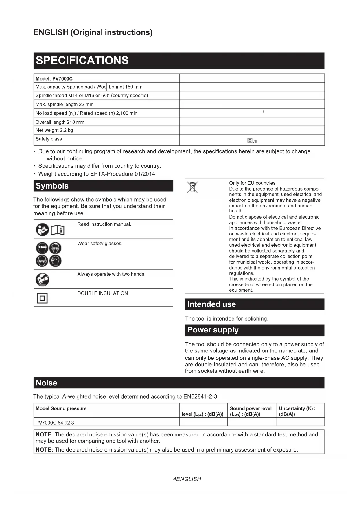
| Model: PV7000C | ||
| Max. capacity Sponge pad / Wool bonnet 180 mm | ||
| Spindle thread M14 or M16 or 5/8" (country specific) | ||
| Max. spindle length 22 mm | ||
| No load speed (n0) / Rated speed (n) 2,100 min | -1 | |
| Overall length 210 mm | ||
| Net weight 2.2 kg | ||
| Safety class | ☐/II | |
- Due to our continuing program of research and development, the specifications herein are subject to change without notice.
- Specifications may differ from country to country.
Weight according to EPTA-Procedure 01/2014
Symbols
The followings show the symbols which may be used for the equipment. Be sure that you understand their meaning before use.


Read instruction manual.


Wear safety glasses.

Always operate with two hands.

DOUBLE INSULATION

Only for EU countries
Due to the presence of hazardous components in the equipment, used electrical and electronic equipment may have a negative impact on the environment and human health.
Do not dispose of electrical and electronic appliances with household waste! In accordance with the European Directive on waste electrical and electronic equipment and its adaptation to national law, used electrical and electronic equipment should be collected separately and delivered to a separate collection point for municipal waste, operating in accordance with the environmental protection regulations.
This is indicated by the symbol of the crossed-out wheeled bin placed on the equipment.
Intended use
The tool is intended for polishing.
Power supply
The tool should be connected only to a power supply of the same voltage as indicated on the nameplate, and can only be operated on single-phase AC supply. They are double-insulated and can, therefore, also be used from sockets without earth wire.
Noise
The typical A-weighted noise level determined according to EN62841-2-3:
| Model Sound pressure | level \( \left( {\mathrm{L}}_{\mathrm{{pA}}}\right) : \left( {\mathrm{{dB}}\left( \mathrm{A}\right) }\right) \) | Sound power level \( \left( {\mathrm{L}}_{\mathrm{{WA}}}\right) : \left( {\mathrm{{dB}}\left( \mathrm{A}\right) }\right) \) | Uncertainty (K) : (dB(A)) |
| PV7000C 84 92 3 |
NOTE: The declared noise emission value(s) has been measured in accordance with a standard test method and may be used for comparing one tool with another.
NOTE: The declared noise emission value(s) may also be used in a preliminary assessment of exposure.
WARNING: Wear ear protection.
WARNING: The noise emission during actual use of the power tool can differ from the declared value(s) depending on the ways in which the tool is used especially what kind of workpiece is processed.
WARNING: Be sure to identify safety measures to protect the operator that are based on an estimation of exposure in the actual conditions of use (taking account of all parts of the operating cycle such as the times when the tool is switched off and when it is running idle in addition to the trigger time).
WARNING: Set heavy flexible damping mats or such to workpieces (thin sheets of metal or other easily vibrating structures with a large surface) to prevent them from emitting sound.
Take the increased noise emission into consideration for both the risk assessment of noise exposure and selecting adequate hearing protection.
Vibration
The vibration total value (tri-axial vector sum) determined according to EN62841-2-3:
Work mode: polishing
| Model | Vibration emission \( \left( {{a}_{n},p}\right) : \left( {\mathrm{m}/{\mathrm{s}}^{2}}\right) \) | Uncertainty (K) : \( \left( {\mathrm{m}/{\mathrm{s}}^{2}}\right) \) |
| PV7000C 2.5 m/s | \( {}^{2} \) or less 1.5 |
NOTE: The declared vibration total value(s) has been measured in accordance with a standard test method and may be used for comparing one tool with another.
NOTE: The declared vibration total value(s) may also be used in a preliminary assessment of exposure.
WARNING: The vibration emission during actual use of the power tool can differ from the declared value(s) depending on the ways in which the tool is used especially what kind of workpiece is processed.
WARNING: Be sure to identify safety measures to protect the operator that are based on an estimation of exposure in the actual conditions of use (taking account of all parts of the operating cycle such as the times when the tool is switched off and when it is running idle in addition to the trigger time).
WARNING: The declared vibration emission value is used for main applications of the power tool. However if the power tool is used for other applications, the vibration emission value may be different.
EC Declaration of Conformity
For European countries only
The EC declaration of conformity is included as Annex A to this instruction manual.
SAFETYWARNINGS
General power tool safety warnings
WARNING: Read all safety warnings, instructions, illustrations and specifications provided with this power tool. Failure to follow all instructions listed below may result in electric shock, fire and/or serious injury.
Save all warnings and instructions for future reference.
The term "power tool" in the warnings refers to your mains-operated (corded) power tool or battery-operated (cordless) power tool.
Polisher safety warnings
Safety warnings common for polishing operations:
- This power tool is intended to function as a polisher. Read all safety warnings, instructions, illustrations and specifications provided with this power tool. Failure to follow all instructions listed below may result in electric shock, fire and/or serious injury.
- Operations such as grinding, sanding, wire brushing, hole cutting or cutting-off are not to be performed with this power tool. Operations for which the power tool was not designed may create a hazard and cause personal injury.
- Do not convert this power tool to operate in a way which is not specifically designed and specified by the tool manufacturer. Such a conversion may result in a loss of control and cause serious personal injury.
- Do not use accessories which are not specifically designed and specified by the tool manufacturer. Just because the accessory can be attached to your power tool, it does not assure safe operation.
- The rated speed of the accessory must be at least equal to the maximum speed marked on the power tool. Accessories running faster than their rated speed can break and fly apart.
-
The outside diameter and the thickness of your accessory must be within the capacity rating of your power tool. Incorrectly sized accessories cannot be adequately guarded or controlled.
-
The dimensions of the accessory mounting must fit the dimensions of the mounting hardware of the power tool. Accessories that do not match the mounting hardware of the power tool will run out of balance, vibrate excessively and may cause loss of control.
- Do not use a damaged accessory. Before each use inspect the accessory such as abrasive wheels for chips and cracks, backing pad for cracks, tear or excess wear, wire brush for loose or cracked wires. If power tool or accessory is dropped, inspect for damage or install an undamaged accessory. After inspecting and installing an accessory, position yourself and bystanders away from the plane of the rotating accessory and run the power tool at maximum no-load speed for one minute. Damaged accessories will normally break apart during this test time.
- Wear personal protective equipment. Depending on application, use face shield, safety goggles or safety glasses. As appropriate, wear dust mask, hearing protectors, gloves and workshop apron capable of stopping small abrasive or workpiece fragments. The eye protection must be capable of stopping flying debris generated by various applications. The dust mask or respirator must be capable of filtrating particles generated by the particular application. Prolonged exposure to high intensity noise may cause hearing loss.
- Keep bystanders a safe distance away from work area. Anyone entering the work area must wear personal protective equipment. Fragments of workpiece or of a broken accessory may fly away and cause injury beyond immediate area of operation.
- Position the cord clear of the spinning accessory. If you lose control, the cord may be cut or snagged and your hand or arm may be pulled into the spinning accessory.
- Never lay the power tool down until the accessory has come to a complete stop. The spinning accessory may grab the surface and pull the power tool out of your control.
- Do not run the power tool while carrying it at your side. Accidental contact with the spinning accessory could snag your clothing, pulling the accessory into your body.
- Regularly clean the power tool's air vents. The motor's fan will draw the dust inside the housing and excessive accumulation of powdered metal may cause electrical hazards.
- Do not operate the power tool near flammable materials. Sparks could ignite these materials.
- Do not use accessories that require liquid coolants. Using water or other liquid coolants may result in electrocution or shock.
Kickback and related warnings:
Kickback is a sudden reaction to a pinched or snagged rotating wheel, backing pad, brush or any other accessory. Pinching or snagging causes rapid stalling of the rotating accessory which in turn causes the uncontrolled power tool to be forced in the direction opposite of the accessory's rotation at the point of the binding.
For example, if an abrasive wheel is snagged or pinched by the workpiece, the edge of the wheel that is entering into the pinch point can dig into the surface of the material causing the wheel to climb out or kick out. The wheel may either jump toward or away from the operator, depending on direction of the wheel's movement at the point of pinching. Abrasive wheels may also break under these conditions. Kickback is the result of power tool misuse and/or incorrect operating procedures or conditions and can be avoided by taking proper precautions as given below.
- Maintain a firm grip with both hands on the power tool and position your body and arms to allow you to resist kickback forces. Always use auxiliary handle, if provided, for maximum control over kickback or torque reaction during start-up. The operator can control torque reactions or kickback forces, if proper precautions are taken.
- Never place your hand near the rotating accessory. Accessory may kickback over your hand.
- Do not position your body in the area where power tool will move if kickback occurs. Kickback will propel the tool in direction opposite to the wheel's movement at the point of snagging.
- Use special care when working corners, sharp edges, etc. Avoid bouncing and snagging the accessory. Corners, sharp edges or bouncing have a tendency to snag the rotating accessory and cause loss of control or kickback.
- Do not attach a saw chain woodcarving blade, segmented diamond wheel with a peripheral gap greater than 10mm or toothed saw blade. Such blades create frequent kickback and loss of control.
Safety warnings specific for polishing operations:
- Do not allow any loose portion of the polishing bonnet or its attachment strings to spin freely. Tuck away or trim any loose attachment strings. Loose and spinning attachment strings can entangle your fingers or snag on the workpiece.
Additional SafetyWarnings:
- Do not leave the tool running. Operate the tool only when hand-held.
- Observe the instructions of the manufacturer for correct mounting and use of accessories. Handle and store accessories with care.
- Check that the workpiece is properly supported.
- If working place is extremely hot and humid, or badly polluted by conductive dust, use a short-circuit breaker (30 mA) to assure operator safety.
- Do not use the tool on any materials containing asbestos.
SAVE THESE INSTRUCTIONS.
WARNING: DO NOT let comfort or familiarity with product (gained from repeated use) replace strict adherence to safety rules for the subject product. MISUSE or failure to follow the safety rules stated in this instruction manual may cause serious personal injury.
FUNCTIONAL DESCRIPTION
CAUTION: Always be sure that the tool is switched off and unplugged before adjusting or checking function on the tool.
Switch action
CAUTION: Before plugging in the tool, always check to see that the switch trigger actuates properly and returns to the "OFF" position when released.
CAUTION: Make sure to switch off the tool in case of a blackout or accidental shut down such as unplugging of the power cord. Otherwise the tool will start unexpectedly when the power supply is recovered and cause an accident or personal injury.
To start the tool, simply pull the switch trigger. Release the switch trigger to stop.
For continuous operation, pull the switch trigger and then push in the lock-on button.
To stop the tool from the locked position, pull the switch trigger fully, then release it.
CAUTION: Switch can be locked in "ON" position for ease of operator comfort during extended use. Apply caution when locking tool in "ON" position and maintain firm grasp on tool.
Fig.1: 1. Lock-on button 2. Switch trigger
Speed adjusting dial
The rotation speed of the tool can be changed by turning the speed adjusting dial. The table below shows the number on the dial and the corresponding rotation speed.
▶ Fig.2: 1. Speed adjusting dial
| Number Speed | |
| 1 600 min | -1 |
| 2 800 min | -1 |
| 3 1,300 min | -1 |
| 4 1,800 min | -1 |
| 5 2,100 min | -1 |
NOTICE: If the tool is operated continuously at low speed for a long time, the motor will get overloaded, resulting in tool malfunction.
NOTICE: The speed adjusting dial can be turned only as far as 5 and back to 1. Do not force it past 5 or 1, or the speed adjusting function may no longer work.
Constant speed control
Possible to get fine finish, because the rotating speed is kept constantly even under the loaded condition.
Soft start feature
Soft start feature reduces starting reaction.
High-Low speed setting button
The tool speed can be changed instantly while the tool is running.
Depress the "I" position for lowest speed, and depress "II" position for a given number setting.
The tool speed cannot be changed when the button is in "I" position, even if you turn the speed adjusting dial. When you turn the speed adjusting dial, always be sure that the button is depressed in "II" position.
Fig.3: 1. High-Low speed setting button
ASSEMBLY
CAUTION: Always be sure that the tool is switched off and unplugged before carrying out any work on the tool.
Installing side grip (handle) and cover
CAUTION: Always be sure that the side grip is installed securely before operation.
Install the cover, then screw the side grip on the tool securely.
The side grip and the cover can be installed on either side of the tool.
Fig.4: 1. Cover 2. Side grip
Fig.5: 1. Cover 2. Side grip
Installing or removing backing pad
Optional accessory
Hold the spindle with the wrench so that the spindle cannot revolve.
Then screw the backing pad onto the spindle all the way. (The backing pad can be used to install the optional sponge pad.)
Fig.6: 1. Backing pad 2. Spindle 3. Wrench
To remove the backing pad, follow the installation procedure in reverse.
Installing or removing sponge pad
Optional accessory
Fig.7: 1. Sponge pad 2. Backing pad
- To install the sponge pad, remove all dirt or foreign matter from the backing pad.
- Install the sponge pad to the backing pad.
To remove the sponge pad, pull it off from the backing pad slowly.
Installing or removing wool bonnet
Optional accessory
▶ Fig.8: 1. Wool bonnet 2. Lock nut 3. Rubber pad 4. Spindle
- Mount the rubber pad onto the spindle. Screw the lock nut onto the spindle.
- To tighten the lock nut, hold the spindle with the wrench so that the spindle cannot revolve, then use the lock nut wrench and securely tighten clockwise.
Fig.9: 1. Lock nut wrench 2. Wrench
3. Fit the wool bonnet completely over the rubber pad, and pull the string tight. Tie a bow knot and tuck the knot and any loose strings between the wool bonnet and the rubber pad.
Fig.10
To remove the wool bonnet, follow the installation procedure in reverse.
OPERATION
CAUTION: Always wear safety goggles or a face shield during operation.
CAUTION: ALWAYS hold the tool firmly with one hand on housing and the other on the side grip (handle).
Polishing operation by sponge pad
Fig.11
In general, keep the sponge pad at an angle of about 15 degrees to the workpiece surface.
Polishing operation by wool bonnet
Fig.12
Turn the tool on and then apply the wool bonnet to the workpiece. In general, keep the wool bonnet at an angle of about 15 degrees to the workpiece surface.
Apply slight pressure only. Excessive pressure will result in poor performance and premature wear to the wool bonnet.
MAINTENANCE
CAUTION: Always be sure that the tool is switched off and unplugged before attempting to perform inspection or maintenance.
NOTICE: Never use gasoline, benzine, thinner, alcohol or the like. Discoloration, deformation or cracks may result.
To maintain product SAFETY and RELIABILITY, repairs, any other maintenance or adjustment should be performed by Makita Authorized or Factory Service Centers, always using Makita replacement parts.
Replacing carbon brushes
Fig.13: 1. Limit mark
Check the carbon brushes regularly.
Replace them when they wear down to the limit mark. Keep the carbon brushes clean and free to slip in the holders. Both carbon brushes should be replaced at the same time. Use only identical carbon brushes.
- Use a screwdriver to remove the brush holder caps.
- Take out the worn carbon brushes, insert the new ones and secure the brush holder caps.
Fig.14: 1. Brush holder cap 2. Screwdriver
OPTIONAL ACCESSORIES
CAUTION: These accessories or attachments are recommended for use with your Makita tool specified in this manual. The use of any other accessories or attachments might present a risk of injury to persons. Only use accessory or attachment for its stated purpose.
If you need any assistance for more details regarding these accessories, ask your local Makita Service Center.
- Side grip
- Sponge pad (hook-and-loop)
- Backing pad 165 (hook-and-loop)
- Wool bonnet 180
Wrench
Rubber pad - Lock nut
- Lock nut wrench
NOTE: Some items in the list may be included in the tool package as standard accessories. They may differ from country to country.
SPECIFICATIONS
ACCESSIONS EN OPTION
VEILIGHEIDSWAARSCHUWINGEN
OPTIONELE ACCESSOIRES
Eik.13: 1. Evdi ngopiou
Na eAeYxETa KaPbouvakia TAKTIKA.
Avtikataahtote ta otav apouv expi to onmuabi opiou.
Aiatnpite ta kapbouvacia kaopapa kai euethetapa va
yiatpouv stic hkec. Ka ta duo kapbouvacia npetie
va avtikaiotavtai tautoxpova. Xpnoiottoiee movo
kapbouvacia idou tuTou.
- Xpnoiopoioiote eva kaotaojiyia va aqaipoeoTe Ta kattakia twv thkowkapouvakiw.
- ApaipoeTe Ta aepuEva KapBouvacia, TOToETn-ote Ta Kaivoupiia Kai aopalote Ta kattakia Twv KapBouvakw.
Eik.14: 1. KaTaki OngKc KApBouvakiou 2. KatOaBi
ΠPOAIPETIKA ΕΑPTHMATA
A NPOEOXH: Auta ta agptnmuata n npoaptnmuata ouviotwvai ia xpno n e to epyaaleio Makita Tou TepiypapntkE OTIC oyniec autc. H xpno otoiowbnttoe aalwwv egaptnmuatvw n npoapntmuatw v tpokaeaei kivduvo tpaumiaou o et aotua. Na xpnoioutoeite ta egaptnmuata n npoaprtnmuata mvo yia tvx npoan Tou npoopicovtai.
Eav xpeiaeote oioahtote Bontheia yia TepiooTepec PAnpoopoeis oe oxen me auta ta Eapntmuata, aTotav-0e iTO tNIKOAC KevIPO ESUTnpETnOc Makita.