LH1040F - Electric saw MAKITA - Free user manual and instructions
Find the device manual for free LH1040F MAKITA in PDF.
| Product type | Combined power saw (radial miter saw and table circular saw) |
| Brand | Makita |
| Model | LH1040F |
| Blade diameter | 255 mm – 260 mm |
| Blade body thickness | 1.6 mm – 1.8 mm |
| Bore diameter (outside Europe) | 25.4 mm and 25 mm |
| Bore diameter (Europe) | 30 mm |
| No-load speed | 4,800 min⁻¹ |
| Max. cutting capacity (miter saw, 260 mm blade, bevel 0°, miter 0°) | 69 mm (H) × 130 mm (W) |
| Max. cutting capacity (table circular saw) | 40 mm (thickness) |
| Table dimensions | 260 mm × 405 mm |
| Dimensions (L × W × H) | 530 mm × 476 mm × 535 mm |
| Net weight | 14.3 kg |
| Protection class | I |
| Power supply | Single-phase current, double insulation, no earth connection |
| Sound pressure level (LpA) | 93 dB(A) |
| Sound power level (LWA) | 107 dB(A) |
| Vibrations (total value) | ≤ 2.5 m/s² |
| Lighting | Integrated lamp (model LH1040F) |
| Safety device | Lower and upper blade guards, riving knife, shaft lock |
| Dust extraction system | Connection for vacuum cleaner and dust bag supplied |
| Maintenance | Clean guards with a damp cloth; replace brushes regularly; lubricate sliding parts |
| Accessories included | Blade, auxiliary plate, dust bag, socket wrench, side tables, push stick, etc. |
| Intended uses | Precision cutting of wood and aluminum (no ferrous metals) |
Frequently Asked Questions - LH1040F MAKITA
User questions about LH1040F MAKITA
0 question about this device. Answer the ones you know or ask your own.
Ask a new question about this device
Download the instructions for your Electric saw in PDF format for free! Find your manual LH1040F - MAKITA and take your electronic device back in hand. On this page are published all the documents necessary for the use of your device. LH1040F by MAKITA.
USER MANUAL LH1040F MAKITA
GB Table Top Miter Saw Instruction Manual
F Scie à Onglets à Table Supérieure Manuel d'instructions
D Universal-Kapp- und Gehrungssäge Betriebsanleitung
I Sega da banco con pianetto Istruzioni per l'uso
NL Tafel-, afkort- en verstekzaag Gebruiksaanwijzing
E Sierra de Inglete con Banco Manual de instructiones
P Serra de esquadria de mesa Manual de instruções
DK Bord-geringssav Brugsanvisning
GR Emipanézio loe npiovi Odyiec xpnoewc
LH1040
LH1040F


1

015235 001832
3

015236 015237
5
015238 005534
7
005535 005536


11 12 015240 005539

13 14 005540 005541
15 16 012648 012646

17 18
012647 005545

1920
005544 005546
21 22
005547 005548
23 24

005549 015241

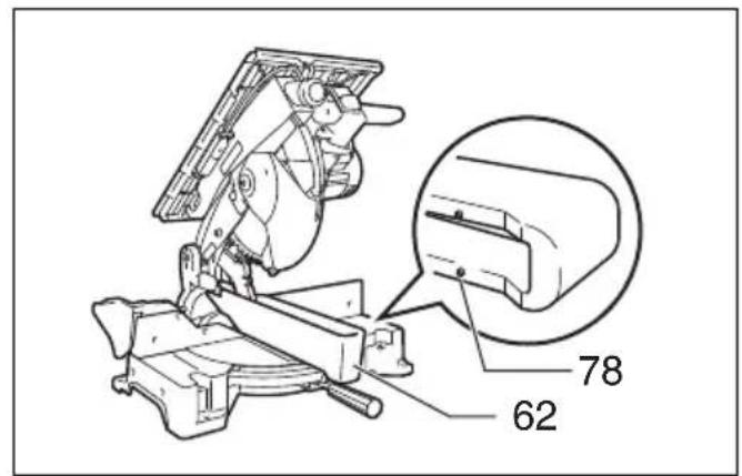
25 26
005551 005553
27 28

005554 005555
2930
005552 005556
31 32
005557 005558

33 34
005559 005560
35 36
005561 001549


37 38
015243 012655
39 40
001807 012656
41 42
002246 005562

43 44

005563 001844
45 46
012657 015244
47 48
005566 005565
4950
005706 005567

51 52
005569 012646
53 54
012650 015245


55 56
015246 005573
57 58

010798 005574

5960
005575 001145
61

005576
END208-8
Symbols
The followings show the symbols used for the equipment. Be sure that you understand their meaning before use.
Symboles
- Only for EU countries
Due to the presence of hazardous components in the equipment, used electrical and electronic equipment may have a negative impact on the environment and human health.
Do not dispose of electrical and electronic appliances with household waste!
In accordance with the European Directive on waste electrical and electronic equipment and its adaptation to national law, used electrical and electronic equipment should be collected separately and delivered to a separate collection point for municipal waste, operating in accordance with the environmental protection regulations.
This is indicated by the symbol of the crossed-out wheeled bin placed on the equipment.
- Movyia tis xwpe ts EE
Aoyw TnC napouiaacTwv ENIKivduvw ouotatikov eepowv oTov EeONlaioo, O xpnaiomoinevoc nEeKTpiokc kai nEeKtpovikoc EeONlaiooic mnoei va exi apvntikn Etnibpaon oTo nepiBaaov kai tnV avpwnivuyeia.
Mny anoppinTETc nAektpiKcKaI nAektpovikc oukeuεc maiz ta oiklaka anoppipmuata!
Explanation of general view
| 1 Auxiliary plate | 32 Center cover | 63 Support |
| 2 Hex b ol t ( | 83 Blade guard A | 64 Turn base |
| 3 Base | 34 Shaft lock | 65 Sub-fence |
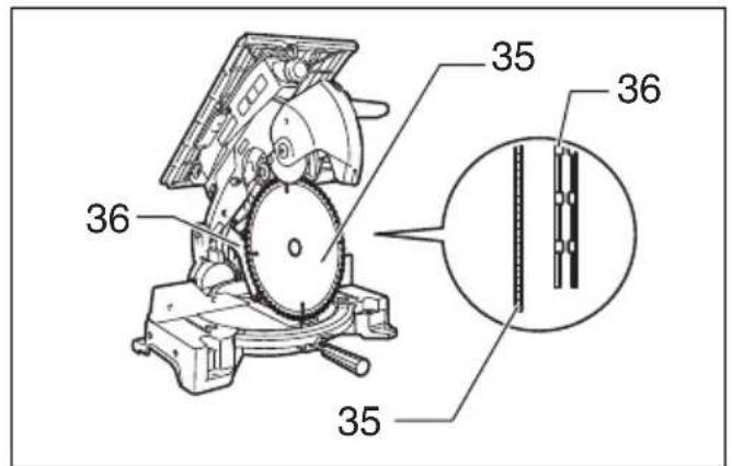
| 4 N u t | 35 Saw blade | 66 Vise rod |
| 5 Holders | 36 Blade guard B | 67 Vise knob |
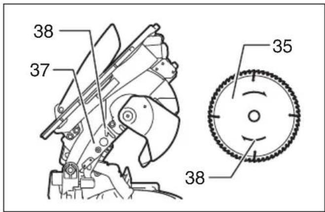
| 6 Holder | 37 Blade case | 68 Vise arm |
| 7 Adjuster | 38 Arrow | 69 Holder assembly |
| 8 S c r ew | 39 Outer flange | 70 Projection |
| 9 B o l t | 40 Inner flange | 71 Vise shaft |
| 10 Lower blade guard A | 41 Spindle | 72 Rod 12 |
| 11 Lower blade guard B | 42 Ring | 73 Vise (optional accessory) |
| 12 Top blade guard | 43 Riving knife | 74 Vise |
| 13 Handle | 44 Area to press in | 75 Spacer block |
| 14 Lever | 45 Blade width | 76 Aluminum extrusion |
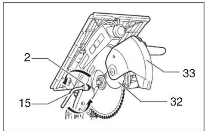
| 15 Socket wrench | 46 Rip fence holder | 77 Set plate |
| 16 Adjusting bolt | 47 Guide rail on the top table | 78 Small boss |
| 17 Top surface of turn base | 48 Clamping screw (A) | 79 Face/edge parallel |
| 18 Periphery of blade | 49 Clamping screw (B) | 80 Wood screw |
| 19 Guide fence | 50 Rip fence | 81 Glue together |
| 20 Pointer | 51 Workpiece | 82 Hole (7 mm in diameter) |
| 21 Lock lever | 52 Line to be aligned with | 83 Bolt M6 |
| 22 Grip | 53 Square nut | 84 Push stick |
| 23 Miter scale | 54 Washer | 85 Auxiliary fence |
| 24 Bevel scale | 55 Scale | 86 Push block |
| 25 Switch | 56 Two screws | 87 Triangular rule |
| 26 Lamp switch | 57 Dust nozzle | 88 0° adjusting bolt |
| 27 Lamps | 58 Dust bag | 89 Arm |
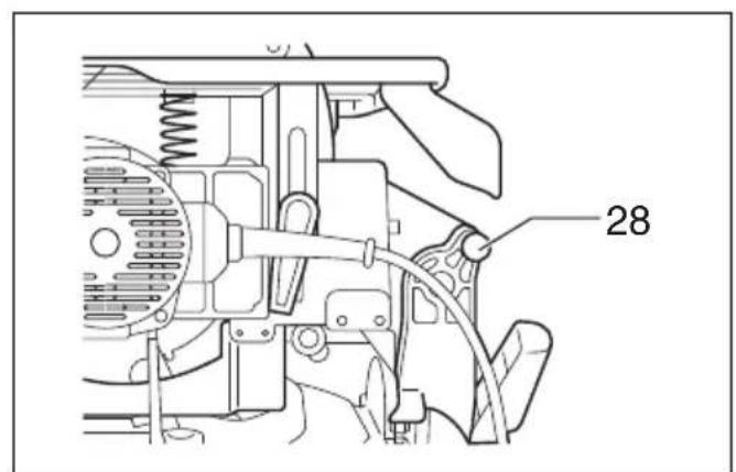
| 28 Stopper pin | 59 Fastener | 90 45° bevel angle adjusting bolt |
| 29 Clamping screw | 60 Cap | 91 Limit mark |
| 30 Top table | 61 Vacuum cleaner | 92 Screwdriver |
| 31 Motor housing | 62 Blade cover | 93 Brush holder cap |
SPECIFICATIONS
Model LH1040/LH1040F
Blade diameter 255 mm - 260 mm
Blade body thickness 1.6 mm - 1.8 mm
Riving knife thickness 2.0 mm
Hole diameter
For all countries other than European countries 25.4 mm and 25 mm
For European countries 30 mm
Max. Cutting capacities (H x W) with blade 260 mm in diameter in the miter saw mode
| Bevel angle | Miter angle | |
| 0° 45° | ||
| 0° | 69 mm x 130 mm | right 69 mm x 85 mm, 93 mm x 67 mm |
| 93 mm x 95 mm | left 69 mm x 85 mm, 93 mm x 67 mm | |
| 45° (left) | 35 mm x 130 mm | right 35 mm x 91 mm, 49 mm x 67 mm |
| 53 mm x 95 mm | left 35 mm x 65 mm, 49 mm x 42 mm | |
Max. Cutting capacities at 90^ in the table saw (bench saw mode) 40 mm
No load speed (^-1) 4,800
Table size (W x L) 260 mm x 405 mm
Dimensions (L x W x H) 530 mm x 476 mm x 535 mm
Net weight 14.3kg
Safety class.
- Due to our continuing program of research and development, the specifications herein are subject to change without notice.
- Specifications may differ from country to country.
Weight according to EPTA-Procedure 01/2003
Intended use
The tool is intended for accurate straight cutting and (only when used as a miter saw on the lower table) miter cutting in wood.
ENF002-2
Power supply
The tool should be connected only to a power supply of the same voltage as indicated on the nameplate, and can only be operated on single-phase AC supply. They are double-insulated and can, therefore, also be used from sockets without earth wire.
GEA010-1
General Power Tool SafetyWarnings
WARNING Read all safety warnings and all instructions. Failure to follow the warnings and instructions may result in electric shock, fire and/or serious injury.
Save all warnings and instructions for future reference.
ENB088-5
TABLE TOP MITER SAW SAFETY WARNINGS FOR BOTH MITER SAW MODE AND TABLE SAW (BENCH SAW) MODE
- Check the blade carefully for cracks or deformation before operation. Replace damaged blade immediately.
- Do not operate saw without guards and riving knife in place, especially after a mode change. Check blade guards for proper closing before each use. Do not operate saw if blade guards do not move freely and close instantly. Never clamp or tie the blade guards into the open position. Any irregular operation of the blade guards should be corrected immediately.
- Use only saw blades specified by the manufacturer and which conform to EN847-1. The groove width of the cut must be thicker than the riving knife and the blade body must be thinner than the riving knife.
- Do not use saw blades manufactured from high speed steel.
- Wear eye protection.
- Wear hearing protection to reduce the risk of hearing loss.
- Wear gloves for handling saw blades (saw blades shall be carried in a holder wherever practicable) and rough material.
- Connect the tool to a dust collecting device when sawing.
- Always store the push-stick when it is not in use.
- Keep the floor area around the tool level well maintained and free of loose materials e.g. chips and cut-offs.
- The operator is adequately trained in the use, adjustment and operation of the tool.
- Stop and unplug the saw when unattended.
- To reduce the emitted noise, always be sure that the blade is sharp and clean.
- Use only saw blades that are marked with a maximum speed equal to or higher than the no load speed marked on the tool.
-
When the tool is fitted with a laser or LED, do not replace the laser or LED with a different type. Ask an authorized service center for repair.
-
Never remove any cut-offs or other parts of the workpiece from the cutting area whilst the tool is running with an unguarded saw blade.
- The tool should not be used for slotting, rebating or grooving.
- Before carrying the tool, always cover the upper part of the saw blade by the top guard and secure all moving portions. When lifting or carrying the tool, do not use the guard as a carrying handle.
- Clean and be careful not to damage the spindle, flanges (especially the installing surface) and hex bolt before or when installing the blade. Damage to these parts could result in blade breakage. Poor installation may cause vibration/ wobbling or slippage of the blade. Use only flanges specified for this tool.
- Always use accessories recommended in this manual. Use of improper accessories such as abrasive cut-off wheels may cause an injury.
- Select the correct saw blade for the material to be cut.
- Do not cut metal objects such as nails and screws. Inspect for and remove all nails, screws and other foreign material from the workpiece before operation.
- Knock out any loose knots from workpiece BEFORE beginning to cut.
- Do not use the tool in the presence of flammable liquids or gases.
- For your safety, remove the chips, small pieces, etc. from the work area and table top before plugging the tool and starting operation.
- Keep hands and make your bystander and yourself position out of path of and not in line with saw blade. Avoid contact with any coasting blade. It can still cause severe injury and never reach around saw blade.
- Be alert at all times, especially during repetitive, monotonous operations. Do not be lulled into a false sense of security. Blades are extremely unforgiving.
- Make sure the shaft lock is released before the switch is turned on.
- Before using the tool on an actual workpiece, let it run for a while. Watch for vibration or wobbling that could indicate poor installation or a poorly balanced blade.
- Wait until the blade attains full speed before cutting.
- Stop operation immediately if you notice anything abnormal.
- Turn off tool and wait for saw blade to stop before moving workpiece or changing settings.
-
Unplug tool before changing blade, servicing or not in use.
-
Some dust created from operation contains chemicals known to cause cancer, birth defects or other reproductive harm. Some examples of these chemicals are:
-
lead from lead-based-painted material and,
- arsenic and chromium from chemically-treated lumber.
Your risk from these exposures varies, depending on how often you do this type of work. To reduce your exposure to these chemicals: work in a well ventilated area and work with approved safety equipment, such as those dust masks that are specially designed to filter out microscopic particles.
-
Even when the tool is used as prescribed it is not possible to eliminate all residual risk factors. The following hazards may arise in connection with the tool's construction and design:
-
Damage to health resulting from hand-arm vibrations if the power tool is used over a longer period of time and is not operated or serviced correctly.
- Injury or damage caused by loose tool attachments which can unexpectedly slide out/from the power tool due to sudden damage, wear or improper mounting.
WHEN USING IN MITER SAW MODE:
- Replace the kerf board when worn.
- Use a push stick or a push block to avoid working with the hands and fingers close to the saw blade.
- Make sure that the arm is securely fixed when beveling. Tighten the lever clockwise to fix the arm.
- Do not perform any operation freehand. The workpiece must be secured firmly against the turn base and guide fence with the vise during all operations. Never use your hand to secure the workpiece.
- Ensure that the tool is stable before each cut.
- Fix the tool to a work bench, if needed.
- Support long workpieces with appropriate additional supports.
- Never cut so small workpiece which cannot be securely held by the vise. Improperly held workpiece may cause kickback and serious personal injury.
- Do not use the saw to cut other than wood, aluminum or similar materials.
- Make sure that the turn base is properly secured so it will not move during operation.
- Make sure the blade does not contact the turn base in the lowest position and is not contacting the workpiece before the switch is turned on.
- Hold the handle firmly. Be aware that the saw moves up or down slightly during start-up and stopping.
WHEN USING IN THE TABLE SAW (BENCH SAW) MODE:
- Make sure that the arm is securely fixed in the working position. Tighten the lever clockwise to fix the arm.
- Make sure that the bench saw table is securely fixed at the chosen height.
-
Do not perform any operation freehand. Freehand means using your hands to support or guide the workpiece, in lieu of a rip fence.
-
Make sure the blade is not contacting the riving knife or workpiece before the switch is turned on.
- Pay particular attention to instructions for reducing risk of KICKBACK. KICKBACK is a sudden reaction to a pinched, bound or misaligned saw blade. KICKBACK causes the ejection of the workpiece from the tool back towards the operator. KICKBACKS CAN LEAD TO SERIOUS PERSONAL INJURY. Avoid KICKBACKS by keeping the blade sharp, by keeping the rip fence parallel to the blade, by keeping the riving knife and blade guard in place and operating properly, by not releasing the workpiece until you have pushed it all the way past the blade, and by not ripping a workpiece that is twisted or warped or does not have a straight edge to guide along the fence.
- Avoid abrupt, fast feeding. Feed as slowly as possible when cutting hard workpieces. Do not bend or twist workpiece while feeding. If you stall or jam the blade in the workpiece, turn the tool off immediately. Unplug the tool. Then clear the jam.
SAVE THESE INSTRUCTIONS.
WARNING:
DO NOT let comfort or familiarity with product (gained from repeated use) replace strict adherence to safety rules for the subject product. MISUSE or failure to follow the safety rules stated in this instruction manual may cause serious personal injury.
INSTALLATION
CAUTION:
- Keep the floor area around the tool level well maintained and free of loose materials such as chips and cut-offs.
Installing auxiliary plate (Fig. 1 & 2)
Always install the auxiliary plate using the notch in the tool's base and secure it by tightening the hex bolt before operation.
For European countries
Installing the holders (Fig. 3 & 4)
Install the holders on both sides of the base and secure them with screws.
Adjust the adjusters so that they contact the floor surface.
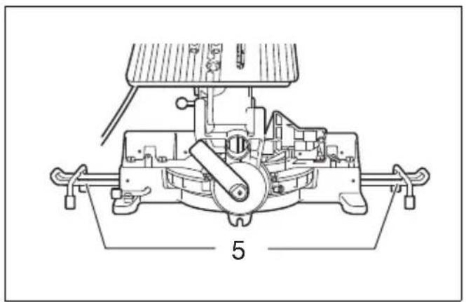
Bench mounting (Fig. 5)
This tool should be bolted with two bolts to a level and stable surface using the bolt holes provided in the tool's base. This will help prevent tipping and possible injury.
FUNCTIONAL DESCRIPTION
CAUTION:
- Always be sure that the tool is switched off and unplugged before adjusting or checking function on the tool.
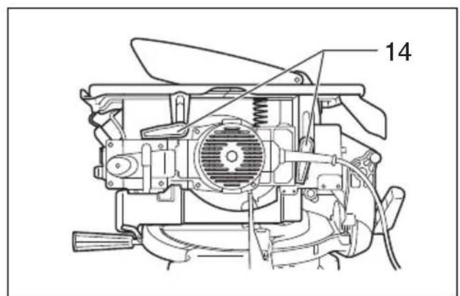
Blade guard (Fig. 6 & 7)
CAUTION:
-
Make sure that the handle cannot be lowered without pushing the lever nearby the handle to the left.
-
Make sure that the lower blade guards A and B dose not open unless the lever near the handle is pushed at the topmost position of the handle.
When lowering the handle while pushing the lever to the left, the lower blade guard A rises automatically. The lower blade guard B rises as it contacts a workpiece. The lower blade guards are spring loaded so it returns to its original position when the cut is completed and the handle is raised. The top blade guard falls flat on the top surface after workpiece has passed under it. NEVER DEFEAT OR REMOVE THE LOWER BLADE GUARDS, THE SPRING WHICH ATTACHES TO THE LOWER BLADE GUARD, OR THE TOP BLADE GUARD.
In the interest of your personal safety, always maintain each blade guard in good condition. Any irregular operation of the guards should be corrected immediately. Check to assure spring loaded return action of the lower blade guards. NEVER USE THE TOOL IF THE LOWER BLADE GUARD, SPRING OR THE TOP BLADE GUARD ARE DAMAGED, FAULTY OR REMOVED. DOING SO IS HIGHLY DANGEROUS AND CAN CAUSE SERIOUS PERSONAL INJURY.
If any of these see-through blade guards becomes dirty, or sawdust adheres to it in such a way that the blade is no longer easily visible, unplug the saw and clean the guards carefully with a damp cloth. Do not use solvents or any petroleum-based cleaners on the plastic guard.
If the lower blade guard A is especially dirty and vision through the guard is impaired, proceed as follows. Fix the top table at the fully elevated position, raise the handle fully, push in fully the stopper pin with the handle fully raised, and use the supplied socket wrench to loosen the hex bolt holding the center cover. Loosen the hex bolt by turning it counterclockwise and raise the lower blade guard A and center cover while pushing the lever to the left. With the lower blade guard A so positioned, cleaning can be more completely and efficiently accomplished. When cleaning is complete, reverse procedure above and secure bolt.
In the same case for the top blade guard as above stated, loosen the screw holding it with a screwdriver and remove the top blade guard. After cleaning, always reinstall it securely by tightening the screw to the extent that the top blade guard moves smoothly up or down.
If any of these blade guards becomes discolored through age or UV light exposure, contact a Makita service center for a new guard. DO NOT DEFEAT OR REMOVE GUARDS.
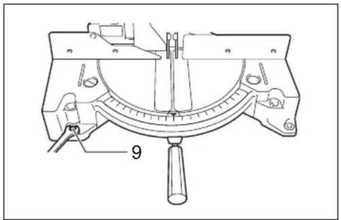
Maintaining maximum cutting capacity (Fig. 8 & 9)
This tool is factory adjusted to provide the maximum cutting capacity for a 260~mm saw blade.
When installing a new blade, always check the lower limit position of the blade and if necessary, adjust it as follows:
CAUTION:
- When making this adjustment, position the top table at the lowest position after unplugging the tool.
First, unplug the tool. Position the top table at the lowest position. Lower the handle completely. Use the socket wrench to turn the adjusting bolt that you can find below in the biggest hole in the top table, until the periphery of the blade extends slightly below the top surface of the turn base at the point where the front face of the guide fence meets the top surface of the turn base.
With the tool unplugged, rotate the blade by hand while holding the handle all the way down to be sure that the blade does not contact any part of the lower base. Readjust slightly, if necessary.
CAUTION:
- After installing a new blade, always be sure that the blade does not contact any part of the lower base when the handle is lowered completely. Always do this with the tool unplugged.
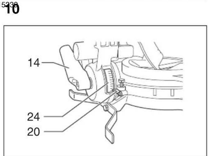
Adjusting the miter angle (Fig. 10)
Loosen the grip by turning counterclockwise. Turn the turn base while pressing down the lock lever. When you have moved the grip to the position where the pointer points to the desired angle on the miter scale, securely tighten the grip clockwise.
CAUTION:
- When turning the turn base, be sure to raise the handle fully.
After changing the miter angle, always secure the turn base by tightening the grip firmly.
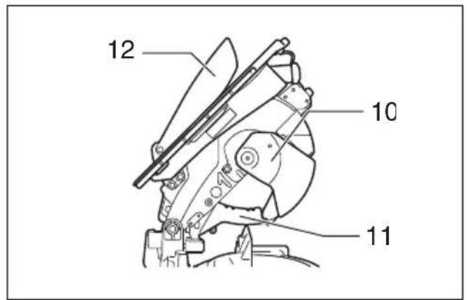
Adjusting the bevel angle (Fig. 11 & 12)
To adjust the bevel angle, loosen the lever at the rear of the tool counterclockwise.
Push the handle to the left to tilt the saw blade until the pointer points to the desired angle on the bevel scale.
Then tighten the lever clockwise firmly to secure the arm.
CAUTION:
- When tilting the saw blade, be sure to raise the handle fully.
After changing the bevel angle, always secure the arm by tightening the lever clockwise.
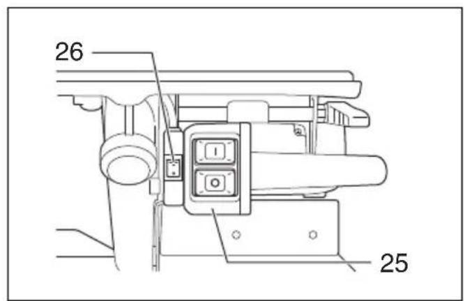
Switch action (Fig. 13)
CAUTION:
- Before operation, make sure that the tool is turned on and off.
To start the tool, press the ON (I) button. To stop it, press the OFF (O) button.
Lighting up the lamps (Fig. 14)
For Model LH1040F only
Push the upper position of the switch for turning on the light and the lower position for off.
CAUTION:
- Do not look in the light or see the source of light directly.
NOTE:
- Use a dry cloth to wipe the dirt off the lens of lamp. Be careful not to scratch the lens of lamp, or it may lower the illumination.
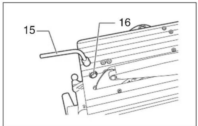
Adjusting the level of top table (Fig. 15)
To adjust the level of top table, loosen two levers by turning counterclockwise and then raise or lower the top table. Tighten these levers firmly after the adjustment.
WARNING:
- Position the top table at the topmost position when using the tool in the miter saw mode and at the desired position when using in the table saw mode (bench mode).
ASSEMBLY
CAUTION:
- Always be sure that the tool is switched off and unplugged before carrying out any work on the tool.
Installing or removing saw blade
CAUTION:
- Always be sure that the tool is switched off and unplugged before installing or removing the blade.
- Use only the Makita socket wrench provided to install or remove the blade. Failure to do so may result in overtightening or insufficient tightening of the hex bolt. This could cause an injury.
Secure the top table at the topmost position.
Lock the handle in the raised position by pushing in the stopper pin. (Fig. 16)
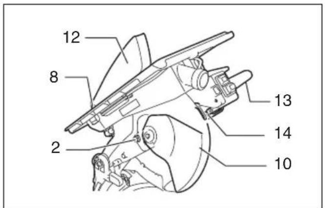
To remove the blade, first loosen the clamping screw so that the lower blade guard B is lowered as shown in the figure. (Fig. 17)
Then use the socket wrench to loosen the hex bolt holding the center cover by turning it counterclockwise. Raise the lower blade guard A and center cover while pushing the lever nearby the handle to the left. (Fig. 18)
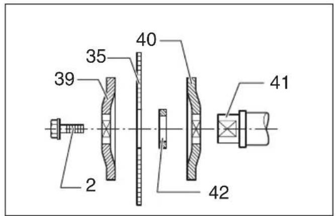
Press the shaft lock to lock the spindle, use the socket wrench to loosen the hex bolt clockwise. Then remove the hex bolt, outer flange and blade. (Fig. 19)
To install the blade, mount it carefully onto the spindle, making sure that the direction of the arrow on the surface of the blade matches the direction of the arrow on the blade case. Install the outer flange and hex bolt, and then use the socket wrench to tighten the hex bolt (left-handed) securely counterclockwise while pressing the shaft lock. (Fig. 20 & 21)
NOTE:
- When installing a saw blade, be sure to insert it from the outside of the blade guard B at first and then raise it so that the blade is finally placed in the blade guard B.
CAUTION:
- The ring 25.0mm or 30mm in outer diameter is factory-installed onto the spindle. Before mounting the blade onto the spindle, always be sure that the correct ring for the arbor hole of the blade you intend to use is installed onto the spindle. (Fig. 22)
Return the lower blade guard A and center cover to its original position. Then tighten the hex bolt clockwise to secure the center cover. Raise the blade guard B as far as it will go and tighten the clamping screw firmly while holding it in the raised position. Lower the handle to make sure that the lower blade guards move properly. Make sure shaft lock has released spindle before making cut.
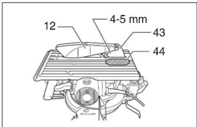
Adjusting riving knife
Before adjusting the riving knife, loosen the two levers by turning counterclockwise and press the top table on the right side nearby the riving knife to its lowered position. Then secure the top table by firmly re-tightening the two levers as shown in the figure. (Fig. 23)
There must be a clearance of about 4 - 5mm between the riving knife and the blade teeth. Adjust the riving knife accordingly by loosening two hex bolts counterclockwise with the hex socket wrench and measuring the distance. Tighten the hex bolts securely, and then check to see that the top blade guard works smoothly before cutting. (Fig. 24)
The riving knife has been installed before shipment from the factory so that the blade and riving knife are in a straight line. (Fig. 25)
CAUTION:
- If the blade and riving knife are not aligned properly, a dangerous pinching condition may result during operation. Make sure the riving knife is positioned between both outer ends of the blade teeth when viewing from the top. You could suffer serious personal injury while using the tool without a properly aligned riving knife. If they are not aligned for any reasons, always have Makita authorized service center repair it.
- Don't remove the riving knife.
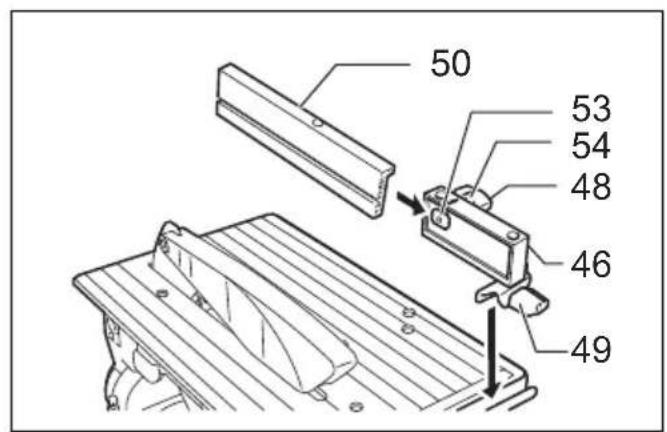
Installing and adjusting rip fence
- Install the rip fence on the table so that the rip fence holder engages with the guide rail. Tighten the clamping screw (B) of the rip fence firmly clockwise.
- Loosen the clamping screw (A).
- Slide the rip fence and secure it so that the far end from you of the rip fence is aligned with the point at which the front edge of saw blade just appears from top surface of the workpiece. The purpose of this adjustment is to reduce risk of kick-back toward operator that cut piece from the workpiece is pinched between the saw blade and rip fence and finally pushed out toward operator. The line 3 varies by thickness of workpiece or the table level. Adjust the position of the rip fence according to the thickness of the workpiece.
After adjusting the rip fence, tighten the clamping screw (A) firmly. (Fig. 26 & 27)
NOTE:
- There are four patterns to position the rip fence as shown in the figure. (Fig. 28) Rip fence has two slits on its sides, one slit with an elevated fringe nearby on the same side and the other without it. Use the surface of rip fence with this fringe facing the workpiece only when cutting off into a piece of a thin workpiece.
- To change the rip fence pattern, remove the rip fence from the rip fence holder by loosening the clamping screw (A) and change the facing of the rip fence to the rip fence holder so that the rip fence faces the rip fence holder according to your work as shown in the figure. (Fig. 29)
Insert the square nut on the rip fence holder into the back end of either slit of the rip fence so that they fit as shown in the figure.
To change from the pattern A or B to the pattern C or D, or in adverse case, remove the square nut, washer and clamping screw (A) from the rip fence holder, then position the clamping screw (A), washer and square nut on the opposite position of the rip fence holder compared to the original position. Tighten the clamping screw (A) securely after inserting the square nut of the rip fence holder into the rip fence slit.
Insert the square nut on the rip fence holder into the back end of either slit of the rip fence so that they fit as shown in the figure.
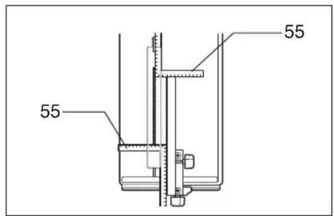
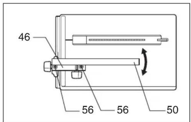
The rip fence is factory adjusted so that it is parallel to the blade surface. Make sure that it is parallel. To check to be sure that the rip fence is parallel with the blade. Lower the table to the lowest position so that the blade appears at the topmost position from the table. Mark one of the blade teeth with a crayon. Measure the distance (A) and (B) between the rip fence and blade. Take both measurements using the tooth marked with the crayon. These two measurements should be identical. If the rip fence is not parallel with the blade, proceed as follows: (Fig. 30 & 31)
(1) Turn two adjusting screws counterclockwise.
(2) Shift the back edge of the rip fence slightly to right or left until it becomes parallel with the blade.
(3) Tighten the two screws on the rip fence firmly.
CAUTION:
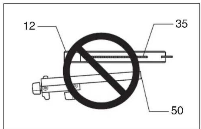
- Be sure to adjust the rip fence so that it is parallel with the blade, or a dangerous kickback condition may occur. (Fig. 32)
- Be sure to adjust the rip fence so that it does not contact the top blade guard or saw blade.
Dust bag
The use of the dust bag makes cutting operations clean and dust collection easy. To attach the dust bag, fit it onto the dust nozzle. (Fig. 33)
NOTE:
- In miter saw mode, always insert the dust bag to the back nozzle only.
When the dust bag is about half full, remove the dust bag from the tool and pull the fastener out. Empty the dust bag of its contents, tapping it lightly so as to remove particles adhering to the insides which might hamper further collection. (Fig. 34)
If you connect a vacuum cleaner to your saw, more efficient and cleaner operations can be performed.
To install the blade cover when using in the table saw mode (bench mode), turn the turn base to 0^ miter angle (see the section titled "Adjusting miter angle") and place the blade cover on the turn table so that the blade cover is centered over the slit for the blade entrance in the turn table and then lock the handle in the lowest position by fully pushing in the stopper pin as shown in the figure. (Fig. 35)
NOTE:
- To attach the dust bag to the front dust nozzle in the table saw mode (bench mode), first remove the cap from the front dust nozzle and then attach the dust bag to the dust nozzle.
- When not in use of dust bag, always replace the cap to the front dust nozzle. Failure to do so result in dust scattering from the nozzle.
- When using the tool in the table saw mode (bench mode), make sure that the blade cover is installed on the turn table.
Securing workpiece
Whenever possible, secure the workpiece with the optional vise. If you must use your hand to hold the workpiece, then it must be done firmly and securely so as not to lose control of the workpiece. Your hand and arm must be kept well away from the blade area (100 mm minimum). Squeeze the workpiece firmly against the guide fence with your fingers held over the top of the guide fence. The workpiece must also rest steadily on the turn base.
WARNING:
- Never use your hand to hold the workpiece that requires your hand to be any closer than 100mm from the blade area. In this case, always use the optional vise to secure the workpiece. After any cutting operation, raise the blade gently. Never raise the blade until it has come to a complete stop. Serious injury may result.
CAUTION:
- When cutting long workpieces, use supports that are as high as the top surface level of the turn base. Do not rely solely on the vertical vise and/or horizontal vise (both optional) to secure the workpiece. (Fig. 36)
Thin material tends to sag. Support workpiece over its entire length to avoid blade pinch and possible KICKBACK.
Sub-fence (for European countries only) (Fig. 37)
This tool is equipped with the sub-fence. Usually position the sub-fence inside. However, when performing left bevel cuts, flip it outward.
CAUTION:
- When performing left bevel cuts, flip the sub-fence outward. Otherwise, it will contact the blade or a part of the tool, causing possible serious injury to the operator.
Vertical vise (optional accessory) (Fig. 38)
The vertical vise can be installed in two positions on either the left or right side of the guide fence or the holder assembly (optional accessory). Insert the vise rod into the hole in the guide fence or the holder assembly and tighten the screw to secure the vise rod.
Position the vise arm according to the thickness and shape of the workpiece and secure the vise arm by tightening the screw. If the screw to secure the vise arm contacts the guide fence, install the screw on the opposite side of vise arm. Make sure that no part of the tool contacts the vise when lowering the handle all the way. If some part contacts the vise, re-position the vise.
Press the workpiece flat against the guide fence and the turn base. Position the workpiece at the desired cutting position and secure it firmly by tightening the vise knob.
CAUTION:
- The workpiece must be secured firmly against the turn base and guide fence.
Horizontal vise (optional accessory) (Fig. 39)
The horizontal vise can be installed on either the left or right side of the base. When performing 15^ or greater miter cuts, install the horizontal vise on the side opposite the direction in which the turn base is to be turned. By turning the vise knob counterclockwise, the screw is released and the vise shaft can be moved rapidly in and out. By turning the vise knob clockwise, the screw remains secured. To grip the workpiece, turn the vise knob gently clockwise until the projection reaches its top-most position, then fasten securely. If the vise knob is forced in or pulled out while being turned clockwise, the projection may stop at an angle. In this case, turn the vise knob back counterclockwise until the screw is released, before turning again gently clockwise.
The maximum width of the workpiece which can be secured by the horizontal vise is 130mm
Holders and holder assembly (optional accessories)
The holders and the holder assembly can be installed on either side as a convenient means of supporting workpieces horizontally. Install them as shown in the figure. Then tighten the screws firmly to secure the holders and the holder assembly. (Fig. 40)
When cutting long workpieces, use the holder-rod assembly (optional accessory). It consists of two holder assemblies and two rods 12. (Fig. 41)
CAUTION:
- Always support long workpieces level with the top surface of the turn base for accurate cuts and to prevent dangerous loss of control of the tool.
OPERATION
CAUTION:
- Before use, be sure to release the handle from the lowered position by pulling the stopper pin.
- Make sure the blade is not contacting the workpiece, etc. before the switch is turned on.
CUTTING AS MITER SAW
WARNING:
- When using the tool in the miter saw mode, secure the top table at the topmost position so that the saw blade never protrudes from the top surface of the top table.
CAUTION:
- Do not apply excessive pressure on the handle when cutting. Too much force may result in overload of the motor and/or decreased cutting efficiency. Push down handle with only as much force as is necessary for smooth cutting and without significant decrease in blade speed.
- Gently press down the handle to perform the cut. If the handle is pressed down with force or if lateral force is applied, the blade will vibrate and leave a mark (saw mark) in the workpiece and the precision of the cut will be impaired.
1. Press cutting (Fig. 42)
Secure the workpiece against guide fence and turn table. Switch on the tool without the blade making any contact and wait until the blade attains full speed before lowering. Then gently lower the handle to the fully lowered position to cut the workpiece. When the cut is completed, switch off the tool and WAIT UNTIL THE BLADE HAS COME TO A COMPLETE STOP before returning the blade to its fully elevated position.
2. Miter cutting
Refer to the previously covered "Adjusting the miter angle".
3. Bevel cut (Fig. 43)
Loosen the lever and tilt the saw blade to set the bevel angle (Refer to the previously covered "Adjusting the bevel angle"). Be sure to retighten the lever firmly to secure the selected bevel angle safely. Secure the workpiece against guide fence and turn table. Switch on the tool without the blade making any contact and wait until the blade attains full speed. Then gently lower the handle to the fully lowered position while applying pressure in parallel with the blade. When the cut is completed, switch off the tool and WAIT UNTIL THE BLADE HAS COME TO A COMPLETE STOP before returning the blade to its fully elevated position.
CAUTION:
- Always be sure that the blade will move down to bevel direction during a bevel cut. Keep hands out of path of saw blade.
- During a bevel cut, it may create a condition whereby the piece cut off will come to rest against the side of the blade. If the blade is raised while the blade is still rotating, this piece may be caught by the blade, causing fragments to be scattered which is dangerous. The blade should be raised ONLY after the blade has come to a complete stop.
- When pressing the handle down, apply pressure parallel to the blade. If the pressure is not parallel to the blade during a cut, the angle of the blade might be shifted and the precision of the cut will be impaired.
- (Only for European countries) always set the sub-fence outside when performing left bevel cuts.
4. Compound cutting
Compound cutting is the process in which a bevel angle is made at the same time in which a miter angle is being cut on a workpiece. Compound cutting can be performed at angle shown in the table.
| Bevel angle Miter angle |
| 45° Left and Right 0° - 45° |
006366
When performing compound cutting, refer to "Press cutting", "Miter cutting" and "Bevel cut" explanations.
5. Cutting aluminum extrusion (Fig. 44)
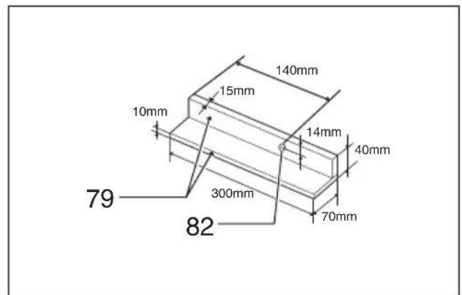
When securing aluminum extrusions, use spacer blocks or pieces of scrap as shown in the figure to prevent deformation of the aluminum. Use a cutting lubricant when cutting the aluminum extrusion to prevent build-up of the aluminum material on the blade.
CAUTION:
- Never attempt to cut thick or round aluminum extrusions. Thick aluminum extrusions may come loose during operation and round aluminum extrusions cannot be secured firmly with this tool.
- Never cut aluminum in the table saw mode (bench mode).
6. Wood facing
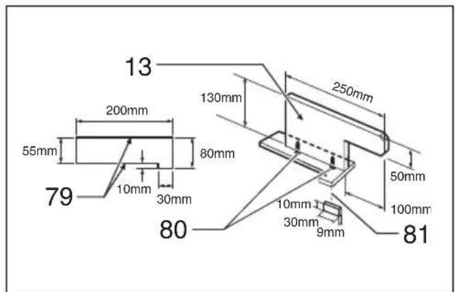
Use of wood facing helps to assure splinter-free cuts in workpieces. Attach a wood facing to the guide fence using the holes in the guide fence.
See the figure concerning the dimensions for a suggested wood facing.

005577
CAUTION:
- Use straight wood of even thickness as the wood facing.
- Use screws to attach the wood facing to the guide fence. The screws should be installed so that the screw heads are below the surface of the wood facing.
- When the wood facing is attached, do not turn the turn base with the handle lowered. The blade and/or the wood facing will be damaged.
7. Cutting repetitive lengths (Fig. 45)
When cutting several pieces of stock to the same length, ranging from 240mm to 400mm , use of the set plate will facilitate more efficient operation. Install the set plate on the holder as shown in the figure.
Align the cutting line on your workpiece with either the left or right side of the groove in the kerf board, and while holding the workpiece from moving, move the set plate flush against the end of the workpiece. Then secure the set plate with the screw. When the set plate is not used, loosen the screw and turn the set plate out of the way.
NOTE:
- Use of the holder-rod assembly (optional accessory) allows cutting repetitive lengths up to 2,200 mm approximately.
CUTTING AS TABLE SAW (BENCH MODE)
CAUTION:
- (For tools for European countries) When using the tool in the table saw mode (bench mode), flip the sub-fence outward and then take the following procedures.
When using the tool in the table saw mode (bench mode), (in case of tools for European countries, flip the sub-fence outward and) place the blade cover on the turn table so that the blade cover is centered over the slit for the blade entrance in the turn table and two small bosses on the underside of the blade cover fit into the semi-circular slit in the periphery of the turn table as shown in the figure and then lock the handle in the lowest position by fully pushing in the stopper pin. If not fixing the blade cover, the table can not be down. (Fig. 46)
CAUTION:
-
Always use "work helpers" such as push sticks and push blocks when there is a danger that your hands or fingers will come close to the blade.
-
Always hold the workpiece firmly with the table and the rip fence. Do not bend or twist it while feeding. If the workpiece is bent or twisted, dangerous kickbacks may occur.
- NEVER withdraw the workpiece while the blade is running. If you must withdraw the workpiece before completing a cut, first switch the tool off while holding the workpiece firmly. Wait until the blade has come to a complete stop before withdrawing the workpiece. Failure to do so may cause dangerous kickbacks.
- NEVER remove cut-off material while the blade is running.
NEVER place your hands or fingers in the path of the saw blade.
Always secure the rip fence firmly, or dangerous kickbacks may occur.
Always use "work helpers" such as push sticks and push blocks when cutting small or narrow workpieces.
Work helpers
Push sticks, push blocks or auxiliary fence are types of "work helpers". Use them to make safe, sure cuts without the need for the operator to contact the blade with any part of the body.
Push block (Fig. 47)
Use a 15 mm piece of plywood.
Handle should be in center of plywood piece. Fasten with glue and wood screws as shown. Small piece 10mm× 9mm× 30mm of wood must always be glued to plywood to keep the blade from dulling if the operator cuts into push block by mistake. (Never use nails in push block.)
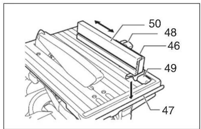
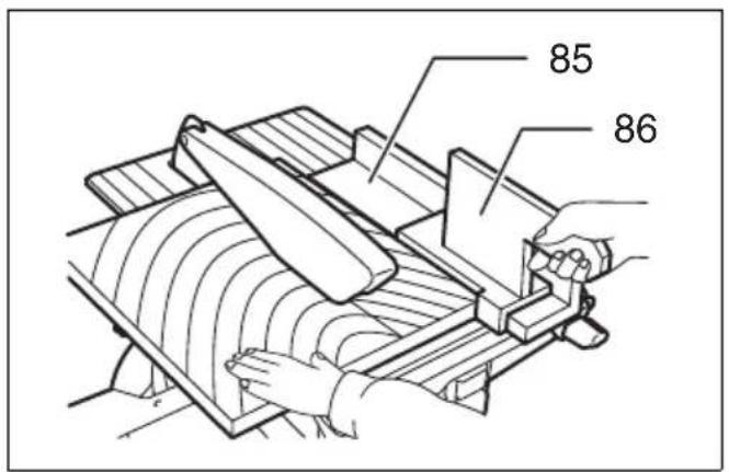
Auxiliary fence (Fig. 48 & 49)
Make auxiliary fence from 10mm and 15mm plywood pieces.
Remove the rip fence, clamping screw (A), flat washer and square nut from the rip fence holder and then attach and secure the auxiliary fence to the rip fence holder by using a bolt M6 longer than M6 x 50, washers and nut.
Ripping
CAUTION:
-
When cutting long or large workpieces, always provide adequate support behind the table. DO NOT allow a long board to move or shift on the table. This will cause the blade to bind and increase the possibility of kickback and personal injury. The support should be at the same height as the table.
-
Adjust the depth of cut a bit higher than the thickness of the workpiece. To make this adjustment, loosen two levers and lower or raise the top table.
-
Position the rip fence to the desired width of rip and secure in place by tightening the clamping screw (A). Before ripping, make sure the two screws of the rip fence holder are secured. If it is not secured enough, retighten it.
-
Turn the tool on and gently feed the workpiece into the blade along with the rip fence.
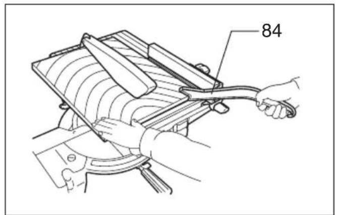
(1) When the width of rip is 40mm or wider, use a push stick. (Fig. 50)
(2) When the width of rip is narrower than 40~mm , the push stick cannot be used because the push stick will strike the top blade guard. Use the auxiliary fence and push block.
Install securely the auxiliary fence which is secured to the rip fence holder on the table. Feed the workpiece by hand until the end is about 25mm from the front edge of the top table. Continue to feed using the push block on the top of the auxiliary fence until the cut is complete. (Fig. 51)
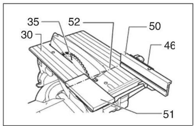
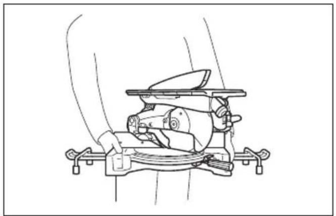
Carrying tool
Make sure that the tool is unplugged. Secure the blade at 0^ bevel angle and the turn base at left miter angle fully. Lower the handle fully and lock it in the lowered position by fully pushing in the stopper pin. (Fig. 52)
Carry the tool by holding both sides of the tool base as shown in the figure. If you remove the holders, dust bag, etc., you can carry the tool more easily. (Fig. 53)
CAUTION:
- Always secure all moving portions before carrying the tool.
MAINTENANCE
CAUTION:
- Always be sure that the tool is switched off and unplugged before attempting to perform inspection or maintenance.
- Never use gasoline, benzine, thinner, alcohol or the like. Discoloration, deformation or cracks may result.
WARNING:
- Always be sure that the blade is sharp and clean for the best and safest performance.
Adjusting the cutting angle
This tool is carefully adjusted and aligned at the factory, but rough handling may have affected the alignment. If your tool is not aligned properly, perform the following:
1. Miter angle
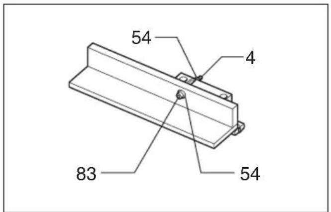
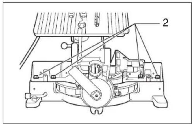
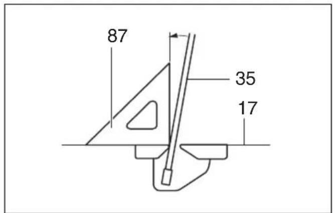
Loosen the grip which secures the turn base. Turn the turn base so that the pointer points to 0^ on the miter scale. Tighten the grip and loosen the hex bolts securing the guide fence using the socket wrench. (Fig. 54)
Lower the handle fully and lock it in the lowered position by pushing in the stopper pin. Square the side of the blade with the face of the guide fence using a triangular rule, try-square, etc. Then securely tighten the hex bolts on the guide fence in the order from the right side. (Fig. 55)
2. Bevel angle
(1) 0^ bevel angle
Lower the handle fully and lock it in the lowered position by pushing in the stopper pin. Loosen the lever at the rear of the tool.
Turn the 0^ bevel angle adjusting bolt on the right side of the turn base two or three revolutions clockwise to tilt the blade to the right. (Fig. 56)
Carefully square the side of the blade with the top surface of the turn base using the triangular rule, try-square, etc. by turning the 0^ bevel angle adjusting bolt counterclockwise. (Fig. 57)
Make sure that the pointer on the turn base point to 0^ on the bevel scale on the arm. If it does not point to 0^ , loosen the screw which secures the pointer and adjust the pointer so that it will point to 0^ . (Fig. 58)
(2) 45^ bevel angle
Adjust the 45^ bevel angle only after performing 0^ bevel angle adjustment. To adjust left 45^ bevel angle, loosen the lever and tilt the blade to the left fully. Make sure that the pointer on the arm points to 45^ on the bevel scale on the arm. If the pointer does not point to 45^ , turn the 45^ bevel angle adjusting bolt on the left side of the arm until the pointer points to 45^ . (Fig. 59)
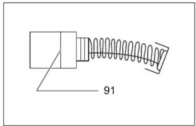
Replacing carbon brushes (Fig. 60 & 61)
Remove and check the carbon brushes regularly. Replace when they wear down to the limit mark. Keep the carbon brushes clean and free to slip in the holders. Both carbon brushes should be replaced at the same time. Use only identical carbon brushes.
Use a screwdriver to remove the brush holder caps. Take out the worn carbon brushes, insert the new ones and secure the brush holder caps.
After use
- After use, wipe off chips and dust adhering to the tool with a cloth or the like. Keep the blade guards clean according to the directions in the previously covered section titled "Blade guard". Lubricate the sliding portions with machine oil to prevent rust.
To maintain product SAFETY and RELIABILITY, repairs, any other maintenance or adjustment should be performed by Makita Authorized Service Centers, always using Makita replacement parts.
OPTIONAL ACCESSORIES
CAUTION:
- These accessories or attachments are recommended for use with your Makita tool specified in this manual. The use of any other accessories or attachments might present a risk of injury to persons. Only use accessory or attachment for its stated purpose.
If you need any assistance for more details regarding these accessories, ask your local Makita service center.
- Steel & Carbide-tipped saw blades
- Auxiliary plate
- Vise assembly (Horizontal vise)
Vertical vise - Socket wrench 13
- Holder set
- Holder assembly
- Holder rod assembly
- Set plate
Dust bag - Triangular rule
- Blade cover (Blade guard C)
- Push stick
Ruler assembly (Rip fence)
NOTE:
- Some items in the list may be included in the tool package as standard accessories. They may differ from country to country.
ENG905-1
Noise
The typical A-weighted noise level determined according to EN61029:
Sound pressure level (L_pA) : 93 dB (A)
Sound power level (L_WA) : 107 dB (A)
Uncertainty (K): 3 dB (A)
Wear ear protection
ENG900-1
Vibration
The vibration total value (tri-axial vector sum) determined according to EN61029:
Vibration emission (a_h):2.5m / s^2 or less
Uncertainty (K): 1.5m / s^2
ENG901-1
- The declared vibration emission value has been measured in accordance with the standard test method and may be used for comparing one tool with another.
- The declared vibration emission value may also be used in a preliminary assessment of exposure.
WARNING:
- The vibration emission during actual use of the power tool can differ from the declared emission value depending on the ways in which the tool is used.
- Be sure to identify safety measures to protect the operator that are based on an estimation of exposure in the actual conditions of use (taking account of all parts of the operating cycle such as the times when the tool is switched off and when it is running idle in addition to the trigger time).
EC DECLARATION OF CONFORMITY
For European countries only
The EC declaration of conformity is included as Annex A to this instruction manual.
Descriptif
ACCESSIONS EN OPTION
ATTENTION :
These Maschine woke up and went to the house. The man was a tall, tall man with a thick, dark face. He had been born in Germany, but he had never been born there. He had been born in Germany for many years, but he had never been born there.
1. Gehrungswinkel
OPTIONELE ACCESSOIRES
LET OP:
- Debido a un programa continuo de Investigación y descrollo, las specifications aquí dadas está sus-jetas a cam-bios sin previo aviso.
- Las specificationsSEOSEOSEOSEOSEOSEOSEOSEOSEOSEOSEOSEOSEOSEOSEOSEOSEOSEOSEOSEOSEOSEOSEOSEOSEOSEOSEOSEOSEOSEOSEOSEOSEOSEOSEOSEOSEOSEOSEOSEOSEOSEOSEOSEOSEOSEOSEOSEOSEOSEOSEOSEOSEOSEOSEOSEOSEOSEOSEOSEOSEOSEOSEOSEOSEOSEOSEOSEOSEOSEOSEOSEOSEOSEOSEOSEOSEOSEOSEOSEOSEOSEOSEOSEOSEOSEOSEOSEOSEOSEOSEOSEOSEOSEOSEOSEOSEOSEOSEOSEO SEO 01/2003