4329X - Electric saw MAKITA - Free user manual and instructions
Find the device manual for free 4329X MAKITA in PDF.
| Product Type | Electric Jigsaw |
| Brand | Makita |
| Model | 4329X |
| Stroke Length | 18 mm |
| Blade Type | Type B (T-shank) |
| Max. Cutting Capacity (wood) | 65 mm |
| Max. Cutting Capacity (mild steel) | 6 mm |
| Strokes per minute | 500 – 3 100 min⁻¹ (variable) |
| Overall Length | 223 mm (with aluminum base) |
| Net Weight | 1.9 kg (according to EPTA 01/2014) |
| Double Insulation | Yes (class II) |
| Power Supply | Single-phase mains, double insulation (no earthing required) |
| Cutting Modes | Straight cut (0), small orbit (I), medium orbit (II), large orbit (III) |
| Speed Adjustment | Adjustment dial (positions 1 to 6) |
| Bevel Cut | 0° to 45° (left and right) |
| Parallel Guide | Included (standard accessory) |
| Anti-splinter Device | Optional (for steel or aluminum base) |
| Dust Extractor Connection | Yes (hose supplied) |
| Sound Pressure Level (LpA) | 83 dB(A) (K=3 dB) |
| Sound Power Level (LWA) | 94 dB(A) (K=3 dB) |
| Vibration Emission (cutting boards) | 7.0 m/s² (K=1.5 m/s²) |
| Vibration Emission (cutting metal) | 5.0 m/s² (K=1.5 m/s²) |
| Maintenance | Regular cleaning, lubrication of the roller, replacement of carbon brushes by an authorized service center |
| Warranty | Consult the dealer or Makita after-sales service |
Frequently Asked Questions - 4329X MAKITA
User questions about 4329X MAKITA
0 question about this device. Answer the ones you know or ask your own.
Ask a new question about this device
Download the instructions for your Electric saw in PDF format for free! Find your manual 4329X - MAKITA and take your electronic device back in hand. On this page are published all the documents necessary for the use of your device. 4329X by MAKITA.
USER MANUAL 4329X MAKITA
GB Jig Saw Instruction Manual
natural_image
Line drawing of a J-shaped saw with a brand mark 'Makita' on the blade (no text or symbols beyond branding)

natural_image
Technical line drawing of a sewing machine needle and base (no text or symbols)1
2
3
4
5
6
7
8
9
natural_image
Line drawing of a sewing machine on a base, showing blade and foot positioning (no text or symbols)008087 008088 10
11 12
008089
008090
13 14
natural_image
Line drawing of a sewing machine on a cutting board, with part number 17 and decorative cutouts (no text or symbols)008091 008092
natural_image
Line drawing of a hand using a power tool to press or install a component on a flat surface (no text or symbols)15 16
natural_image
Line drawing of a hand operating a power tool on a flat surface (no text or symbols)008093 008094
17 18
008095
008096
19 20
008097
002776
21 22
005454
002777
23 24
005455
008098
25 26
008099 008100
008101
008102
27 28
Explanation of general view
| 1 Cutting action changing lever | 11 Retainer | 21 Aluminum base type |
| 2 Switch trigger | 12 Base | 22 Guide facing |
| 3 L o c k b u t t | 03 Dust cover | 23 Fence guide |
| 4 Speed adjusting dial | 14 Cutting line | 24 Threaded knob |
| 5 Blade holder | 15 Edge | 25 Pin |
| 6 B o l t | 16 Graduation | 26 Anti-splintering device |
| 7 H e x w r e n c | 17 Starting hole | 27 Protrusions |
| 8 Blade | 18 Hose | 28 Aluminum base |
| 9 R o l l e r | 19 Steel base type | 29 Cover plate |
| 10 Hook | 20 Rip fence (Guide rule) |
SPECIFICATIONS
| Model 4326 4327 | 4328 4329 | ||||
| Length of stroke 18 mm | 18 mm 18 mm 18 mm | ||||
| Blade type | B type | ||||
| Max. cutting capacities | Wood | 65 mm | 65 mm | 65 mm | 65 mm |
| Mild steel | 6 mm | 6 mm | 6 mm | 6 mm | |
| Strokes per minute (min ^-1 ) | 3,100 | 500 – 3,100 | 500 – 3,100 | 500 – 3,100 | |
| Overall length | 217 mm(Steel base type) | 217 mm(Steel base type) | 217 mm | 223 mm | |
| 223 mm(Aluminum base type) | 223 mm(Aluminum base type) | ||||
| Net weight | 1.9 kg | 1.9 kg | 1.8 kg | 1.9 kg | |
| Safety class | ☐/II | ||||
- Due to our continuing program of research and development, the specifications herein are subject to change without notice.
- Specifications may differ from country to country.
• Weight according to EPTA-Procedure 01/2014
ENE019-1
GEB186-1
Intended use
The tool is intended for the sawing of wood, plastic and metal materials. As a result of the extensive accessory and saw blade program, the tool can be used for many purposes and is very well suited for curved or circular cuts.
ENF002-2
Power supply
The tool should be connected only to a power supply of the same voltage as indicated on the nameplate, and can only be operated on single-phase AC supply. They are double-insulated and can, therefore, also be used from sockets without earth wire.
GEA010-2
General power tool safety warnings
⚠ WARNING Read all safety warnings, instructions, illustrations and specifications provided with this power tool. Failure to follow all instructions listed below may result in electric shock, fire and/or serious injury.
Save all warnings and instructions for future reference.
The term “power tool” in the warnings refers to your mains-operated (corded) power tool or battery-operated (cordless) power tool.
JIG SAW SAFETY WARNINGS
- Hold the power tool by insulated gripping surfaces, when performing an operation where the cutting accessory may contact hidden wiring or its own cord. Cutting accessory contacting a "live" wire may make exposed metal parts of the power tool "live" and could give the operator an electric shock.
- Use clamps or another practical way to secure and support the workpiece to a stable platform. Holding the workpiece by hand or against your body leaves it unstable and may lead to loss of control.
- Always use safety glasses or goggles. Ordinary eye or sun glasses are NOT safety glasses.
- Avoid cutting nails. Inspect workpiece for any nails and remove them before operation.
- Do not cut oversize workpiece.
- Check for the proper clearance beyond the workpiece before cutting so that the blade will not strike the floor, workbench, etc.
- Hold the tool firmly.
- Make sure the blade is not contacting the workpiece before the switch is turned on.
-
Keep hands away from moving parts.
-
Do not leave the tool running. Operate the tool only when hand-held.
- Always switch off and wait for the blade to come to a complete stop before removing the blade from the workpiece.
- Do not touch the blade or the workpiece immediately after operation; they may be extremely hot and could burn your skin.
- Do not operate the tool at no-load unnecessarily.
-
Some material contains chemicals which may be toxic. Take caution to prevent dust inhalation and skin contact. Follow material supplier safety data.
-
Always use the correct dust mask/respirator for the material and application you are working with.
SAVE THESE INSTRUCTIONS.
WARNING:
DO NOT let comfort or familiarity with product (gained from repeated use) replace strict adherence to safety rules for the subject product. MISUSE or failure to follow the safety rules stated in this instruction manual may cause serious personal injury.
FUNCTIONAL DESCRIPTION
CAUTION:
• Always be sure that the tool is switched off and unplugged before adjusting or checking function on the tool.
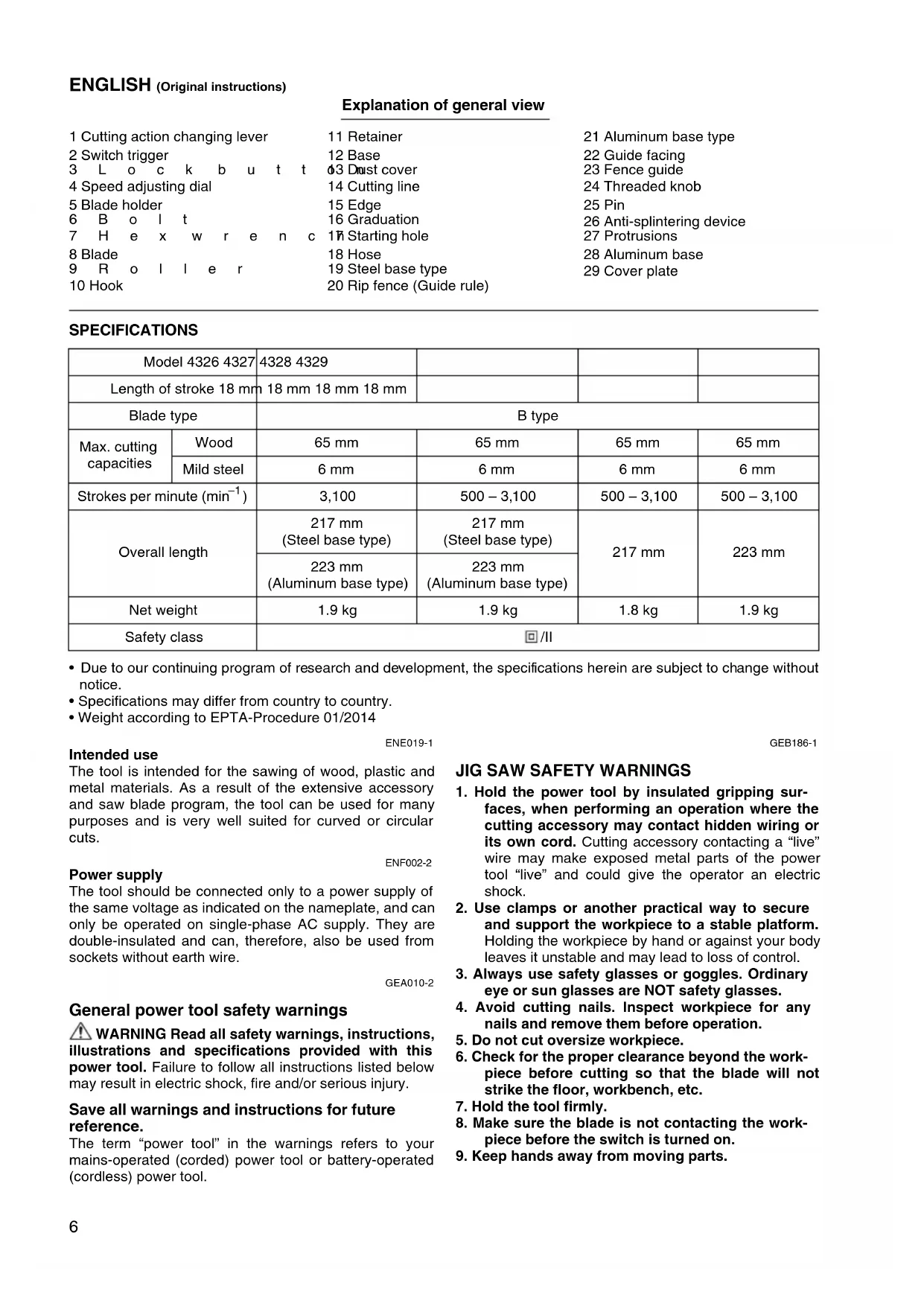
Selecting the cutting action (For models 4328/4329) (Fig. 1)
This tool can be operated with an orbital or a straight line (up and down) cutting action. The orbital cutting action thrusts the blade forward on the cutting stroke and greatly increases cutting speed.
To change the cutting action, just turn the cutting action changing lever to the desired cutting action position. Refer to the table to select the appropriate cutting action.
| Position Cutting action Applications | ||
| 0 Straight line cutting action | For cutting mild steel, stainless steel and plastics. | |
| For clean cuts in wood and plywood. | ||
| I Small orbit cutting action For cutting mild steel, aluminum and hard wood. | ||
| II Medium orbit cutting action | For cutting wood and plywood. | |
| For fast cutting in aluminum and mild steel. | ||
| III Large orbit cutting action For fast cutting in wood and plywood. | ||
006582
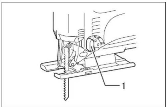
Switch action (Fig. 2)
CAUTION:
- Before plugging in the tool, always check to see that the switch trigger actuates properly and returns to the "OFF" position when released.
To start the tool, simply pull the switch trigger. Release the switch trigger to stop.
For continuous operation, pull the switch trigger and then push in the lock button.
To stop the tool from the locked position, pull the switch trigger fully, then release it.
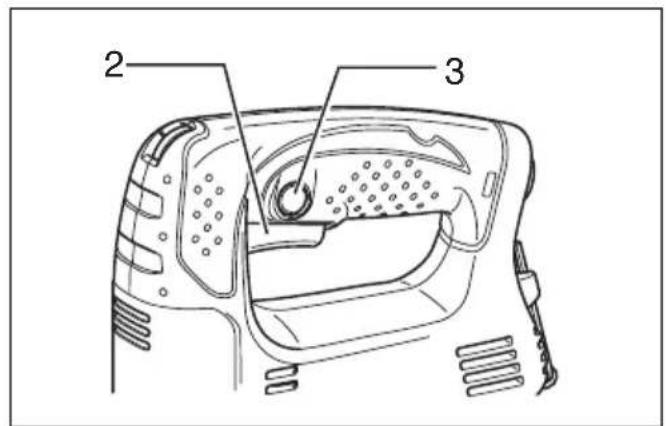
Speed adjusting dial (For models 4327/4328/4329) (Fig. 3)
The tool speed can be infinitely adjusted between 500 and 3,100 strokes per minute by turning the adjusting dial. Higher speed is obtained when the dial is turned in the direction of number 6; lower speed is obtained when it is turned in the direction of number 1.
Refer to the table to select the proper speed for the workpiece to be cut. However, the appropriate speed may differ with the type or thickness of the workpiece. In general, higher speeds will allow you to cut workpieces faster but the service life of the blade will be reduced.
| Workpiece to be cut N | Number on adjusting dial |
| Wood 5 – 6 | |
| Mild steel 3 – 6 | |
| Stainless steel 3 – 4 | |
| Aluminum | 3 – 6 |
| Plastics | 1 – 4 |
006583

CAUTION:
- If the tool is operated continuously at low speeds for a long time, the motor will get overloaded and heated up.
- The speed adjusting dial can be turned only as far as 6 and back to 1. Do not force it past 6 or 1, or the speed adjusting function may no longer work.
ASSEMBLY

CAUTION:
- Always be sure that the tool is switched off and unplugged before carrying out any work on the tool.
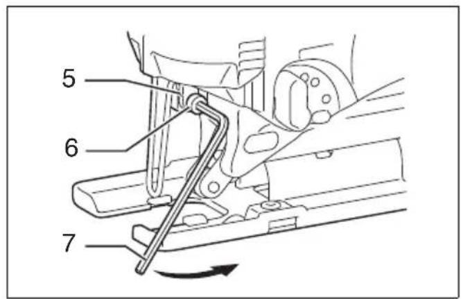
Installing or removing saw blade (Fig. 4 & 5)

CAUTION:
- Always clean out all chips or foreign matter adhering to the blade and/or blade holder. Failure to do so may cause insufficient tightening of the blade, resulting in a serious personal injury.
- Do not touch the blade or the workpiece immediately after operation; they may be extremely hot and could burn your skin.
- Always secure the blade firmly. Insufficient tightening of the blade may cause blade breakage or serious personal injury.
- Use only B type blades. Using blades other than B type blades causes insufficient tightening of the blade, resulting in a serious personal injury.
To install the blade, loosen the bolt counterclockwise on the blade holder with the hex wrench.
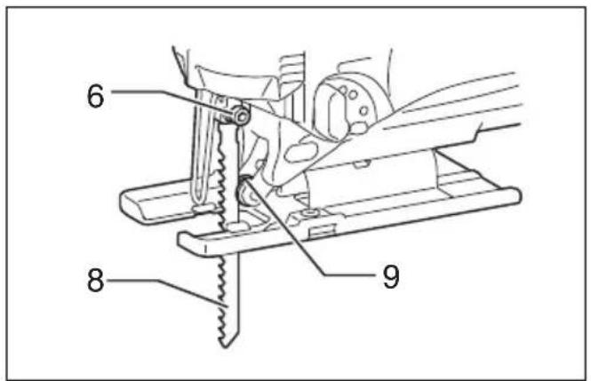
With the blade teeth facing forward, insert the blade into the blade holder as far as it will go. Make sure that the back edge of the blade fits into the roller. Then tighten the bolt clockwise to secure the blade.
To remove the blade, follow the installation procedure in reverse.
NOTE:
• Occasionally lubricate the roller.
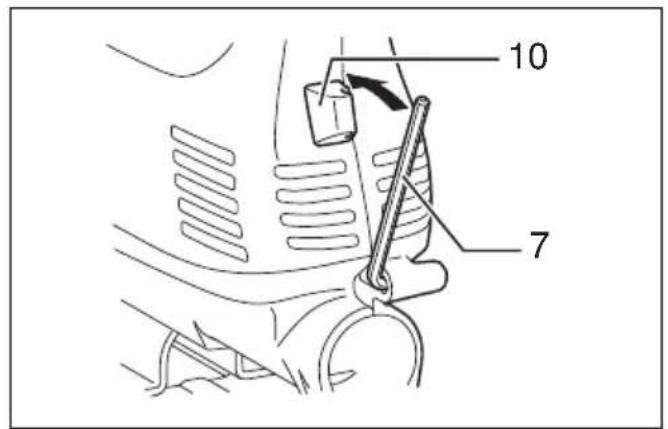
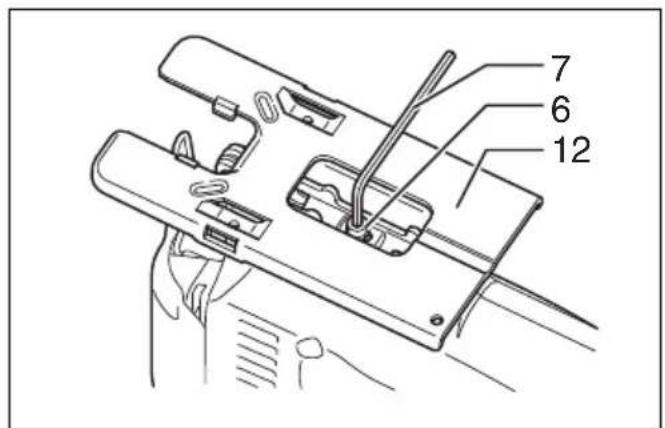
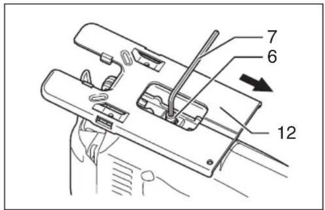
Hex wrench storage (Fig. 6)
When not in use, store the hex wrench as shown in the figure to keep it from being lost.
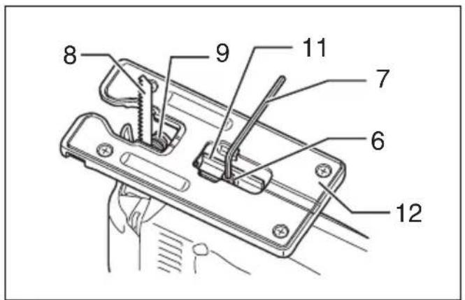
Adjusting roller (For models 4326/4327) (Fig. 7)
Loosen the bolt on the back of the tool base with the hex wrench. Move the retainer so that the roller contacts the blade lightly. Then tighten the bolt to secure the tool base and the retainer.
NOTE:
• Occasionally lubricate the roller.
Dust cover (Fig. 8)

CAUTION:
- Always wear safety goggles even when operating the tool with the dust cover lowered.
Lower the dust cover to prevent chips from flying. However, when making bevel cuts, raise it all the way.
OPERATION

CAUTION:
- Always hold the base flush with the workpiece. Failure to do so may cause blade breakage, resulting in a serious injury.
- Advance the tool very slowly when cutting curves or scrolling. Forcing the tool may cause a slanted cutting surface and blade breakage.
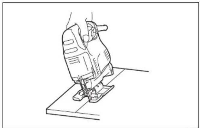
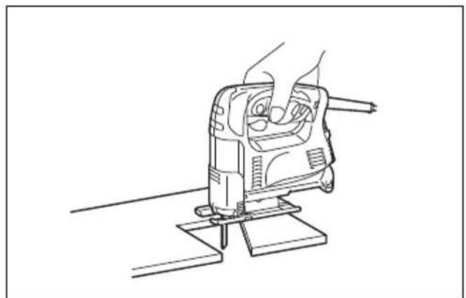
Turn the tool on without the blade making any contact and wait until the blade attains full speed. Then rest the tool base flat on the workpiece and gently move the tool forward along the previously marked cutting line. (Fig. 9)
Bevel cutting

CAUTION:
- Always be sure that the tool is switched off and unplugged before tilting the tool base.
- Raise the dust cover all the way before making bevel cuts.
With the base tilted, you can make bevel cuts at any angle between 0^ and 45^ (left or right). (Fig. 10)
Loosen the bolt on the back of the base with the hex wrench. Move the tool base so that the bolt is positioned in the center of the cross-shaped slot in the base. (Fig. 11)
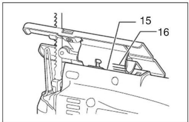
Tilt the base until the desired bevel angle is obtained. The edge of the motor housing indicates the bevel angle by graduations. Then tighten the bolt to secure the base. (Fig. 12)
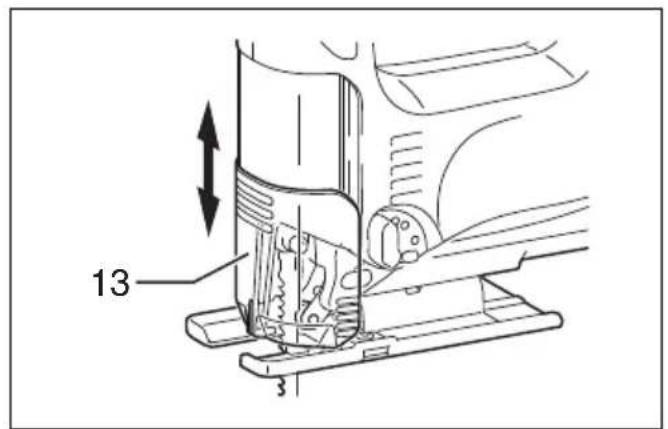
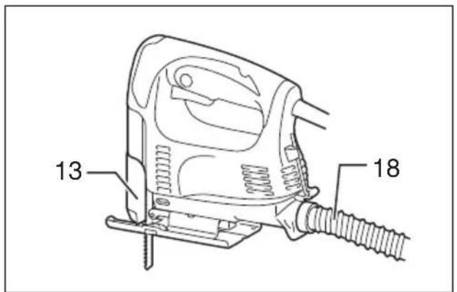
Front flush cuts (Fig. 13)
Loosen the bolt on the back of the tool base with the hex wrench, and slide the base all the way back. Then tighten the bolt to secure the tool base.
Cutouts
Cutouts can be made with either of two methods A or B.
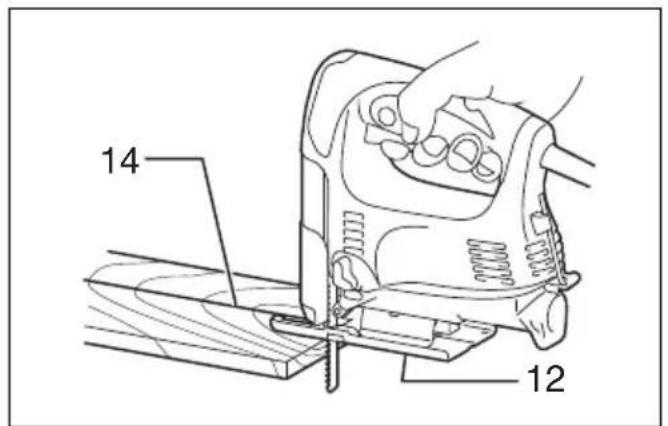
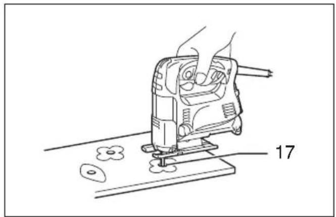
A) Boring a starting hole
For internal cutouts without a lead-in cut from an edge, pre-drill a starting hole 12 mm or more in diameter. Insert the blade into this hole to start your cut. (Fig. 14)
B) Plunge cutting
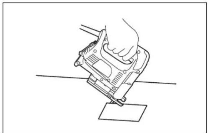
You need not bore a starting hole or make a lead-in cut if you carefully do as follows.
(1) Tilt the tool up on the front edge of the base with the blade point positioned just above the workpiece surface. (Fig. 15)
(2) Apply pressure to the tool so that the front edge of the base will not move when you switch on the tool and gently lower the back end of the tool slowly.
(3) As the blade pierces the workpiece, slowly lower the base of the tool down onto the workpiece surface.
(4) Complete the cut in the normal manner.
Finishing edges (Fig. 16)
To trim edges or make dimensional adjustments, run the blade lightly along the cut edges.
Metal cutting
Always use a suitable coolant (cutting oil) when cutting metal. Failure to do so will cause significant blade wear. The underside of the workpiece can be greased instead of using a coolant.
Dust extraction (Fig.17)
Clean cutting operations can be performed by connecting this tool to a Makita vacuum cleaner. Insert the hose of the vacuum cleaner into the hole at the rear of the tool. Lower the dust cover before operation.
NOTE:
- Dust extraction cannot be performed when making bevel cuts.
Rip fence (optional accessory)
CAUTION:
- Always be sure that the tool is switched off and unplugged before installing or removing accessories.
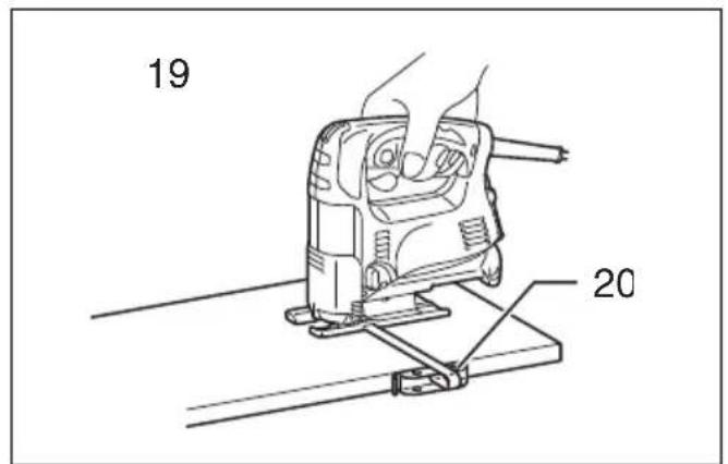
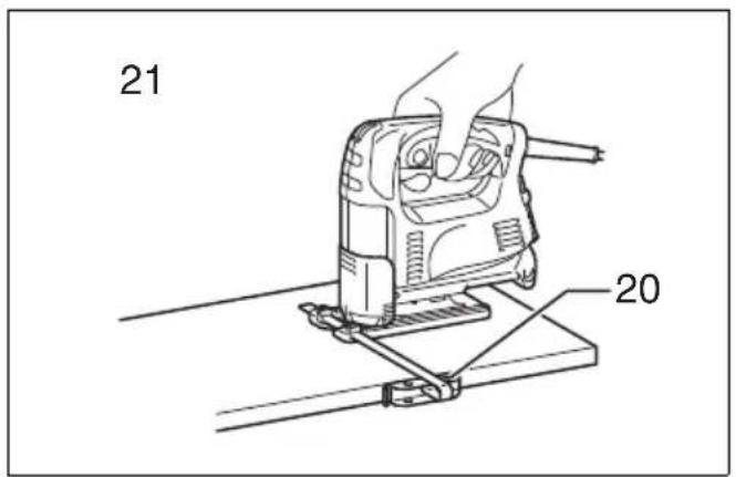
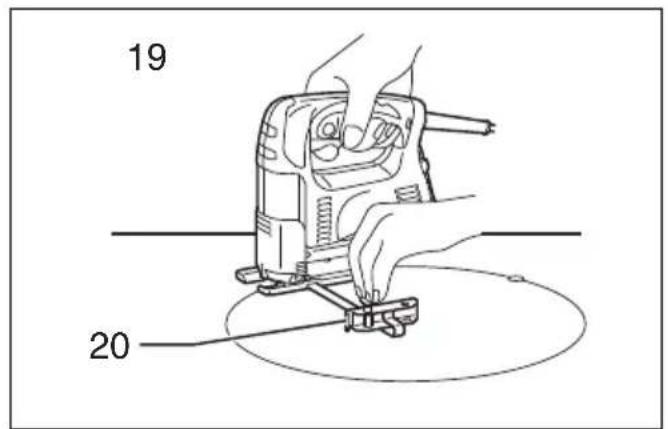
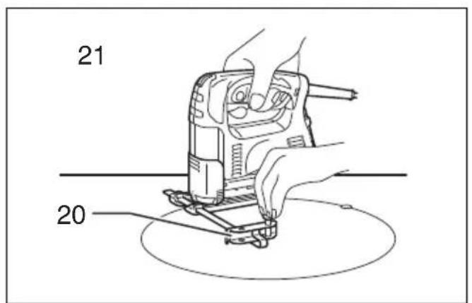
1. Straight cuts (Fig. 18, 19, 20 & 21)
When repeatedly cutting widths of 160 mm or less, use of the rip fence will assure fast, clean, straight cuts.
To install, insert the rip fence into the rectangular hole on the side of the base with the fence guide facing down. Slide the rip fence to the desired cutting width position, then tighten the bolt to secure it.
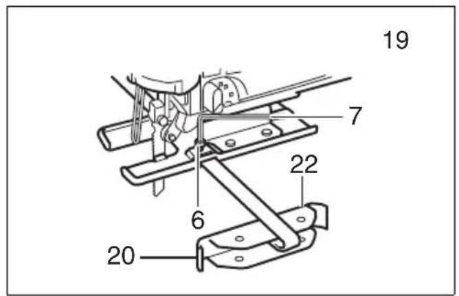
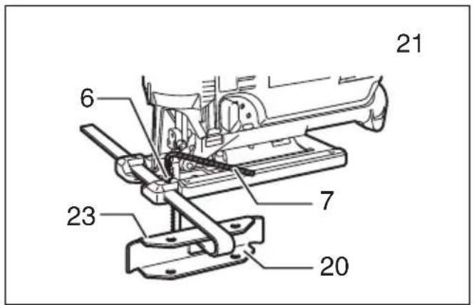
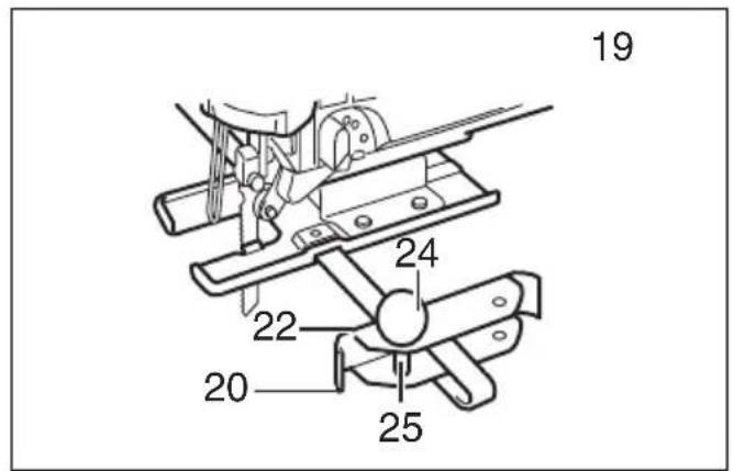
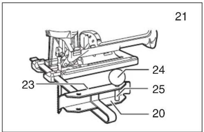
2. Circular cuts (Fig. 22, 23, 24 & 25)
When cutting circles or arcs of 170 mm or less in radius, install the rip fence as follows.
Insert the rip fence into the rectangular hole on the side of the base with the fence guide facing up. Insert the circular guide pin through either of the two holes on the fence guide. Screw the threaded knob onto the pin to secure the pin.
Now slide the rip fence to the desired cutting radius, and tighten the bolt to secure it in place. Then move the tool base all the way forward.
NOTE:
- Always use blades No. B-17, B-18, B-26 or B-27 when cutting circles or arcs.
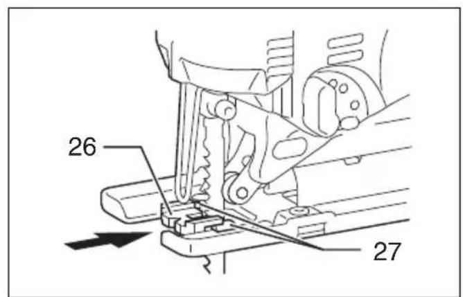
Anti-splintering device for steel base (optional accessory) (Fig. 26)
For splinter-free cuts, the anti-splintering device can be used. To install the anti-splintering device, move the base all the way forward and insert it between the two protrusions of the base.
NOTE:
- The anti-splintering device cannot be used when making bevel cuts.
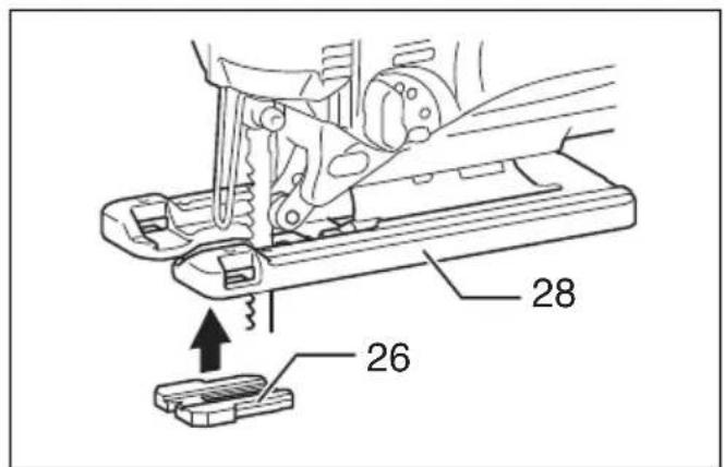
Anti-splintering device for aluminum base (optional accessory) (Fig. 27)
For splinter-free cuts, the anti-splintering device can be used. To install the anti-splintering device, move the tool base all the way forward and fit it from the back of tool base. When you use the cover plate, install the anti-splintering device onto the cover plate.
CAUTION:
- The anti-splintering device cannot be used when making bevel cuts.
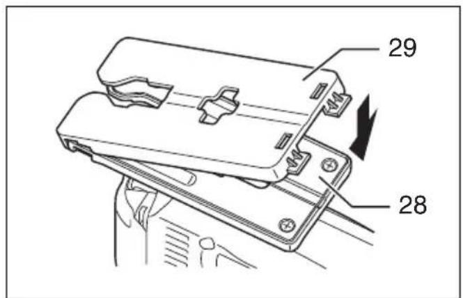
Cover plate for aluminum base (optional accessory) (Fig. 28)
Use the cover plate when cutting decorative veneers, plastics, etc. It protects sensitive or delicate surfaces from damage. Fit it on the back of the tool base.
MAINTENANCE
CAUTION:
- Always be sure that the tool is switched off and unplugged before attempting to perform inspection or maintenance.
- Never use gasoline, benzine, thinner, alcohol or the like. Discoloration, deformation or cracks may result.
To maintain product SAFETY and RELIABILITY, repairs, carbon brush inspection and replacement, any other maintenance or adjustment should be performed by Makita Authorized Service Centers, always using Makita replacement parts.
OPTIONAL ACCESSORIES
CAUTION:
- These accessories or attachments are recommended for use with your Makita tool specified in this manual. The use of any other accessories or attachments might present a risk of injury to persons. Only use accessory or attachment for its stated purpose.
If you need any assistance for more details regarding these accessories, ask your local Makita service center.
- Jig saw blades
- Hex wrench 3
- Rip fence (guide rule) set
• Anti-splintering device - Hose (For vacuum cleaner)
• Cover plate (For aluminum base type)
NOTE:
- Some items in the list may be included in the tool package as standard accessories. They may differ from country to country.
ENG905-1
Noise
The typical A-weighted noise level determined according to EN62841-2-11:
Model 4326, 4327
Sound pressure level ( L_pA ): 86 dB (A)
Sound power level ( L_WA ): 97 dB (A)
Uncertainty (K): 3 dB (A)
Model 4328, 4329
Sound pressure level ( L_pA ): 83 dB (A)
Sound power level ( L_WA ): 94 dB (A)
Uncertainty (K): 3 dB (A)
ENG907-1
NOTE:
- The declared noise emission value(s) has been measured in accordance with a standard test method and may be used for comparing one tool with another.
- The declared noise emission value(s) may also be used in a preliminary assessment of exposure.
WARNING:
- Wear ear protection.
- The noise emission during actual use of the power tool can differ from the declared value(s) depending on the ways in which the tool is used especially what kind of workpiece is processed.
- Be sure to identify safety measures to protect the operator that are based on an estimation of exposure in the actual conditions of use (taking account of all parts of the operating cycle such as the times when the tool is switched off and when it is running idle in addition to the trigger time).
Vibration
The vibration total value (tri-axial vector sum) determined according to EN62841-2-11:
Model 4326, 4327
Work mode: cutting boards
Vibration emission ( a_h,B ): 5.5 m/s ^2
Uncertainty (K): 1.5 m/s²
Work mode: cutting sheet metal
Vibration emission ( a_h,M ): 5.5 m/s ^2
Uncertainty (K): 1.5 m/s²
Model 4328, 4329
Work mode: cutting boards
Vibration emission ( a_h,B ): 7.0 m/s ^2
Uncertainty (K): 1.5 m/s²
Work mode: cutting sheet metal
Vibration emission ( a_h,M ): 5.0 m/s ^2
Uncertainty (K): 1.5 m/s²
ENG901-2
NOTE:
- The declared vibration total value(s) has been measured in accordance with a standard test method and may be used for comparing one tool with another.
- The declared vibration total value(s) may also be used in a preliminary assessment of exposure.

WARNING:
- The vibration emission during actual use of the power tool can differ from the declared value(s) depending on the ways in which the tool is used especially what kind of workpiece is processed.
- Be sure to identify safety measures to protect the operator that are based on an estimation of exposure in the actual conditions of use (taking account of all parts of the operating cycle such as the times when the tool is switched off and when it is running idle in addition to the trigger time).
EC DECLARATION OF CONFORMITY
For European countries only
The EC declaration of conformity is included as Annex A to this instruction manual.
Descriptif
DÉCLARATION DE CONFORMITÉ CE
Vibrationsemission ( a_h,M ): 5,0 m/s ^2
OPTIONELE ACCESSOIRES
LET OP:
Trillingsemissie ( a_h,M ): 5,0 m/s ^2
Onnauwkeurigheid (K): 1,5 m/s²
ENG901-2