
TVVR41210 - Voice recorder ABUS - Free user manual and instructions
Find the device manual for free TVVR41210 ABUS in PDF.
| Product type | 8-channel analog digital video recorder (DVR) |
| Brand | ABUS |
| Model | TVVR41210 |
| Dimensions (W x H x D) | 440 x 45 x 275 mm |
| Weight (without hard drive) | ≤ 4.0 kg |
| Power supply | 12 V DC, 5.0 A, 50~60 Hz |
| Power consumption (without hard drive) | < 15 W |
| Video compression | H.264 |
| Camera inputs | 8 BNC channels |
| Video outputs | 1 x BNC, 1 x VGA, 1 x HDMI |
| Maximum recording resolution | WD1 (704 x 576) at 25 fps per camera |
| Total frame rate | 200 fps |
| Internal storage | 2 x SATA 3.5" hard drives |
| USB ports | 2 x USB 2.0 (mouse, USB stick) |
| Network connectivity | 1 x RJ45 10/100 Mbps |
| Recording modes | Manual, scheduled, motion detection, alarm |
| Security functions | Motion detection, alarm, privacy zone, tamper-proof |
| Maintenance and cleaning | Clean with a damp cloth, do not use solvents |
| Spare parts and repairability | Standard SATA hard drives, remote control, USB mouse; repair by certified professional |
| Operating temperature | -10 °C to +55 °C |
| OSD languages | French, German, English, Dutch, etc. |
| Certifications | CE, RoHS |
Frequently Asked Questions - TVVR41210 ABUS
User questions about TVVR41210 ABUS
0 question about this device. Answer the ones you know or ask your own.
Ask a new question about this device
Download the instructions for your Voice recorder in PDF format for free! Find your manual TVVR41210 - ABUS and take your electronic device back in hand. On this page are published all the documents necessary for the use of your device. TVVR41210 by ABUS.
USER MANUAL TVVR41210 ABUS
ABUS 4/8/16-Kanal 650 TVL Realtime Digitalrekorder TVVR41200 / TVVR41210 / TVVR41220
Bedienungsanleitung
GB User guide
NL Gebruikershandleiding
PR Notice d'utilisation
DK Betjeningsvejledning
PL Instrukcja obslugi
RU Hnctpykunno 3Kcnnyataun
Version 1.0
CE
Deutsch
This user guide contains important information on starting operation and using the device.
Make sure that this user guide is handed over when the product is given to other persons.
Keep this user guide to consult later.
A list of contents with the corresponding page number can be found in the index.
Français
VGA-Monitor angeschlüssen
| BNC + VGA | HDMI only | VGA only | BNC only | BNC + VGA | HDMI + VGA |
| ✓ | ✓ | ✓ | ✓ | ✓ | ✓ |
Entsorgen
,Network Time Protokoll'
This user guide contains important information on starting operation and using the device.
Make sure that this user guide is handed over when the product is given to other persons.
Keep this user guide to consult later.
A list of contents with the corresponding page number can be found in the index..
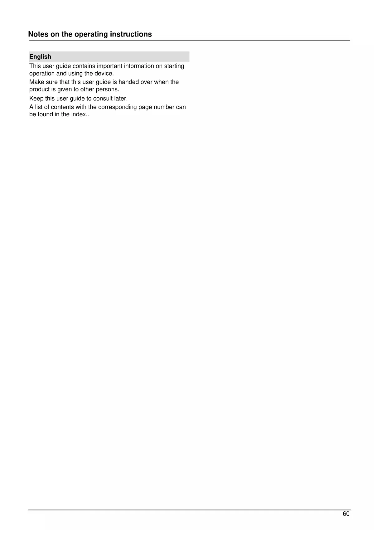
Device overview

See System operation on page 62.

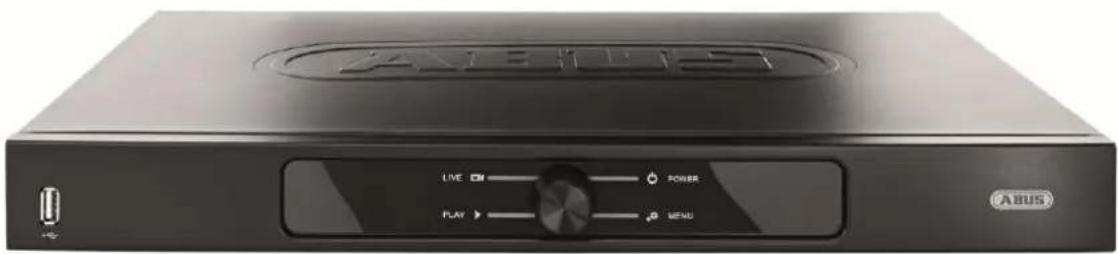
Rearside

Note
The illustrations for TVVR41200 and TVVR41210 are similar.
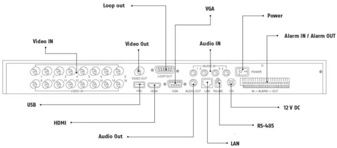
Front
System operation
General information
The device can be controlled as follows:
Using the USB mouse
Connections on the rear of the device

Note
Pay attention to the overview on page 61.
| Name Function |
| VIDEO IN: • BNC input for analogue cameras |
| VIDEO OUT: • Spot output |
| LOOP OUT: • Each camera input is looped here and output again |
| VGA: • VGA monitor connection (9-pin), video output signal |
| AUDIO IN: • Cinch inputs |
| POWER ON/OFF: On and off device switch |
| ALARM IN/OUT: • Max. 16 alarm inputs, max. 4 relay outputs |
| 12 V DC • 12 V DC connection for power supply |
| RS-485 • Connection for PTZ cameras |
| LAN • RJ45 port for a network connection |
| AUDIO OUT: • Cinch audio output (synchronised with the video output) |
| HDMI • HDMI monitor connection |
| USB • Connection for USB devices |
| SHUTTLE KNOB • For selecting the operating mode |
Mouse operation

Note
Further descriptions in these operating instructions are made with the mouse.
The device is suitable for use with a USB mouse.
Connect the mouse to the USB port.
| Button | Function |
| Left | Single-click:Selection in the menu, activation of an input field or a TAB, display of the Quick Set menuDouble-click:Switches between the screen display of single and multiple images in the live view and during playbackClick and drag:In PTZ mode: Camera controlSet-up of alarm areas or zones |
| Right | Single-click:Calls up the pop-up menu |
| Scroll wheel | In the live view:Shows previous / next cameraIn menus:Scrolls through the menus |
Device overview 61
System operation 62
General information 62
Connections on the rear of the device 62
Mouse operation 63
Quick guide 67
Before you start 67
Installing the HDD 67
Establishing the connections 67
Configuring the device 67
Important safety information 68
Explanation of symbols 68
Proper use 68
General information 68
Power supply 68
Overloading / overvoltage 69
Cables 69
Installation location / operating environment 69
Remote control. 69
Care and maintenance. 70
Accessories 70
Putting into operation 70
Children and the device 70
Introduction 71
General information 71
Unpacking the device. 71
Scope of delivery 71
On-screen keyboard 72
Starting the device 72
Switching off, locking and rebooting the device 72
Status displays. 73
General information 73
Display on the monitor 73
Setup wizard 74
Setting up the system 74
Setting up the administrator 74
Time / Date 74
Network Settings 75
HDD Management 75
Camera recording 75
Live view 76
Overview 76
Status symbols 76
76
Selection bar in the camera image 77
Settings 78
Setting the camera output 78
Playback 79
General information 79
Playback screen 79
Using the control panel. 79
Main menu 81
Menu overview 81
Menu description 81
Menu description 82
Configuration. 83
Overview. 83
General 83
Terms and definitions 84
Network layout 85
Network-configuration 85
Warning 89
User. 89
Camera 91
OSD 91
PTZ 91
Motion 92
Handling 92
Private Zone 93
Tamper monitoring 94
Video signal loss 94
Setting up 96
Schedule 96
Record 97
TAB Substream 97
Advanced settings 98
Holidays 98
HDDs 99
Installing the HDD 99
HDD Management parameters 99
HDD settings of the cameras 99
S.M.A.R.T. 100
Checking the HDD status. 100
Recording 101
Continuous Recording 102
Event 102
Video Export 103
Duration 103
Event (event type 'Motion') 104
Maintenance 105
System Info 105
Log Search. 105
Import/Export 106
Upgrade 106
Default 107
Network 107
Shutdown 109
Troubleshooting 110
Device cleaning and care 110
Contents
Note 110
Technical data 111
Disposal 113
Information on the EU directive on waste electrical and electronic equipment 113
Information on handling batteries 113
Important information on disposing of batteries. 113
Information on the European RoHS directive 113
Glossary 114
Overview of specialist terms 114
Internal HDD 116
Quick guide
Before you start
The following preparatory steps must be made:
- Pay attention to the general information, safety information and notes on setting up and connecting the device (see page 62).
- Check the contents of the package for completeness and damages.
- Insert the batteries into the remote control.

Note
Pay attention to the information in the separate quick guide.
Installing the HDD

Warning
Switch off the device and disconnect it from the mains power supply.
Pay attention to the required earthing of the device to avoid static discharge.
- Install one or more HDDs (see the separate quick guide).
- First make a connection to the motherboard (small connector).
- Connect the power supply cable (large 5-pin connector).
- Check that the connections are secure.
- Close the housing.

Note
Only use HDD's that are approved for video recording and 24/7 usage.
Establishing the connections

Note
Pay attention to the minimum radius when laying cables. Do not kink the cable.
- Connect all cameras to the recorder.
- Connect the monitor to the VGA, BNC- or HDMI connection.
- Connect the mouse to the USB port.
- Connect the device to the mains power supply, it will then start automatically.
Configuring the device

Note
Pay attention to the information in the separate quick guide.
- Proceed through the individual steps in the setup wizard (see page 74).
-
The following settings are configured in sequence:
-
Language selection for the user interface
- Administrator setup
- General settings (date, time etc.)
HDD management (initialisation etc.)
Network settings - Camera management

Note
Subsequent changes to the date and time can lead to the loss of data!

Note
Check the ABUS homepage (www.abus.com) if for this device any firmware updates are available and install these
- Pay attention to the menu overview on page 81, plus the notes and explanations on basic system operation on page.
Pay attention to the notes on the following:
| Live view | P. 76 |
| Playback | P. 79 |
| Data export | P. 102 |
| Troubleshooting | P. 109 |
Important safety information
Explanation of symbols
The following symbols are used in this manual and on the device:
Symbol Signal word Meaning

Warning
Indicates a risk of injury or health hazards.

Warning
Indicates a risk of injury or health hazards caused by electrical voltage.

Important
Indicates possible damage to the device/accessories.
Note
Indicates important information.
The following labels are used in the text:
| Meaning | |
| 1.... | Set of tasks or instructions with a defined sequence in the text |
| 2.... | |
| • ... | Set of points or warnings without a defined sequence in the text |
| • ... |
Proper use
Only use the device for the purpose which it was designed and built for. Any other use is considered inappropriate.
This device may only be used for the following purpose(s):
- This 4-channel/8-channel/16-channel analogue digital recorder is used in combination with connected video signal sources (analogue cameras) and video output devices (CRT or TFT monitors) for object surveillance.

Note
Data storage is subject to national data-protection guidelines.
During installation, inform your customers regarding the existence of these guidelines.
General information
Before using the device for the first time, read the following instructions carefully and pay attention to all warnings, even if you are already familiar with electronic devices.

Warning
All guarantee claims become invalid for damages caused by non-compliance with these operating instructions.
We cannot be held liable for resulting damages.

Warning
We cannot be held liable in the event of material or personal damage caused by improper operation or non-compliance with the safety information.
All guarantee claims are invalid in such cases.
Keep this manual in a safe place for future reference.
If you pass on or sell the device, you must also include this user manual.
This device has been manufactured in accordance with international safety standards.
Power supply
- Only operate this device through a power source which supplies the mains power specified on the type plate.
- If you are unsure of the power supply at the installation location, contact your power supply company.

Warning
Avoid data loss!
Always use an uninterruptible power supply (UPS) with overvoltage protection.
- Disconnect the device from the mains power supply before carrying out maintenance or installation work.
- The on/off switch does not completely disconnect the device from the mains power supply.
- To disconnect the device completely from the mains power supply, the plug must be disconnected from the mains socket. Therefore, the device should be positioned so that direct and unobstructed access to the mains socket is guaranteed at all times and the plug can be disconnected immediately in an emergency.
To avoid the possibility of fires, the plug should always be disconnected from the network socket if the device is not used for long periods. Disconnect the device from the mains power supply before impending electrical storms, or use an uninterruptible power supply.

Warning
Never open the device on your own! There is a risk of electric shocks!
If it is necessary to open the device, consult trained personnel or your local maintenance specialist.
- The installation or modification of a HDD should only be made by trained personnel or your local maintenance specialist.

Warning
The installation of additional equipment or modification of the device invalidates your guarantee if not carried out by trained personnel.
We recommend having the HDD installed by a maintenance specialist.
Your guarantee is invalidated in the event of improper installation of the HDD.
Overloading / overvoltage
- Avoid overloading of mains sockets, extension cables and adapters as this can result in fires or electric shocks.
- Use overvoltage protection to prevent damages caused by overvoltage (e.g. electrical storms).
Cables
- Always hold cables by the connector, and do not pull the cable itself.
- Never touch the mains cable with wet hands, as this can lead to a short circuit or electric shock.
- Never position the device, furniture or other heavy items on the cable. Ensure that the cable does not become kinked, especially on the connector and sockets.
- Never knot the cable, and do not tie it to other cables.
- All cables should be laid so that they cannot be stepped on or cause an obstruction.
- A damaged mains cable can cause a fire or electric shock. Check the mains cable from time to time.
- Never modify or manipulate the mains cable or plug.
- Do not use plug adapters or extension cables that do not conform to the applicable safety standards, and do not make alterations to power supply cables or mains cables.
Installation location / operating environment
- Position the device on a firm, level surface and do not place any heavy objects on the device.
- The device is not designed for operation in rooms subject to high temperatures or moisture (e.g. bathrooms), or in excessively dusty rooms.
- Operating temperature and ambient humidity: -10 °C to 55 °C, maximum 85% relative humidity. The device may only be operated in moderate climate conditions.
Ensure the following:
- Sufficient ventilation must be present at all times (do not place the device in a storage rack, on thick carpets, on a bed or anywhere where the ventilation slots are covered. Make sure that a gap of at least 10cm is present on all sides).
- The device must not be exposed to direct heat sources (e.g. heaters).
- The device must not be exposed to direct sunlight or strong artificial light.
- The device must not be placed in close proximity to magnetic fields (e.g. loudspeakers).
- Naked flames (e.g. candles) must not be placed on or near the device.
- Contact with spraying or dripping water and aggressive liquids must be avoided.
- The device must not be operated in close proximity to water, and must not be submerged under any circumstances (do not place objects containing water on or near the device, such as vases or drinks).
Foreign objects must not penetrate the device. - The device must not be exposed to strong variations in temperature, as this can lead to condensation and electrical short circuits.
- The device must not be exposed to excessive jolts or vibrations.
Remote control
- Remove all batteries if the device will not be used for a sustained period, as these can leak and damage the device.
Care and maintenance
Maintenance is necessary if the device has been damaged. This includes damage to the plug, mains cable and housing, penetration of the interior by liquids or foreign objects, exposure to rain or moisture or when the device does not work properly or has fallen.
- Disconnect the device from the mains power supply before maintenance (e.g. cleaning).
- If smoke develops or unusual noises or odours are detected, then switch off the device immediately and pull the mains plug from the socket. In such cases, the device should not be used until it has been inspected by a qualified technician.
- Maintenance work should only be carried out by qualified specialists.
- Never open the housing on the device or accessories. There is a risk of fatal injury due to an electric shock when the housing is opened.
- Clean the device housing and remote control with a damp cloth.
- Do not use solvents, white spirit or thinners as these can damage the surface of the device.
- Do not use any of the following substances:
Salt water, insecticides, solvents containing chlorine or acids (ammonium chloride) or scouring powder. - Gently rub the surface with a cotton cloth until it is completely dry.

Warning
The device works under dangerous voltages. The device must only be opened by authorised speciaIstists. All maintenance and service work must be carried out by authorised firms. Improper repairs can expose device users to the risk of fatal injury.
Accessories
- Only connect devices that are suitable for the intended purpose. Otherwise, hazardous situations or damage to the device can occur.
Putting into operation
- Observe all safety and operating instructions before putting the device into operation for the first time.
- Only open the housing to install the HDD.

Warning
When installing the device in an existing video surveillance system, ensure that all devices are disconnected from the mains power supply and low-voltage circuit.

Warning
If in doubt, have a specialist technician carry out assembly, installation and connection of the device.
Improper or unprofessional work on the mains power supply or domestic installation puts both you and other persons at risk.
Connect the installations so that the mains power circuit and low-voltage circuit always run separately from each other. They should not be connected at any point or become connected as a result of a malfunction.
Children and the device
- Do not allow children access to electrical devices. Never allow children to use electrical devices without supervision. Children may not be able to accurately detect possible risks. Small parts can be life-threatening if swallowed.
- Keep batteries away from small children. Call for medical assistance immediately if a battery is swallowed.
- Keep packaging materials away from children (danger of suffocation).
- This device should not be used by children. If used improperly, spring-loaded parts can be ejected and cause injuries to children (e.g. eye injuries).
Introduction
Dear customers,
This device complies with the requirements of the applicable EU directives.
The declaration of conformity can be ordered from:
To maintain this status and to guarantee safe operation, it is your obligation to observe these operating instructions!
Read the entire operating manual carefully before putting the product into operation and pay attention to all operating and safety information!
All company names and product descriptions are trademarks of the corresponding owner. All rights reserved.
In the event of questions, please contact your local maintenance specialist or dealer.

Disclaimer
These operating instructions have been produced with the greatest care. Should you discover any missing information or inaccuracies, please contact us under the address shown on the back of the manual. ABUS Security-Center GmbH does not accept any liability for technical and typographical errors, and reserves the right to make changes to the product and operating instructions at any time and without prior warning. ABUS Security-Center GmbH is not liable or responsible for direct or indirect damages resulting from the equipment, performance and use of this product. No forms of guarantee are accepted for the contents of this document.
General information
In order to use the device correctly, read this user manual carefully and keep it in a safe place for later use.
This manual contains instructions on recorder operation and maintenance. Consult an authorised specialist if the device needs to be repaired.
Unpacking the device
Handle the device with extreme care when unpacking it.
The packaging is made of reusable materials, and should always be passed on for recycling.
We recommend the following:
Paper, plastic packaging, cardboard and corrugated cardboard should be disposed of in the appropriate recycling containers.
If recycling containers are not available in your local area, then you can dispose of these materials as domestic waste.
If the original packaging has been damaged, inspect the device. If the device shows signs of damage, then return it in the original packaging and contact the manufacturer.
Scope of delivery
- ABUS 4-channel/8-channel/16-channel analogue digital recorder
Power supply unit - 3x power cable (DE, UK, AU)
- SATA cable and screws for hard drive(s)
- Bracket and screws for server cabinet
- USB mouse
- Quick guide
- Manual
CD
On-screen keyboard
The on-screen keyboard appears after clicking on a text entry field with the mouse:

The following screen keyboard appears during mere numerical entry:

The keys have the same function as on a computer keyboard.
To enter the character, left-click the mouse.
- To finish data entry, press Enter.
To delete the character in front of the cursor, click on
- To switch between upper and lower case, click on the framed a symbol. The current setting is displayed above the keyboard.
- To cancel the entry or exit the field, press ESC.
Starting the device

Important
The device must only be operated with the mains power specified on the type plate.
For safety reasons, use an uninterrupted power supply (UPS).
When the device is connected to the power supply, it starts up automatically.
- The device carries out a self-test during the start-up procedure.
- The setup wizard appears. Exit the wizard to access the live view.
Switching off, locking and rebooting the device
Click on "Shutdown" in the main menu. The overview appears.
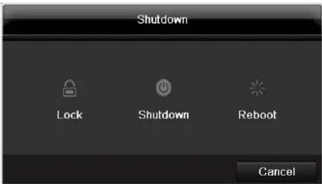
-
To switch off the device, select Shutdown and confirm by pressing Yes. The device is then switched off.
-
Do not press any keys during the shutdown procedure.
-
Now pull out the plug of the power supply unit.
-
To lock the system, select the corresponding Lock symbol on the left. The user interface is now locked and a password must be entered to access the menu.
- To reboot the device, select the corresponding Reboot symbol on the right. The device is then rebooted.
Switching on the device
- Plug in the power supply unit to start the device.
Status displays
General information
The following status displays indicate the current operating state:
- LEDs on the front of the device
- Acoustic signal tones
- Icons (display elements) on the monitor
i Note
Pay attention to the information in the separate quick guide.
Display on the monitor
The device shows the date and time, camera name and whether a recording is in progress.
- Continuous recording: blue "R"
- Motion detection recording yellow "R"
Setup wizard
Setting up the system
The setup wizard guides you through the necessary basic system settings. The DVR is then set up for recording and surveillance.

Note
All detailed settings can be found in the device menu (see overview on 81).
The language selection appears after switching on for the first time:
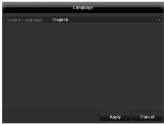
- Click the entry field and select the desired language from the list. Click on Apply to continue. The following query appears:
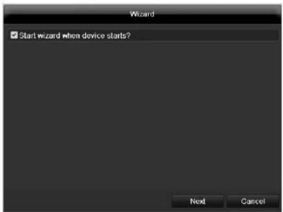
- Click on Next to start the wizard.

Note
After the system is set up, you can untick the box. The setup wizard is then no longer started automatically.
Setting up the administrator

Warning
Note down the admin password. The following password is preset
"12345"
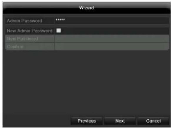
- Click the entry field and enter your admin password.
- To assign a new password, tick the box next to New Admin Password.
- Enter the new password and confirm in the field below.
- Click on Next.
Time / Date
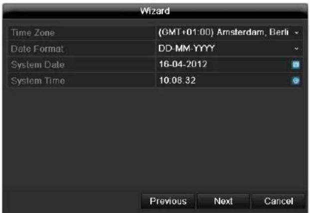
Enter the system time (date and time). Click on Next to accept the data.
Network Settings
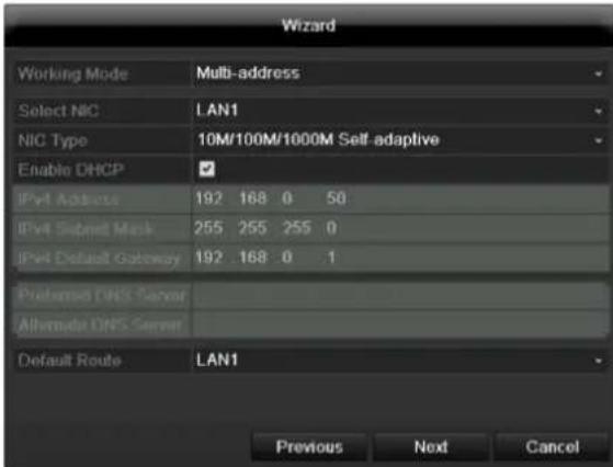

Note
To check whether DHCP can be selected (or if you have to set the IP address and other settings manually), consult your network administrator.
- DHCP activated: If DHCP is set up in the network router, then tick the DHCP box. All network settings are then made automatically.
- DHCP not activated: Enter the data manually (IPv4 address, IPv4 subnet mask and IPv4default gateway = IPv4 address of the router). You can also optionally enter the address of the DNS server that you need for sending the E-mail.
A typical address specification is as follows:
IPv4 address: 192.168.0.50
IPv4 Subnet mask: 255.255.255.0
IPv4 Default gateway: 192.168.0.1
Preferred DNS server: 192.168.0.1

Note
When the device is accessed remotely via the internet, it should be given a fixed network address.
HDD Management
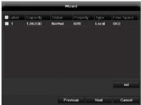
- To set up a new hard disc, activate the "Check box" with a left click and then click on Init.

Warning
All data on the drive is deleted!
- Confirm the prompt by pressing OK. The HDD is then set up for operation. The progress is displayed on the status bar.
- Exit the setting by pressing Next.
Camera recording
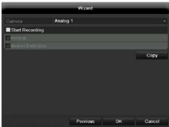
- At "Camera" select a camera with which you would like to record.
- Activate the check box "Start recording".
- Select the type of recording. You can choose between "Time plan" and "Motion recognition". Arm the motion detection inside the camera for recording motion.
- Press Copy to take on the setting for other cameras. For this, select the cameras that appear in the new window. Activate the respective check box with a mouse click.
- Finalize the setting and end the installation assistant with OK.
Live view
Overview
The live view starts automatically after the device is switched on.
You can also go back to the live view by pressing the Menu key repeatedly.
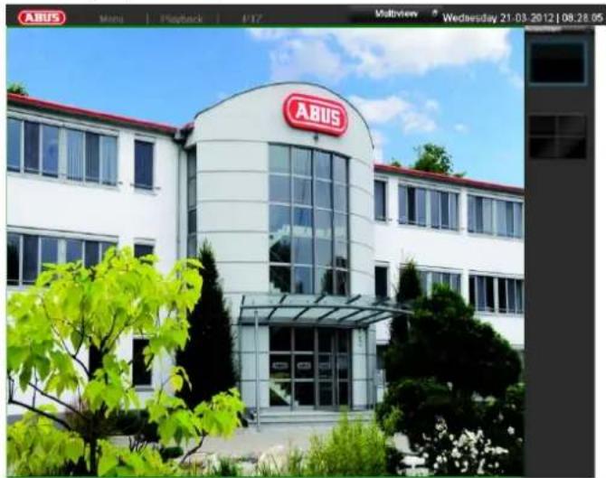
The following menus are found in the screen header:
- Menu
- Playback
- PTZ
The view pop-up menu is found on the right. The time and date are displayed on the right.
- Click on the symbol to open the pop-up menu of the multi view.
- Click on one of the symbols to switch between the different views.


The signals of the connected cameras are displayed on the main screen.
- By double-clicking the left mouse key, you can display the camera image as a full-screen view or switch back to the original view.
Status symbols
The following symbols are displayed depending on the operating status of the device:
| Symbol | Meaning |
| R | Yellow: Motion Recording • Recording at motion detection |
| R | Blue: Recording • Continuous recording |
Pop-up menu for mouse operation
i
Note
Press the right mouse button when the cursor is positioned on a live image.
The following settings can be made. The arrow pointing to the right indicates that a sub-menu is opened for selection:
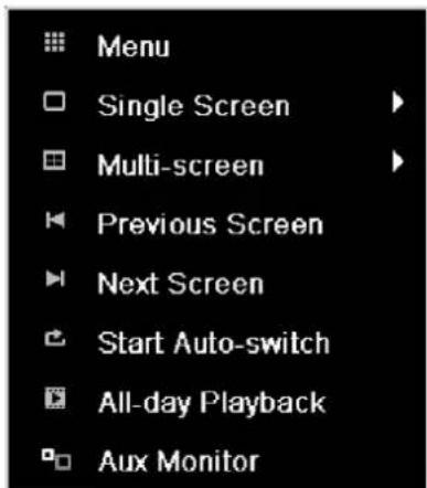
| Menu | Opens the main menu |
| Single Screen | Full-screen view for selected camera |
| Multi Screen | Various camera layouts |
| Previous Screen | Changing the presentation of the previous camera |
| Next Screen | Displays the next camera(s) |
| Start Auto-Switch | Starts the camera sequence |
| Start Recording | Starts motion detection or the schedule for the entire day |
| Quick Set | Setting for the output mode |
| All-day playback | Switches to playback mode |

Note
Stop Auto-switch:
Specify the delay in the image sequence in the display settings.
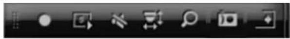
Selection bar in the camera image
Click on the camera image in single or multi view. A selection bar appears:
(1) (2)
(2)
(3)
(
(7)
(8)
| No. | Meaning/function |
| (1) | Area for moving the miniature bar |
| (2) | Activate/deactivate manual recording |
| (3) | Instant playback of the last 5 minutes |
| (4) | Audio |
| (5) | PTZ menu |
| (6) | Digital zoom |
| (7) | Image settings |
| (8) | Close the selection list |
Settings

Note
The live view can be set as follows.
Open the main menu, then click on "Configuration". Then click on "Liveview":
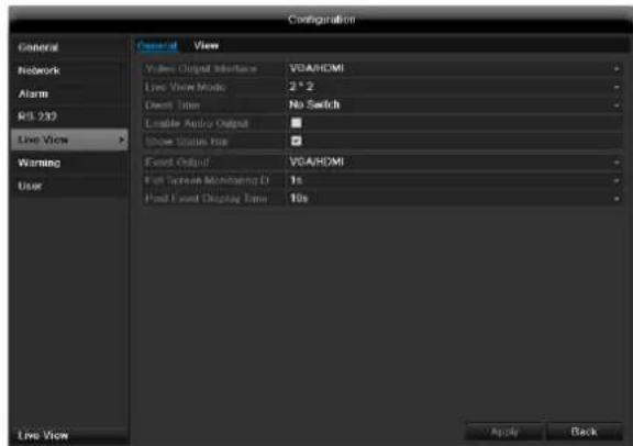
The following settings are available in the TAB "General":
| Video Output Interface | VGA/HDMI, Main CVBS Select the connection where the set-tings are changed |
| Live View Mode | Different camera layouts |
| Dwell Time | Switching time between the individu-al cameras and the sequence dis-play |
| Audio | Activate audio |
| Display status bar | Activate/deactivate the status bar |
| Event Output | Allocate monitor for the output of events |
| Full Screen Monitoring Duration | in seconds, where the event on the allocated monitor will be displayed. |
| Post Event Dis-play Time | in seconds, the duration of the Pop-up window when an event occurs. |

Note VGA monitor connected:
A connected VGA monitor automatically becomes the main monitor where the audio output is also assigned.
No HDMI monitor connected
If during the boot process of the DVR the HDMI cable is not connected, the main video signal is displayed at VGA output. Connect the HDMI cable and reboot the DVR in order to display the main video signal at the HDMI output.
Setting the camera output
You can display a maximum of 16 cameras simultaneously in the live view.
- Click on the TAB "View".
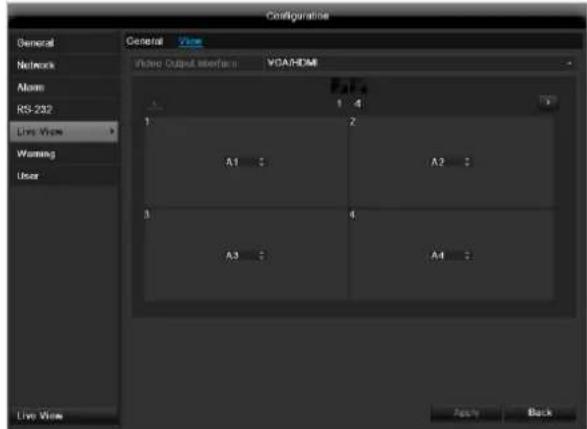
- Select the display mode (depends on the model)
1x1
2× 2
-1+5
-1+7
-3x3
4× 4
-
The camera signal is assigned to the corresponding image section using the navigation keys.
-
"X" means that this camera is not displayed.
-
Click on Apply to accept the settings.
Playback
General information
Playback can be made in three different ways:
- Through the video search in the main menu
From the live view - Through the log file in the maintenance menu

Note
The buttons "previous file/day/event" are used differently depending on the playback mode:
Normal playback:
By pressing the button the playback jumps to the previous/next day.
Video Search:
By pressing the button the playback jumps to the previous/next event day.
Video Export:
By pressing the button the playback jumps to the previous/next file.

Note
It is possible to start a simultaneous playback with up to 4 cameras.
Playback screen
Playback is controlled on the control panel:
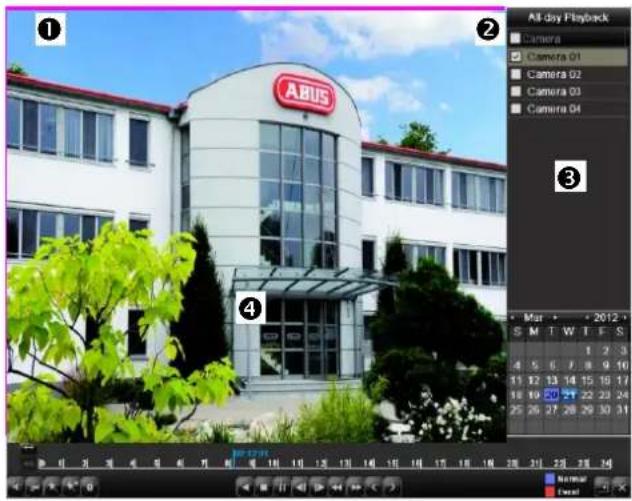
| No. | Area |
| 1 | Running playback with date and time |
| 2 | Used to select the camera for feedback |
| 3 | Calendar with recording type |
| 4 | Control panel with time bar (see right) |
Using the control panel
The control panel (4) is used for controlling the running playback. The symbols have the following meaning:
(1)

(2) (3) (4) (5) (6)

(7) (8) (9) (10)(11)(12)(13)(14)(15)

(17) (18) (19)
| No. | Meaning / function |
| 1 | Start video clip |
| 2 | Add marking |
| 3 | Add user-defined marking |
| 4 | Manage markings |
| 7 | Backwards playback |
| 8 | Stop |
| 9 | Playback start / pause |
| 10 | Jump backward 30 seconds |
| 11 | Jump forward 30 seconds |
| 12 | Slow forward (slow motion) (1/16x - 1x) |
| 13 | Fast forward (1x - 16x) |
| 14 | Previous recording marking |
| 15 | Next marking |
| 16 | Time bar:Click on the time bar with the mouse to continu-ue playback from another pointTo start playback from a specific time, click on the slider and drag it to the required time |
| 17 | Recording typeBlue = Continuous recordingRed = Event recordingGreen = Smart |
| 18 | Hides the control panel |
| 19 | Exits playback |
Please klick on ,Tag management' (6):
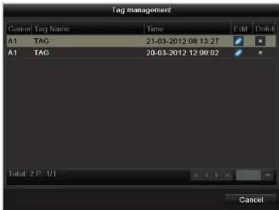
- In order to change the description of your marking, click on the process symbol. To remove, click on the delete symbol.
Main menu
Menu overview
The following overview shows the main menus used to set and control the device.
Furthermore you can find important information regarding the devide on the right side of the menu.
- Click on the menu to open it.
- Click Exit to close the menu overview.
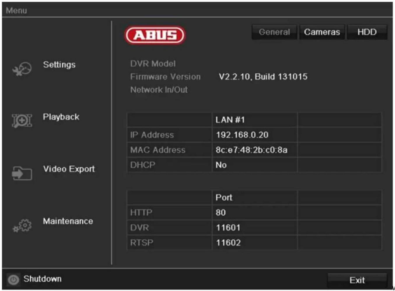
Menu description
| Menu | Description | See page... |
| Settings | Includes the menus Configuration, Camera, Record, HDD, Playback. | 90 |
| Playback | Parameter-controlled search for video and image recordings which were triggered by events such as motion detection, as well as markings set in playback. | 101 |
| Video Export | Parameter-controlled search for video and image recordings which were triggered by events such as alarms or motion detection, as well as alarm events and markings set in playback. | 102 |
| Maintenance | System information, searching logs, importing/exporting configurations, device maintenance such as updating new firmware, loading factory settings, displaying network loads. | 104 |
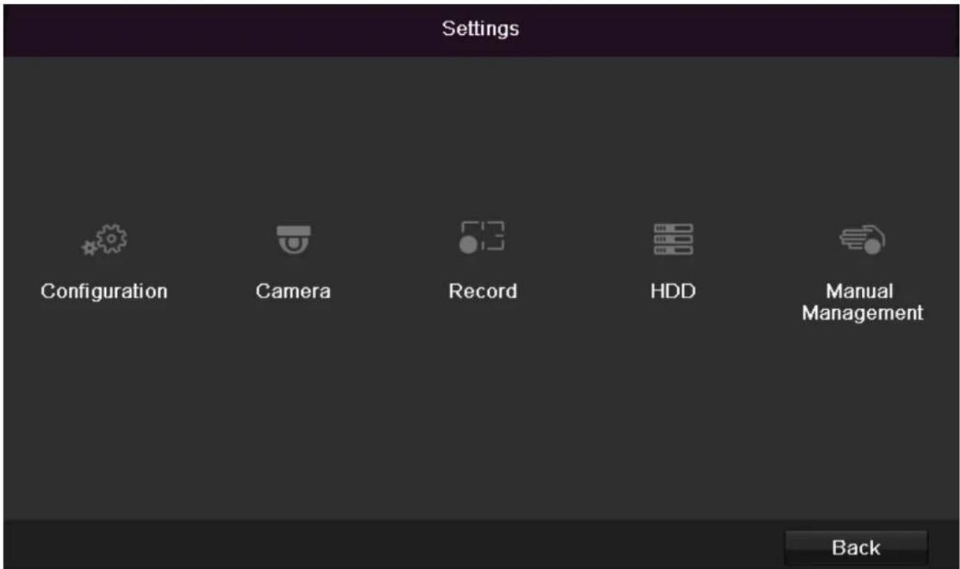
Menu description
| Menu | description | page |
| Configuration | Used for managing all device settings (General, Network, Live View, Exception, User). | 82 |
| Camera | Menu for setting camera parameters (OSD configuration, image mode, motion recognition, Private Zone, Tamper Monitoring, Video Loss). | 91 |
| Record | Menu to set recording parameters (time plan, camera resolution, camera stream etc.). | 96 |
| HDD | Used for initialising or managing installed HDD (assigning read/write functions, cameras, network HDD management etc.). | 99 |
| Manual Management | Menu for setting manual recordings. | 102 |
Configuration

Note
The "Configuration" menu is used to manage all device settings.

Warning
Ensure that the date and time are set correctly.
IMPORTANT:
Subsequent changes to the settings can lead to data loss!
Ensure a data backup has been made in good time beforehand.
Overview
| Menu | Setting | Page |
| General | Language, video, time, date, mouse pointer, password, time zones and other settings | 83 |
| Network | Required network settings (manual IP, DHCP, PPPOE, DDNS etc.) | 85 |
| Alarm | Settings for the alarms | xx |
| Live View | Display settings and assign-ment of the event output | 63 |
| Warning | Behaviour of the device in exceptional cases (HDD full, network disconnect-ed etc.) | 89 |
| User | Adding and changing users, assigning authorisation rights | 89 |

Note
Pay attention to the instructions in the correspond
ing sections.
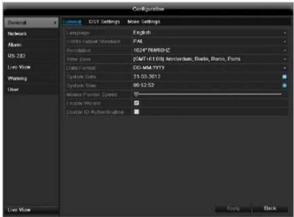
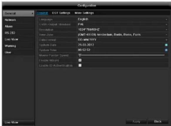
General
| “General” tab | Setting |
| Language | Language on the OSD |
| Resolution | Resolution on the monitor |
| Time Zone | GMT (Greenwich Mean Time) |
| Date Format | MM-DD-YYYY, DD-MM-YYYY, YYYY-MM-DD |
| System Da- te/Time | Date and time |
| Mouse Pointer Speed | Set on the scroll bar (left = low speed; right = high speed) |
| Enable Wizard | Box ticked: Wizard will appear after restart of the device. |
| Enable ID Authentication | Box not ticked: In order to enter a menu no password has to be entered. At access by net- work the password has to be entered. Box ticked: Password must be entered in order to use the menu. |
| TAB “DST set-tings” | Setting |
| Auto DST Adjustment | With an activated check box, the device converts automatically to summer time. |
| Enable DST | With an activated check box, an exact start / end date can be selected |
| From / To | Date of DST start / end |
| DST Bias | Daylight Saving Time Bias: Correction of the DST to the reference time |
| TAB “More Settings” | Setting |
| Device Name | Unique specification of the device |
| Device Number | Used for unique identification when using remote control |
| CVBS brightness | Scroll bar (left = darker; right = brighter) |
| Operation Timeout | Never / 1 to 30 minutes – regulates how long the menu is shown |
| Output mode menu | renders the image softer or sharper. |
| Event message | Box ticked: Acoustic alarm output when notifications such as motion detection, HDD full, etc. occur. |
| Main CVBS | Setting for the CVBS connection |
Confirm the settings by clicking Apply and leave the menu with OK.
Network configuration
Correct network settings are essential in the following cases:
- When using remote control of the device and surveillance over your server

Note
Please read the following basic instructions before setting up the device.
A network is a connection of at least two network-capable devices.
Transmission types:
- Wired networks (e.g. CAT5 cable)
- Wireless networks (WLAN)
- Other transmission types (Powerline)
All systems have certain similarities, but can also differ in many ways.
Terms and definitions
An overview of relevant terms when using the device in a network can be found below.
| Parameter | Setting |
| IP address | An IP address is the unique address of a network device within a network. This address may only appear once within a network. Certain IP address ranges are reserved for public networks (e.g. the Internet). |
| Private address range | e.g. 10.0.0.0 - 10.255.255.255 Subnet mask: 255.0.0.0 172.16.0.0 - 172.31.255.255 Subnet mask: 255.255.0.0 192.168.0.0 - 192.168.255.255 Subnet mask: 255.255.255.0 |
| Subnet mask | A subnet mask is a bit mask used for making decisions and assignments during routing. 255.255.255.0 is the standard subnet mask in home networks. |
| Gateway | A gateway is a network device which allows all other network devices to access the Internet. This can be the computer connected to the DSL modem or – usually – the router or access point within the network. |
| Parameter | Setting |
| Name server | The name server is responsible for as-signing a unique IP address to a web address or URL (e.g. www.google.de). Also known as DNS (Domain Name Server). When a domain name is entered into a browser, the DNS searches for the corresponding IP address of the server and forwards the query on.The IP of the provider's DNS can be entered here. However, it is often sufficient to select the IP of the gateway. This then forwards the queries independently to the provider DNS. |
| DHCP | The DHCP server automatically assigns the IP address, subnet mask, gateway and name server to a network device. DHCPs are available in current routers. The DHCP service must be specially set and activated (see the corresponding manual for more information).Note:When using fixed IP addresses and a DHCP server, make sure that the fixed IP addresses are outside the address range assigned by DHCP. Otherwise, problems could occur. |
| Port | A port is an interface used for communication by different programs. Certain ports are fixed (23: Telnet, 21: FTP), whilst others can be freely selected. Ports are important for different applications (e.g. external access to the device over a browser). |
| MAC address | The MAC address (Media Access Control or Ethernet ID) is the specific hardware address of the network adapter. This is used for the unique identification of the device in a computer network. |
Network layout
The device must be physically connected to the network over a CAT5 cable (see the connections on page 62).

Note
Pay attention to the specific information and instructions on the network devices.
Several switches, routers and access points can be connected to each other. Firewalls and other security software can affect the network.

Warning
When using a router, the network clients (e.g. the recorder) can be connected to the Internet and vice versa.
Make sure to use protective measures to prevent unauthorised external access (e.g. firewall, changing passwords, changing ports)!
Network-configuration
| TAB | Settings |
| General | Settings for the local net and selecting the network mode. |
| PPPOE | PPPOE is used on ADSL connections and when using modems in Germany. Click on “Set” to enter the access data (ID and password) for your provider. |
| DDNS | Server for Dynamic Domain Name System management. Used for updating host names or DNS entries |
| NTP | Network Time Protocol Server for time synchronisation |
| Used to specify the e-mail settings which are sent as an e-mail to a specific address in the event of an alarm. | |
| SNMP | Configure the parameters to receive information about the device status. |
| UPnP | Universal Plug and Play Settings for the convenient control of network devices in an IP network. |
| More Settings | Used to configure the IP address of the PC where a message should be displayed in the event of an alarm |
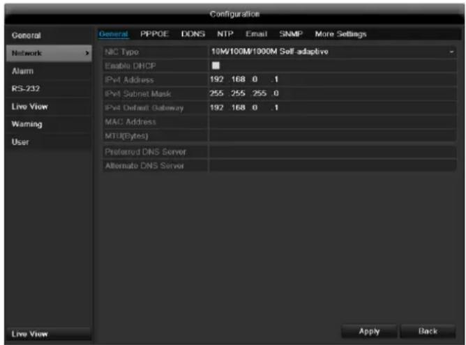
TAB General
| Parameter | Setting |
| NIC Typ | Set the transmission speed of the installed network card here. Tip: 10M/100/1000M self adaptive |
| Enable DHCP | Tick the box if the IP addresses are assigned dynamically via DHCP in the network. DHCP activated: Subsequent entry fields are inactive (parameters as-signed via DHCP). Note: If the IP addresses are assigned manually, ensure that DHCP is not active (box not ticked). |
| IPv4 Adress | Address of the network device in the network (manual assignment) |
| IPv4 Subnet Mask | Usually 255.255.255.0 |
| IPv4 Default Gateway | Address of the gateway for Internet access |
| IPv6 Adress 1 | Currently no functioning |
| IPv6 Adress 2 | Currently no functioning |
| IPv6 Standard Gateway | Currently no functioning |
| MAC Adress | Hardware address of the installed network card |
| MTU (Bytes) | Describes the max. size of the largest protocol data . |
| Preferred DNS Server | Address of the Domain Name Server (usually the IP address of the gateway) |
| Alternate DNS | IP address of the alternative DNS server |
| Report net-work interruption | Box ticked: Acoustic alarm in the event of a network interruption |

Note
In certain modes some of these settings cannot be selected.
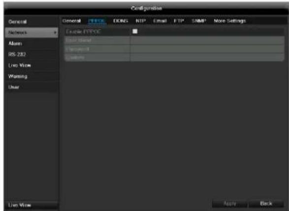
PPPOE
- Tick the PPPOE box, enter the user name (Internet access ID) and password, then confirm the password.
- Confirm the settings by pressing Apply.

Warning
Use PPPOE only if there is no router available.
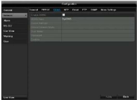
DDNS
- To use the ABUS DDNS function, you must first set up an account under www.abus-server.com. Please note the FAQs on the website when doing this.
- Tick the "Enable DDNS" box, enter 'ABUS DDNS' as the "DDNS Type", then enter www.abus-server.com or "62.153.88.107" under "Server Address".
- Confirm the settings by pressing Apply. The IP address of your Internet connection is now updated on the server every minute.
NTP
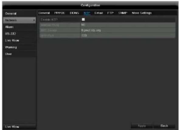

Note
The recorder can synchronise the time with an external server. Several server addresses are available on the Internet for this purpose.
- Tick the "Enable NTP" box and then enter the interval at which the synchronisation should be made again. Enter the IP address of the NTP server and the NTP port.
- Confirm the settings by pressing Apply.
In the event of an alarm, the device can send a message by e-mail. Enter the e-mail configuration here:
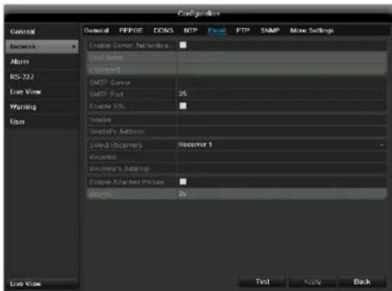
| Parameter | Setting |
| Enable Server Authentica... | Tick the box when authentication is made on the server of the Internet provider |
| User Name | E-mail account at the provider |
| Password | Password connected to the e-mail account |
| SMTP Server | SMTP server address of the provider |
| SMTP Port | Enter the SMTP port here (Default: 25) |
| Enable SSL | Tick the box to activate the e-mail encryption |
| Sender | Name of the sender |
| Sender's Adresse | Corresponding e-mail address for the e-mail account |
| Sender's Receiver | Select three possible recipients for the e-mail |
| Receiver | Enter the name of the recipient here |
| Receiver's Adressee | Enter the e-mail address of the recipient here |
| Enable Attached Picture | Tick the box when camera images should also be sent with the e-mail as photo files |
| Interval | Select the interval between the individual recordings (2 to 5 seconds) |
- Enter the parameters of the e-mail notification.
- Click on Test to send a test e-mail.
- Please clarify if your settings are correct and you have received a confirmation mail. Then click on Apply.

Note
The device sends an e-mail to the specified recipients.
If the e-mail is not received, check the settings and correct them.
If necessary, check the spam filter of your e-mail client.

Note
Because of the cause of compatibility please do only use E-Mail clients where a dial-up via SMTP is possible.
SNMP
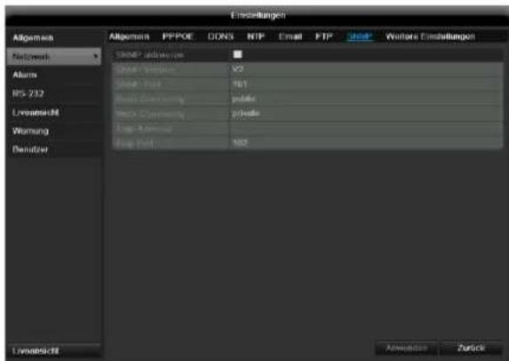
| Parameter | Setting |
| Activate SNMP | Activate the checkbox to create a connection to SNMP software |
| SNMP version | Version of the SNMP system |
| SNMP port | Enter the SNMP port (Default: 161) |
| Read community | Enter the “Key” according to the settings of your SNMP software. |
| Write community | Enter the “Key” according to the settings of your SNMP software. |
| Trap address | Enter the IP address of the SNMP manager |
| Trap port | Enter the trap port (Default: 162) |

Note
SNMP is used for monitoring the device status. For this you need SNMP software not available from ABUS.
Confirm the settings by clicking Apply and exit the menu with Back.
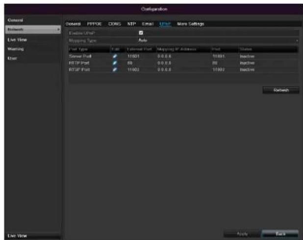
UPnP
| Parameter | Settings |
| Enable UPnP | Tick box to activate visibility in an IP network. |
| Mapping Type | Select here whether port mapping is to be conducted automatically or manually. |
Confirm the settings by clicking Apply and exit the menu with Back.
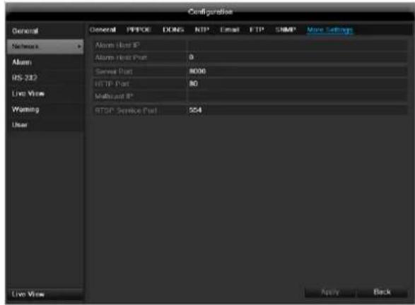
More settings
| Parameter | Setting |
| Alarm Host IP | Network address of the PC where the CMS is installed |
| Alarm Host Port | Port of your CMS Station |
| Server Port | Port for data communication (General: 8000) |
| HTTP Port | Port for web server (General: 80) |
| Multicast IP | In order to minimize traffic you can enter a Multicast IP. The IP address has to match the IP address of the PC running the CMS software. |
| RTSP Service Port | RTSP-port(Default: 554) |

Note
Server port 8000 and HTTP port 80 are the standard ports for remote clients and remote Internet browser access.

Note
With Alarm Host IP/Port you configure the address of your CMS software. The CMS software is notified when there is an alarm, and performs various reactions depending on the setting.
Warning
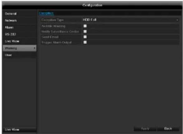
You can trigger a warning for the following error types:
HDD Full
HDD Error
Network Disconnected
IP Conflict
- Illegal Login
Video input/output signals not equal
- Exception Error
| Parameter | Notifications |
| Audible Warning | The device emits a repeating tone. |
| Notify CMS | Sends an alarm signal to a PC with ABUS CMS software. The software must be enabled and the recorder set to surveillance mode on the PC. |
| Send E-mail | An e-mail is sent to a specific e-mail address. |
| Trigger alarm output | See alarm settings. |
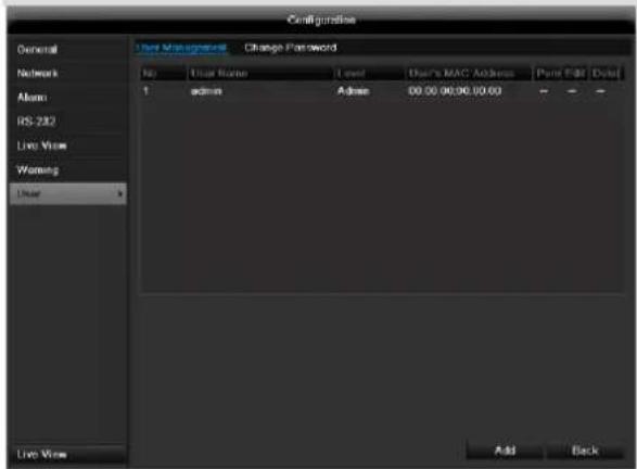
User

Warning
Note down the admin password.
The following password is preset
"12345"
You can add new users, delete existing users and change the settings in the "User Management" menu.
- To add a new user, select Add.
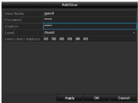
| Parameter | Setting |
| User Name | Unique identification |
| Password | Access code for the device (device management) Note: Change all passwords on a regu- lar basis, using a combination of letters and numbers. Note down all pass- words in a safe place. |
| Confirm | Enter the access code again here |
| Level | IMPORTANT: More access rights can be set on the Manager level than on the User level. |
| User's MAC Address | MAC address of the network adapter on the PC of the corresponding user Note: This limits access to the PC whose MAC address is entered here! |
- Enter the name and password and confirm the password in the field below.
- Select the level and enter the MAC address.
- Confirm the settings by clicking Apply.

Warning
Pay attention to the instructions below on assigning access rights.
Permission
Control the access rights of the user by clicking the "Permission" symbol. Only the access data of users added manually can be changed:
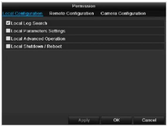

Note
The user can make the settings locally (i.e. on the device) or change the parameters.
The user can access the device via the network connection.
The "Camera Permission" tab is used to set access rights for individual cameras (network or local).
| Parameter | Setting |
| Local Configuration | Local Log Search Local Parameters Settings Local Advanced Operation Local Shutdown / Reboot |
| Remote Configuration | Remote Log Search Remote Parameters Settings Remote Serial Port Cntlro Remote Video Output Cntlro Two-way Audio Remote Alarm Control Remote Advanced Operation Remote Shutdown / Reboot |
| Camera Configuration | Camera Permission |

Warning
Change the general settings of the user (name, password, level, MAC address) by clicking the "Edit" symbol or in the TAB "Change password".
Camera
OSD
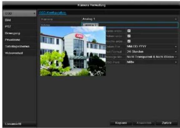
| Camera | Camera to be set |
| Camera Name | Allocation of camera name |
| Display Name | Activate / deactivate display of camera name in the live view |
| Display Date | Activate / deactivate display of date in the live view |
| Display Week | Activate / deactivate display of week in the live view |
| Date Format | Selection of date display type |
| Time Format | 12 hours / 24 hours |
| Display Mode | Settings relating to the presentation of camera name and date |
| OSD font | Changing the font size |
Image
Select the camera channel for processing under "Camera".
Use "Mode" to adapt the camera image to the light conditions with the help of preset settings or user-defined settings.
PTZ
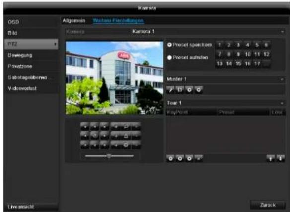
Saving and retrieving presets
- Use the arrow buttons to move the camera to the required image section and save the position, for example as Preset 1.
- Click on Call up to move to Preset 1.
Setting up and calling up patrols
- Create several presets to use for the patrol.
- Click on + to select a preset.
- Add more presets to set up the required patrol.
- Then click on the play symbol to start the patrol.
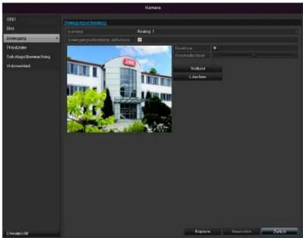
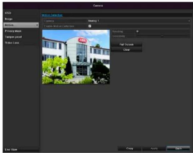
Motion
Select the camera channel under "Camera".
Select the checkbox for the motion detection.
Handling
Trigger Channel
When "Reaction" is clicked, the TAB Trigger channel appears (only with motion recognition):
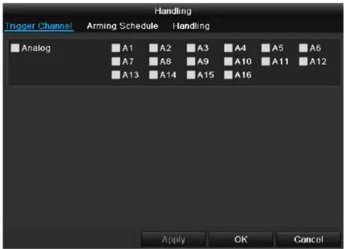
Select one or more camera channels that should carry out a reaction in the event of an alarm. Confirm the settings by clicking Apply and leave the menu with OK.
Armin Schedule
Select the TAB Arming Schedule. Here you set the times when the reactions in the TAB Reaction are triggered.
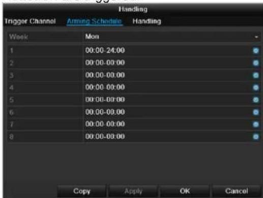
- Select the day and enter the schedule.

Note
In order to record using the motion recognition, you must set the time plan at recording (see p. 96).

Note
You can define up to 8 time periods (each from 00:00 to 00:00). The times in the individual periods must not overlap.
- Select whether the settings should be applied to all days of the week with using Copy.
- Confirm the settings by clicking Apply and leave the menu with OK.
Handling
Click on the TAB Handling.
Here you can configure the behavior of the recorder during a detected event (for example: motion got detected) by clicking the respective check box.
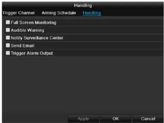
| Parameter | Notification |
| Full Screen Monitoring | The camera is displayed as a full-screen picture in live cast |
| Audible Warning | The device emits a repeating tone |
| Notify CMS | Sends an alarm signal to a PC with ABUS CMS software. The software must be enabled and the recorder set to surveillance mode on the PC. |
| Send E-Mail | An e-mail is sent to a specific e-mail address. |
| Trigger alarm output | See Settings for alarms |
- Confirm the settings by clicking Apply and leave the menu with OK
Private Zone
Select the camera channel under "Camera".
Select the checkbox for activating the private zone.
- Select up to four private zones with the mouse.
- Select Copy if the setting is to be applied for all cameras.
- Confirm the settings by clicking Apply and exit the menu with OK.
Tamper monitoring
Select the camera channel under "Camera". Select the checkbox for activating tamper monitoring.
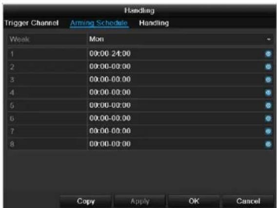
Armin Schedule
Select the TAB Arming Schedule. Here you set the times when the reactions in the TAB Reaction are triggered.

- Select the day and enter the schedule.

Note
You can define up to 8 time periods (each from 00:00 to 00:00). The times in the individual periods must not overlap.
- Select whether the settings should be applied to all days of the week with using Copy.
- Confirm the settings by clicking Apply and leave the menu with OK.
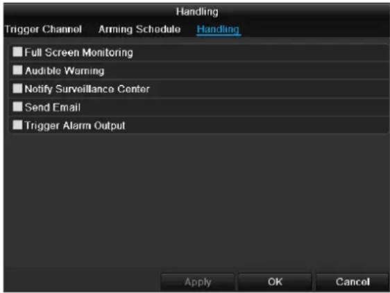
Handling
Click on the TAB Handling. Here you can configure the behavior of the recorder during a detected event (for example: motion got detected) by clicking the respective check box.

| Parameter | Notification |
| Full Screen Monitoring | The camera is displayed as a full-screen picture in live cast |
| Audible Warning | The device emits a repeating tone |
| Notify CMS | Sends an alarm signal to a PC with ABUS CMS software. The software must be enabled and the recorder set to surveillance mode on the PC. |
| Send E-Mail | An e-mail is sent to a specific e-mail address |
| Trigger alarm output | See Settings for alarms |
- Confirm the settings by clicking Apply and leave the menu with OK
Video signal loss
Select the camera channel under "Camera". Set the checkmark for the alarm in the event of a "Video Loss".
Armin Schedule
Select the TAB Arming Schedule. Here you set the times when the reactions in the TAB Reaction are triggered.
- Select the day and enter the schedule.

Note
You can define up to 8 time periods (each from 00:00 to 00:00). The times in the individual periods must not overlap.
- Select whether the settings should be applied to all days of the week with using Copy.
- Confirm the settings by clicking Apply and leave the menu with OK.
Handling
Click on the TAB Handling.
Here you can configure the behavior of the recorder during a detected event (for example: motion got detected) by clicking the respective check box.
| Parameter | Notification |
| Full Screen Monitoring | The camera is displayed as a full-screen picture in live cast |
| Audible Warning | The device emits a repeating tone |
| Notify CMS | Sends an alarm signal to a PC with ABUS CMS software. The software must be enabled and the recorder set to surveillance mode on the PC. |
| Send E-Mail | An e-mail is sent to a specific e-mail address |
| Trigger alarm output | See Settings for alarms |
- Confirm the settings by clicking Apply and leave the menu with OK
Record
Setting up
Open the main menu and click on record:
Schedule
The schedule is used to specify the recording times and triggers (recording type) for the cameras. Click on the "Schedule" tab:

Note
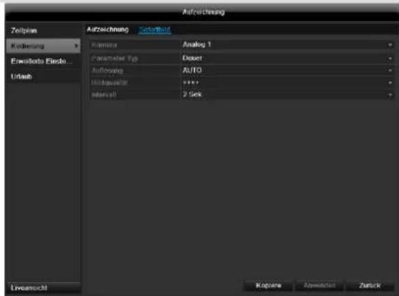
Because there is no difference between the settings for the TABs record and instant image, these are only listed once.
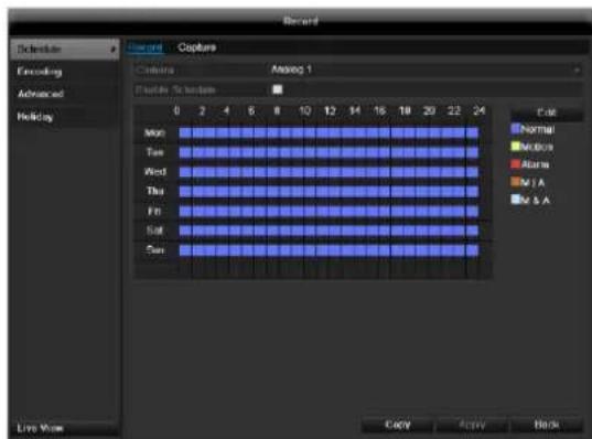
In the OSD, the hours of the respective days are listed from left to right (the days are listed from top to bottom). A colour key is shown underneath the days (i.e. the recording periods in the schedule are shown in colour according to the trigger (recording types)).
| Colour symbol | Key |
| Blue | Normal recording: Period in hours |
| Yellow | Motion detection |
| Light blue | Motion detection and alarm |
| Red | Alarm |
| Grey | No selection |
| Brown | Motion or alarm |
- Select the camera and click on the check box Enable Schedule.
- Click on Edit to specify the type and duration of the time plan
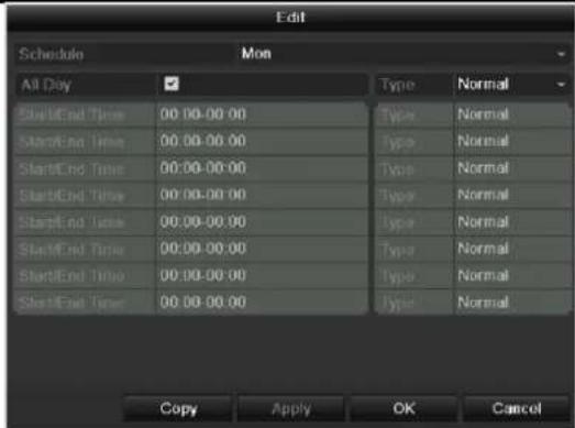
- Define the day to be set in the pull-down menu at 'Schedule'.
- Activate/deactivate 'All day'. If the full day is active, no definite times can be entered as the setting is now valid for the whole day.
- To make specific time settings, deactivate the "All Day" box.

Application example
Recording should run from 11:00 to 07:00. 2 time zones must be set up for this:
-
11:00 AM - 24:00PM
2.00:00AM-7:00AM -
Specify the recording type in the drop-down menu:
Time
Motion detection
- Alarm
Motion detection or alarm
Motion detection and alarm
- When making a specific time setting, you can define up to 8 time periods (each from 00:00 to 24:00). The times in the individual periods must not overlap.

Note
The "Time" recording type defines the time window where a recording is made.
The other events (e.g. motion detection and/or alarm) only trigger the recording after the specific event has occurred.
- At Copy you can take on this setting for other days or the whole week.
- Finalize your settings in the record screen with Apply and then OK.
Encoding
Record
The schedule is used to specify the recording times and triggers (recording type) for the cameras.
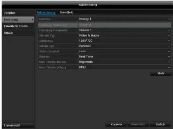
The following setting options are available in this submenu:
| Camera | Camera to be set |
| Encoding Para-meter | Stream to be set |
| Stream Type | Predefined video stream |
| Resolution | QCIF / CIF / 2CIF / 4CIF / WD1 |
| Bit rate | Select a variable or constant bit rate |
| Video Quality | There are various quality levels: +++: medium quality +++++: high quality |
| Frame rate | Setting for the stream frame rate |
| Max. bit rate mo-de | Select the mode for setting the bit rate User def. (512 – 3072) |
| Max. bit rate (kbps) | Setting for the maximum bit rate |
| Recommended max. bit rate | Recommended bit rate depending on the set resolution, frame rate, etc. |
| Lead time | Recording period before an alarm (in seconds) |
| Overrun time | Recording period after an alarm (in seconds) |
| Mark elapsed ti-me | Setting for the longest retention time for recorded files. |
| Record audio | Record audio |
| Activate 960 mode | Activated: Recording with WD1 resolution possible. |
Confirm the settings by clicking Apply and exit the menu with OK.
TAB Substream
The following parameters can be set:
| Camera | Camera to be set |
| Stream Type | Predefined video stream |
| Resolution | QCIF / CIF / 2CIF / 4CIF / WD1 |
| Bit Rate Type | Select a variable or constant bit rate |
| Video Quality | There are various quality levels: +++: medium quality +++++: high quality |
| Frame rate | Setting for the stream frame rate |
| Max. bit rate mode | General, user def. (512 - 3072) |
| Max. bit rate (kbps) | Display of the maximum bit rate |
| Recommended max. bit rate | 1344~2240 (kbps) |
Confirm the settings by clicking Apply and exit the menu with Back.

Advanced settings
Overwrite
You can specify whether older recordings are deleted when the HDD memory is full
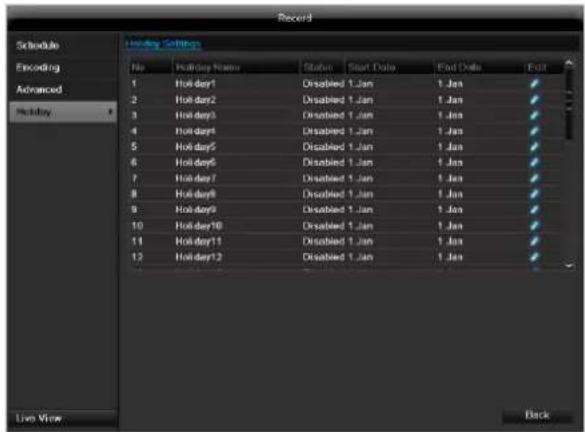
Holidays
In this sub-menu, 32 different recording settings for vacations or public holidays can be applied.
To apply these settings click on the "Edit" symbol:
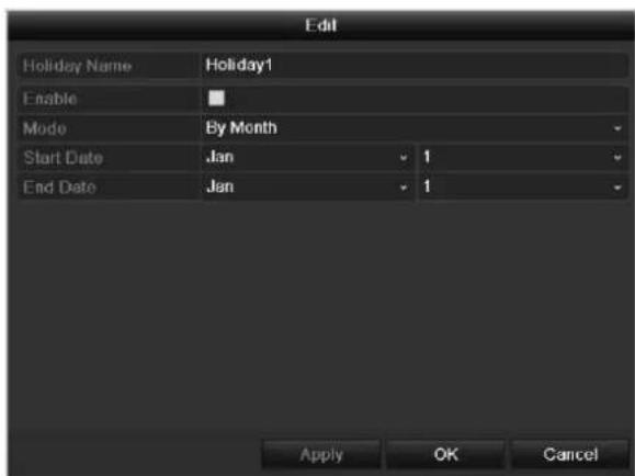
Holiday Name
Manual name entry of the vaca
| tion or holiday | |
| Enable | Activate or deactivate the set va-cation |
| Mode | According to date / week / month |
| Start Date | Selection of start date / start time |
| End Date | Selection of end date / end time |
Confirm your settings with Apply and OK.
HDD
HDDs

Note
The device can manage two 3.5" SATA hard disk drive.
Each of the installed HDDs must be initialised before the device can be used for recording. The device only detects the HDD and its assignment after initialisation has been made.

Warning
All data is deleted from the HDD during initialisation.
Ensure a data backup has been made in good time beforehand.
Installing the HDD
- Disconnect the device from the mains power and open the cover.
- Observe the applicable ESD guidelines when handling electronic devices and ensure they are earthed.
- Do not open the device in rooms with carpets or other surfaces that can become electro statically charged.
- Avoid bodily contact with all components on the PCB.

Warning
If you have questions regarding the information or cannot find the information you need, please contact your maintenance specialist.
- Install the HDD and then connect it.
- Reattach the cover and connect the device to the mains power supply.

Note
If the initialised HDD is not displayed, check the connections
Click on "HDD" in the menu to define settings relating to hard disc administration
HDD Management parameters
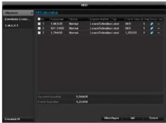
| HDD information | |
| No. | Shows the internal connection number |
| Capacity | HDD capacity (in GB) |
| Status | Shows the current status of the HDD: Not initialised Normal Error Standby |
| Features | ·Read-only: Read-only protection ·R/W: Read and write |
| Type | Local: Device HDD NFS: Network HDD If possible, avoid using NFS storage due to compatibility problems that may occur. |
| Free Space | Shows the approximate free memory for recordings |
| Delete | Remove the hard drive |
- Select the HDD by ticking the corresponding box.
- Start the process by clicking on Init.
- Confirm the prompt by pressing OK.
- The status bar shows the progress of the initialisation.
- Nach Beendigung des Vorgangs erscheint die Festplatte.
HDD settings of the cameras
Click on the "Advanced" submenu
Mode: Storage
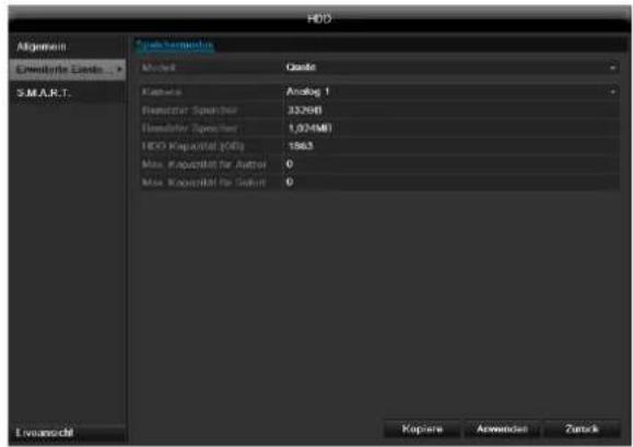
Camera
- Selection of the camera channel for processing.
Used Record Capacity
- File size of a recording file
HDD capacity (GB)
HDD capacity (in GB)
Max. capacity (GB) for recordings
- Specify the maximum recording size on the hard disk drive for each camera.
- Select Copy if the setting is to be applied for all cameras.
- Confirm the settings by clicking Apply and exit the menu with OK.
- Click Apply and confirm the restart in the next window with OK.
S.M.A.R.T.
S.M.A.R.T. means Self-Monitoring Analysis and Reporting Technology.
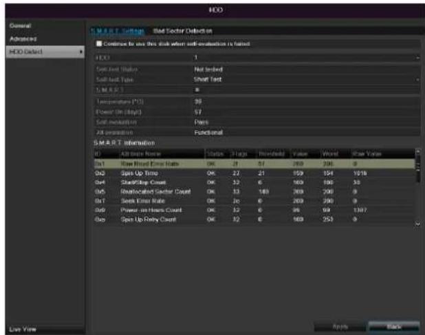
Click on the "S.M.A.R.T" submenu.
This information helps to recognise hard disc errors. For this reason, do not deactivate this feature if possible.

| HDD | Selection of the hard disk drive to be processed. |
| Self-test status | Shows the status of the current self-test |
| Self-test type | Select the type of the self-test. Short Test / Expanded Test / Transport Test |
| S.M.A.R.T | Click on the icon to start the self-test |
| Temperature (℃) | Display the HDD temperature |
| Switching on (Days) | Display the operating days of the hard disk drive |
| Self-evaluation | Status display of the self-evaluation |
| Complete evalua-tion | Status display of the evaluation |
Confirm the settings by clicking Apply and exit the menu with OK.

Important: If only one HDD is installed and this is set to "Read-only", then the device cannot make recordings.
Checking the HDD status
The status of each HDD can be checked in the "Maintenance" menu. S.M.A.R.T. information (Self-Monitoring, Analysis and Reporting Technology) is stored in the log data.
- Call up the log file and search according to the information/S.M.A.R.T. HDD.
- You can specify alarms to inform you of HDD errors.
- To do this, call "Warning" in the "Settings" menu.
Panic recording
Recording
Press the REC button or navigate to Panic Recording in the main menu to start manual picture/video recording.
Click on the "Recording" submenu.
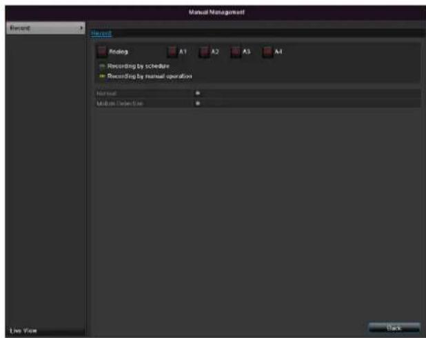
| Analog | Select the settings for all cam-eras Click “Off” or “On” to change the settings. On, green: Recording according to sched-ule, On, yellow: Recording with manual oper-ation Off, red: No recording. |
| Duration | Click on permanent recording to activate all channels for the whole day. Click “Yes” to confirm your se-lection. |
| Motion detection | Click the symbol to activate mo-tion detection for all channels for the whole day. Click “Yes” to confirm your se-lection. |
Playback
Press Configuration in the main menu and then Playback to search for video recordings after an event or a marking, or to view your saved images.
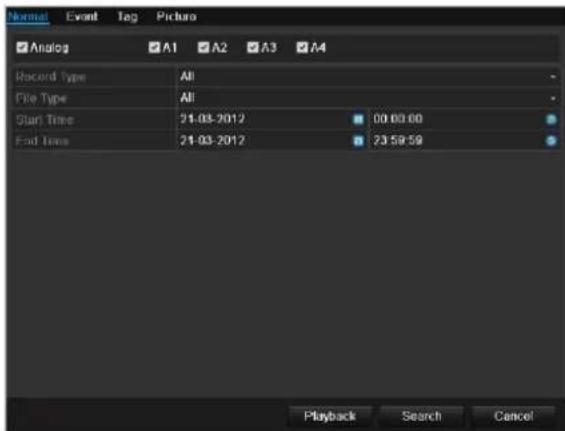
Continuous Recording
The following settings are available:
| A1 - A4 | Camera to be set |
| Record Type | Schedule, motion detection, alarm or motion detection and/or alarm, manual recording, all |
| File Type | Locked, unlocked, all |
| Start Time End Time | Enter the date and time |
- Click on Search to search for recordings with the corresponding settings. The results are then shown:
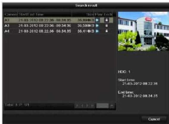
- Select the recording by clicking on the line and then on "Play"-symbol.

Note
You can return to events search at any time in the playback mode by performing a right click and selecting 'Video Search'.

Note
The sub-menus Tag' and Picture are almost identical with the menu described above and are therefore not listed separately. In the sub-menus Tag', searching does not take
place according to recording type, rather according to identification or a keyword of the markings' name
Event
Please klick on the TAB ,Event".
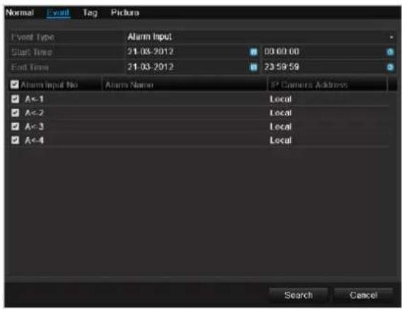
A list of all event types is displayed.
For "Event Type" select whether a search is to be made for recordings with motion (motion detection).
Select one or more cameras by activating the checkbox. Click on Search.
Select one or more event markings from the list which appears. Click on Details to obtain more information about the recordings.
Video Export
Duration
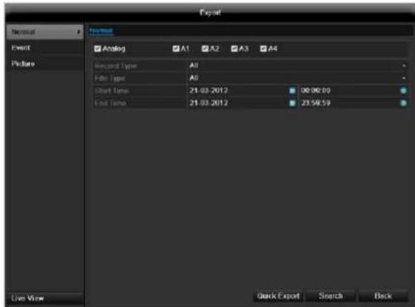
i Note
The export function is used to store important recordings on connected external media, such as:
USB media
USB HDD
DVD writer
-
When "Quick export" is selected, all recordings of the selected time span are exported. Please note that not more than 24 hours can be exported.
-
Enter the parameters.
- Click on "Details" to limit the search
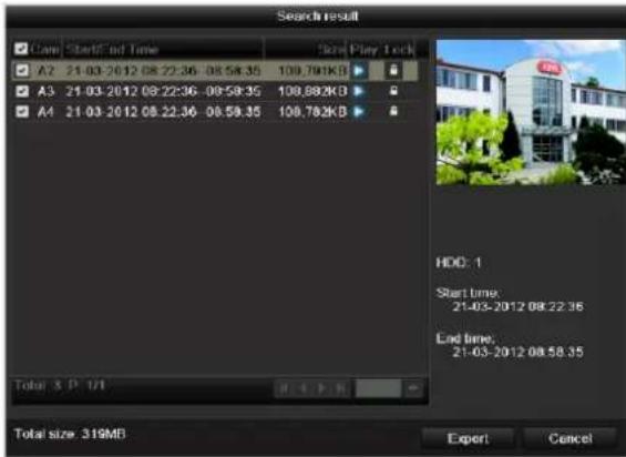
- The file size of the individual recording and the total size of all found recordings are displayed.
- By clicking the "Playback" symbol you can view the respective recording.
-
To block or unblock a file click on the "Lock" symbol.
-
Click on Export to access the export screen.
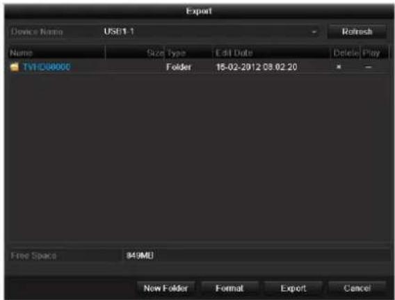
- Select the connected medium used for data storage from the drop-down menu.
-
If the medium is not displayed, click on Refresh.
-
If the medium is still not displayed, disconnect it from the device and reconnect the medium again. See also the manufacturer's specifications.
-
Click on Export to start the export process. The progress of the export process is then displayed.


Note
After the storage process is completed, the data on the medium can be selected and played on the player (which was also backed up). In this way, you can check whether the export has been made successfully.
Event (event type 'Motion')
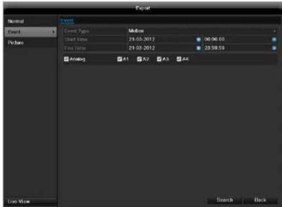
Define the time span of the recording being searched for by means of the selection fields at "Start time" and "End time". Select the camera by activating or deactivating the check box and click Search.
For both types of event, the following window appears after activating the Search button:
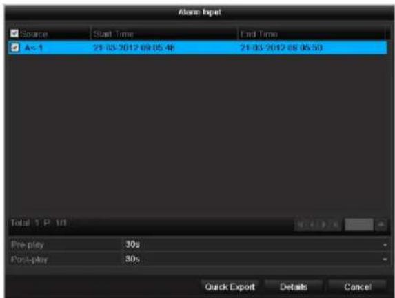
Select the files to be exported by activating or deactivating the check box. You can set the pre-alarm and post-alarm time at "Pre-play" or "Post-play". In this way you can define the length of your export video.
Click on Details to view the selected video. For more exact information on the Details window, see DURATION (p. Fehler! Textmarke nicht definiert.).
Note
The "Pre-play" recordings can only be viewed when recording has been carried out before the alarm.
Note
The sub-menus "Normal" and "Picture" are similar and are therefore not listed separately.
Maintenance

Note
This menu is used for device maintenance, and should only be operated by experienced users.

| Menu | Setting | P. |
| System Info | Device information (serial number, firmware status etc.) | 105 |
| Log Search | A search of recordings or information (S.M.A.R.T. HDD status) can be made in the log file according to certain criteria (alarms, exceptions, operation or information). | 105 |
| Import/Export | Used to export or import the settings | 106 |
| Upgrade | Carries out a firmware upgrade | 106 |
| Default | System reset | 107 |
| Network | Displays the transmission and reception rate of the recorder | 107 |
System Info
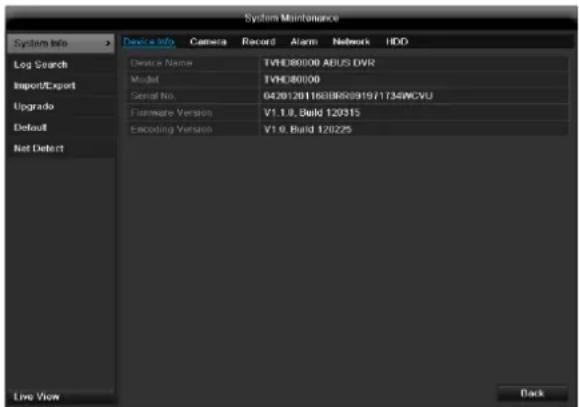

Note
The information menu shows the technical data for the device and information on the various settings of the cameras, recording etc.
This can be useful for support queries, for example.
Log Search
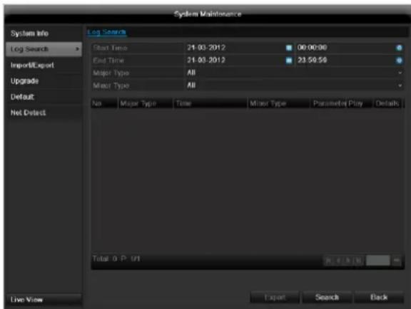

Note
An event search can be made according to the following main types, events and parameters:
All
Alarm
- Exception
Operation
Information
| Filter1 | Filter2 |
| All | - |
| Alarm | · All · Alarm Input/Output · Start/Stop Motion Detection · Start/Stop Tamper-proof |
| Exception | · All · Video Loss Signal · Video Signal Exception · Illegal Login · HDD Full · HDD Error · IP Conflicted · Network Disconnected · Exception recording · Video input/output signal not equal · Recorder buffer overflow |
| Operation | · All |
| • Power On • Abnormal Shutdown • Start/Stop Audio • Local Operation, e.g.: Shutdown/Reboot/Login/Logout/Configure Parameters/Upgrade/Start Recording • Remote Operation, e.g.: Export Record File/Alarm Arming/ ... | |
| Information | • All • Local HDD Information • HDD S.M.A.R.T. • Start/Stop Recording • Start/Stop Capture • Delete Expired Record • NetHDD Information |
- Select the event you wish to search for in the log, then select the sub-parameter.
- Enter the date and time under "Start Time" and "End Time", then click on Search.
3.The results are then displayed:
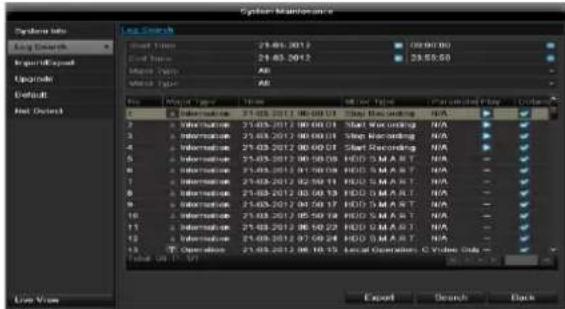
- The pages are changed using the navigation bar:

(1) (2)
(3) (4)
(5)
(6)
Note
To scroll forwards or backwards press (3) or (2).
To jump to the first or last page press (4) or (1).
To go to a specific page number enter it in (5) and confirm by clicking (6).
- Click on Details to see more detailed information.
- Click on Play to start the recording for the event, when necessary.
- Click on Export to back up the log file on a USB medium.
Import/Export
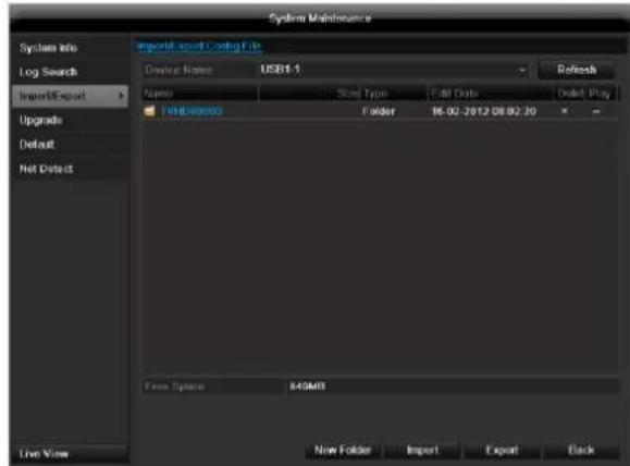
i
Note
The configuration data contains all settings made on the device since the start of operation. This data can be saved on a USB medium. You can then configure another device identically, for example.
Upgrade
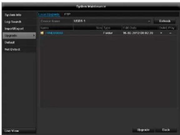
i
Note
A device upgrade can be made from a USB device or over the network.
- Copy the upgrade file to the main directory of a USB stick.
-
Connect the USB stick to a USB port on the device.
-
Select the USB port (click on Refresh, if necessary).
- Select the upgrade file and click on Upgrade.
- Wait until the device reboots.
- Check the firmware status in the "Maintenance" menu under "System Info".
i Note
Upgrades via FTP are made in the same way as detailed above. The PC must be in the same local network. Set up a PC as an FTP server. Enter the IP address of the FTP server.
Default
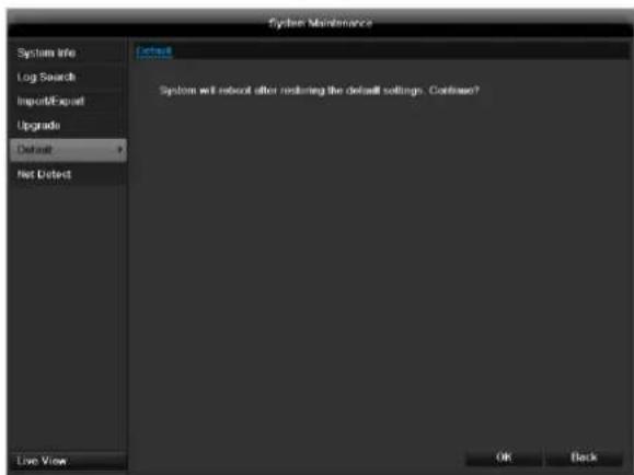
i Note
Note
In this process, the device is reset to the factory default settings.

Warning
All settings made since the start of operation are deleted (cameras, recording settings, alarms etc.)!
Avoid data loss by backing up the settings in advance. These can be imported again following the system reset.
Network
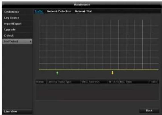

Note
Information regarding the network traffic and network interfaces are shown here.
TAB network load
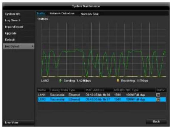
The amount of received and sent data is displayed graphically.
Depending on the network settings, the status and information for one or two network connections is shown in the field underneath the graph.
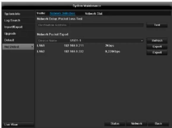
TAB Network Detection
In "Destination Address", you can check the connection to another device, such as a computer ('pinging'). Enter the network address of the device to be checked (e.g. 192.168.0.25) and press Test.

Information on two parameters appears:
| Parameter | Setting |
| Average delay | The time the pinged device needs to reply. |
| Packet loss Rate: | Displays the percentage of packets that were not transmitted |

Note
If the packet loss rate is high, we recommend that the "Network Test" is repeated.

Note
If the packet loss rate is still high, you should check that the cables are correct and not damaged.
The higher the packet loss rate, the poorer the connection between the pinged device and recorder.
For "Network Packet Export", you can export the settings of the individual connections or - depending on the setting - the connection.
-
For "Device Name", select a storage medium to save the settings to.
-
Click Export.

After the progress display finishes and initialization is successful, an information window appears. Close it with OK.
- Click Status to display the status of the LAN connections (connected/not connected).
- Click Network to change your network settings (see p. 85).
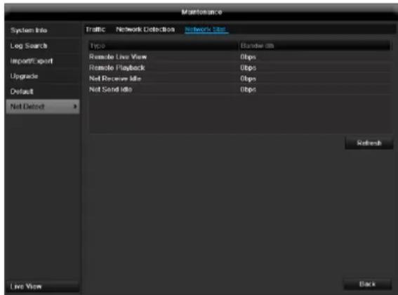
TAB Network Stat.
Displays all used in- and outcoming bandwidth.
You can refresh the data by clicking on Refresh.
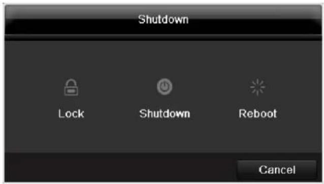
Shutdown

Note
- Select "Lock" to lock the operating menu.
- Select "Shutdown" to switch off the device.
- Select "Reboot" to reboot the system (switch off and back on).
Troubleshooting
Before calling the Service department, read the following information to determine the possible cause of a malfunction.
| Malfunction | Cause | Solution |
| No power | Mains cable not connected | Connect the mains cable securely to the socket |
| Power switch set to OFF | Turn the power switch to ON | |
| No current in the power socket | Use another device on the socket, where necessary | |
| No image | Screen not set for reception | Set the correct video input mode until an image from the recorder appears |
| Video cable not connected properly | Connect the video cable securely | |
| Connected modem is switched off | Switch on the monitor | |
| No sound | Audio cables not connected properly | Connect the audio cables securely |
| Devices connected over the audio cables are not switched on | Switch on the devices connected over the audio cables | |
| Audio connection cable is damaged | Replace the cable | |
| HDD is not working | Connection cables not connected properly | Connect the cables securely |
| HDD defective or not system-compatible | Replace with a recommended HDD | |
| USB port not working | Device not supported | Connect a compatible USB medium (USB 2.0) |
| USB hub is in use | Connect the USB medium directly | |
| Network access not possible | Network cable connections are loose | Connect the network cable |
| Network settings are incorrect (DHCP, IP address etc.) | Check the network configuration and correct it, ifnecessary (see page 85). | |
| Remote control is not working | Batteries inserted with the wrong polarity or are empty | Replace the batteries. To control the device with the remote control, point it at the remote control sensor on the device |
| Remote control too far away from the recorder | Use the remote controller within 7 metres from the device | |
| Signal blocked by obstruction between the remote control and recorder | Remove the obstruction | |
| Lighting too bright or fluorescent tubes in use? | Switch off strong fluorescent lighting in the immediate vicinity | |
| Recording not possible | No HDD or HDD is not initialised | Install and initialise the HDD |
| Sudden deactivation of the device | Temperature inside the device is too high | Clean the device and remove any obstructions from the ventilation area |
Device cleaning and care
Note
- Your device requires no maintenance.
- Protect the device from dust, dirt and moisture.
Technical data
Subject is to alterations and errors. The dimensions are approximate values.
| ABUS digital recorder | TVVR41200 | TVVR41210 | TVVR41220 | |
| Video compression | H.264 | |||
| Camera inputs | 4 | 8 | ||
| Camera outputs | Adapter cable for video outputs | |||
| Monitor outputs | Monitor: 1 x BNC (1.0 V p-p, 75 Ω), 1 x VGA, 1 x HDMI | |||
| Operating mode | Triplex | |||
| Resolution (live view) | BNC: PAL: 704 x 576, NTSC: 704 x 480 VGA: 1080P: 1920*1080/60Hz, 1280*1024/60Hz, 720P: 1280*720/60Hz, 1024*768/60Hz HDMI: 1080P: 1920*1080/60Hz, 1280*1024/60Hz, 720P: 1280*720/60Hz, 1024*768/60Hz | |||
| Resolution @ frame rate per camera (recording) | WD1, 4CIF, 2CIF, CIF, QCIF @ 25fps | |||
| Total frame rate | 100 fps | 200 fps | 400 fps | |
| Compression levels | 6 | |||
| Post-alarm memory | 0-30 sec. / 5-900 sec. | |||
| Storage medium | 1 x 3,5" SATA HDD | 2 x 3,5" SATA HDD | 1 x 3,5" SATA HDD | |
| Data backup | 2 x USB 2.0 | |||
| Views | 1 / 2 / 4 | 1 / 2 / 4 / 6 / 8 / 9 | 1 / 2 / 4 / 6 / 8 / 9 / 16 | |
| Recording modes | Manual, schedule, motion detection, alarm, motion detection and alarm, motion detection or alarm | |||
| Search modes | By event, date and time | |||
| Alarm input (NO/NC) | 4 | 8 | 16 | |
| Relay output | 1 (Max. load 12 VDC/1 A) | 4 (Max. load 12 VDC/1 A) | ||
| User levels | 2 (max. 31 users) | |||
| Network access | 1 x RJ45 10 / 100 Mbps | |||
| Parallel network access | 128 camera connections | |||
| Network functions | Live view, playback, data export | |||
| DDNS | ✓ | |||
| NTP | ✓ | |||
| Alarms | Acoustic warning, OSD signal, e-mail, CMS | |||
| Control | USB mouse | |||
| Audio | Audio In 1-4: RCA (2.0 V s-s, 1kΩ), Audio Out: 1 x RCA (2.0 V s-s, 1kΩ) | |||
| Software | ABUS CMS Software | |||
| OSD languages | German, English, French, Dutch, Danish, Swedish, Polish, Russian | |||
| Power supply | 12 VDC, 3,3 A, 50~60 Hz | 12 VDC, 5,0 A, 50~60 Hz | ||
| Power consumption | <10W (without HDD) | <15W (without HDD) | <20W (without HDD) | |
| Operating temperature | -10 °C ~ +55 °C | |||
| Dimensions (W x H x D) | 400 x 45 x 275 mm | |||
| Weight | ≤ 4.0 kg (without HDD) | |||
| Certifications | CE | |||
HDD storage capacity
In addition to the actual storage capacity of the installed HDD, the required storage space for recording and surveillance depends on the set resolution and frame rate of the recording.
On the included CD you can find a program in order to calculate the required amount of memory. In addition you find this software for download on our homepage together with the ABUS CMS software.
Overview monitor output combination
It is possible to connect a SPOT monitor. Use the table below to find out what combinations are possible. A tick indicates that the combination is possible, a cross shows that it is not.
| BNC + VGA | HDMI only | VGA only | BNC only | HDMI + VGA |
| ✓ | ✓ | ✓ | ✓ | ✓ |
Disposal
Information on the EU directive on waste electrical and electronic equipment
To protect the environment, do not dispose of the device with domestic waste at the end of its service life. It can be disposed of at one of the appropriate collection points in your country. Please obey your local regulations when disposing of material.

Dispose of the device in accordance with EU directive 2002/96/EC - WEEE (Waste Electrical and Electronic Equipment). If you have any questions, please contact the department of your local authority which is responsible for waste disposal. Used equipment can be disposed of, for example, by your local or municipal authority, the local waste disposal company or your dealer.
Information on handling batteries
- Always insert batteries with the correct polarity. Never attempt to recharge the batteries supplied and do not throw them into naked flames under any circumstances. Do not use different batteries at the same time (old and new, alkaline and zinc-carbon etc.). Remove the batteries if the device is not used for a long period of time. If used improperly, there is a risk of explosion and leaking batteries!
- Take environmental protection into account - used batteries should not be disposed of in domestic waste! They must be taken to a collection point for used batteries.
- Make sure that batteries are kept away from small children. Children may put batteries in their mouths and swallow them. This can cause serious harm to their health. If this happens, consult a doctor immediately.
-
Do not charge normal batteries, heat them up or throw them into naked flames (they may explode).
-
Change low batteries in good time.
- Always change all the batteries at the same time and use batteries of the same type.

Important
- Leaky or damaged batteries can cause chemical burns on contact with the skin.
In this case, wear protective gloves.
Clean the battery compartment with a dry cloth.
Important information on disposing of batteries
Your product uses batteries which are subject to the European directive 2006/66/EC and may not be disposed of with domestic waste.
Find out about the regulations for the separate collection of batteries which apply in your country.
Proper disposal of batteries helps prevent harm to health and the environment.
Batteries that contain harmful chemicals are labelled with these signs:
Pb = battery contains lead
Cd = battery contains cadmium
Hg = battery contains mercury
Information on the European RoHS directive
The device complies with the RoHS directive.
Compliance with the RoHS directive means that the product or component does not contain more than the following maximum concentrations of the following substances in homogeneous materials, unless the substance is part of an application that is excluded from the RoHS directive:
a) 0.1% lead (by weight)
b) Mercury
c)Hexavalent chromium
d)Polybrominated biphenyl (PBB) and polybrominated diphenyl ether
e) 0.01% cadmium (by weight)
Glossary
Overview of specialist terms
1080i
HDTV image signal with 1080 pixels and interlaced display.
16:9
Cinematographic aspect ratio on widscreen displays.
720p
HDTV image signal with 1280 × 720 pixels and progressive display.
CIF
Common Intermediate Format
Originally planned for converting PAL to the NTSC standard. CIF corresponds to a video resolution of 352 × 288 pixels (2CIF = 704 x 288 pixels; 4CIF = 704 x 576 pixels).
CINCH
Socket type used for analogue audio or CVBS video signals.
CVBS
Colour, Video, Blank and Sync - The simplest variation of video signals (also known as composite video). The image quality is comparatively low.
DDNS
Dynamic Domain Name System entry
Network service which provides and updates IP addresses of its clients in a database.
DHCP
Dynamic Host Configuration Protocol
Network protocol which allows the automatic connection of devices (clients) in existing networks. DHCP servers (e.g. Internet routers) automatically assign the IP address, network mask, gateway, DNS server and WINS server (when required). Only the automatic acquisition of IP addresses must be activated for the client in this case.
Domain
Name used for the identification of websites on the Internet (e.g. www.abus-sc.de).
Dual Stream
Dual stream is a video transmission method. A high-resolution recording and lower-resolution transmission are made over the network, for example. The main stream has a 4CIF resolution and the sub-stream has a CIF resolution.
DVR
Digital Video Recorder - A device used for recording different video and audio sources (analogue, digital). The data is compressed for recording and saved on hard disk drives (HDD).
H.264
(MPEG-4 AVC) - Standard method for the highly-efficient compression of video signals. Used on Blu-ray discs or video conference systems, for example.
HDD
Hard Disk Drive
Digital data storage on computers or DVRs.
GIGABYTE
Unit of capacity for storage media (HDD, USB, SD/MMC cards).
HDVR
Hybrid DVR - DVR used for recording analogue cameras and network cameras.
http
Hypertext Transfer Protocol
Method for transmitting data across networks. Primarily used for displaying websites in a browser.
INTERLACED
Method for improving the picture quality of a video signal without consuming extra bandwidth (scan pattern on every second line).
IP address
An address in the computer network based on the Internet protocol. Allows different devices to identify themselves in a network so that they are accessed specifically.
JPEG
Compression method for photo images with minimal loss. Most digital cameras save photos in JPEG format.
MPEG
Moving Picture Experts Group - International standard for the compression of moving images. On some DVDs, the digital audio signals are compressed and recorded in this format.
NTP
Network Time Protocol
Method for synchronising the time across networks.
SNTP (Simple Network Time Protocol) is also available, offering a simplified protocol.
NTSC
Standard television format in the USA. The method is different from the European PAL system in certain ways. A full-screen NTSC image is comprised of 480 visible lines and a total of 525 lines. 60 half-images are displayed per second. Compared to PAL, the system is more susceptible to colour errors.
PAL
Phase Alternating Line - European colour TV system. Uses 576 visible image lines. Together with the lines used for signal management, a full-screen image is comprised of 625 lines. 50 half-images are displayed per second. The phase position of the colour signal changes from line to line in the image.
PANEL
Interior of a flatscreen display (e.g. LCD or plasma panels).
PC
Personal Computer - Can be used as a remote site, either with the software supplied or over a browser.
Pixel
Short for "picture element", the smallest unit for digital image transmission or display.
PIP
Picture in Picture - Where two signal sources are shown on the screen at the same time. The second signal source is stored above the first.
PPPoE
PPP over Ethernet (point-to-point protocol)
Network transmission method used for establishing a connection over dial-up lines. Used in ADSL connections, for example).
PROGRESSIVE
Method for displaying, storing or transmitting moving images in which all the lines of each frame are drawn in sequence. This is in contrast to the interlacing used in traditional television systems.
PTZ
Pan-Tilt-Zoom
Pan, tilt and zoom function on motor-driven cameras.
RESOLUTION
Normal PAL television systems show images in 576 lines, normally with 768 pixels. HDTV works with at least 1280 × 720 pixels.
SCREEN SIZE
Size of the display from the bottom-left corner to the top-right corner in inches or centimetres.
Browser
Program for viewing websites on the Internet.
USB
Universal Serial Bus
Serial bus connection, used for connecting media whilst in operation. Maximum data rate for USB 2.0: ca. 320 Mbit/s (ca. 40 MB/s).
VGA
Video Graphics Array - Standard interface for analogue video signals in PCs (primarily deals with RGB signals).
ZOLL (inches)
Typical unit of screen size. One inch is equivalent to 2.54 centimetres. The most common sizes of 16:9 displays are 26 inch (66 cm), 32 inch (81 cm), 37 inch (94 cm), 42 inch (106 cm), 50 inch (127 cm) and 65 inch (165 cm).
Internal HDD
The internal hard disk drive (HDD) is very sensitive. Operate the device according to the following instructions in order to avoid drive errors. Important recordings should be backed up on external media to avoid unexpected data loss.

Note
- Do not move the device during operation.
- Moisture inside the device can condense and lead to HDD malfunctions.
- When the device is turned on, never remove the mains plug from the socket or interrupt the power supply using the safety switch.
-
Do not move the device immediately after switching it off. To move the device, carry out the following steps:
-
Wait until OFF has been shown on the display for at least two minutes.
- Remove the mains plug from the socket.
-
Move the device.
-
Data on the HDD can be lost in the event of a power failure during operation. Use an uninterruptible power supply (UPS)!
- The HDD is very sensitive. Improper use or unsuitable surroundings can damage the HDD after some years of use. This may be indicated by the playback stopping unexpectedly or visible "mosaic" effects in the image. In some circumstances, there are no prior signs of a HDD malfunction.
- In the event of a malfunction, no recordings can be played. The HDD must be replaced in this case.
ABUS 4/8/16-channel analog digital recorder
TVVR41200 / TVVR41210 / TVVR41220
Manufacturer:
86444 Affing (Germany)
ABUS 4/8/16-kanaals 650 TVL realtime digitale recorder TVVR41200 / TVVR41210 / TVVR41220

Firmware Upgrade 165
Standaard 166
Netzwerk 166
Uitschakelen 168
Display 168
Installingen: Opname 168
S.M.A.R.T. betekent Self-Monitoring Analysis and Reporting Technology.
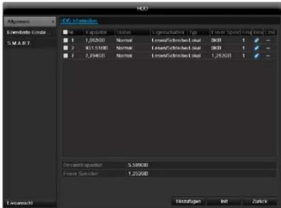
| BNC + VGA | HDMI only | VGA only | BNC only | HDMI + VGA |
| ✓ | ✓ | ✓ | ✓ | ✓ |
Afvoeren
Surcharge/surtension 187
Cables 187
Spcifications techniques 228
Surcharge/surtension
Chere cliente, cher client,
S.M.A.R.T. signifie Self-Monitoring Analysis and Reporting Technology.
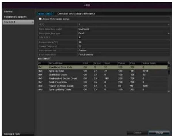
| BNC + VGA | HDMI only | VGA only | BNC only | HDMI + VGA |
| ✓ | ✓ | ✓ | ✓ | ✓ |
c)chrome hexavalent,
d)biphenyl polybromé (PBB) et polybromodiphénylether
Common Intermediate Format
'PPP over Ethernet' (protocole Point-to-Point)
'Universal Serial Bus'
Udforelse at Standard 282
Indhold
Netværk. 282
Nedlukning 284
Display 285
Indstlinger: Optagelse 285
Indstlinger:Netvark. 285
Installation at hardisken

Advarsel
IPv4 Address: 192.168.0.50
IPv4 Subnet Mask: 255.255.255.0
IPv4 Default Gateway: 192.168.0.1
Preferred DNS Server: 192.168.0.1

Henvisning
| BNC + VGA | HDMI only | VGA only | BNC only | HDMI + VGA |
| ✓ | ✓ | ✓ | ✓ | ✓ |
Bortskaffelse
"Dynamic Host Configuration Protocol"
"Universal Serial Bus"
Seriel busforbindelse til tilslutning af f.eks. lagermedier i Iobende drift. Maks. anvendelig datarate ved USB 2.0: ca. 320 Mbit/s (ca. 40 MB/s).
HDMI/VGA
86444 Affing (Germany)
S.M.A.R.T. to skrot z ang. od Self-Monitoring Analysis and Reporting Technology.
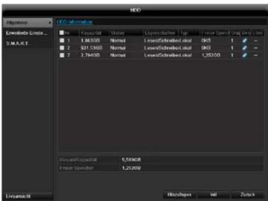
| BNC + VGA | HDMI only | VGA only | BNC only | HDMI + VGA |
| ✓ | ✓ | ✓ | ✓ | ✓ |
Utylizacja
,Universal Serial Bus'
YcTaHObKa JecTkoTo DnCKa 359
PoiokJIIOUeHne 359
KoHfUpyaun npnbopa 359
Baxhble yka3aHnno TeXnke 6e3onacHocTn 360
IcnoJb3yIte NCKJIOUHTeJIbHO JXecTKne DNCKN, pa3peHHeBle DnB BnDEo3aNNCn I pa60TbIB KpyrIocyToCHom peKmE 7DHeB HeDeHIO.
Iopknoyehne

Yka3aHne
YuTHe MNHMaJIbHbI paJNyC npn npokJaKe Ka6eJIa! Ka6eJIb He crI6aTb!
- CoeHHnTe BCE daTUnKc TpeBOXhbIMn BXOdaMn.
2.ПодклочиMe MOHITOP K pa3bemy VGA, BNC nHnHDMI. - NpoknIOUHTeMbIbK pa3bemy USB
- Co3daIte ceTeBOe NOdkJIIOUHeHne, NocNe 3TOrO yCTpoIcTBo 3aNyCTNTcA BtOMaTNUeCKn.
KoHcHpyaun npn6opa
yka3aHne
CneyuTe yka3aHnM B OTdeIbHoN KpaTko INcTpkyLnn.
BbInonHnTe OTdIeIbHbIe IaRn «POMOuHnKa HAcTpoEK》,cM. cTp.16
BbINOHNHTe KOHfumpyaunO cneDyUoux HacTpoek B daHHoN NocJeDoBaTeNbHOCTn:
Bb6op 3bka noIb3OBAteJIbCKOro nHTepceIca
- HactpoynAdmnHnctpaTopa
- HacpoKa BpeMeHn (daTa, BpeMa...
- HactpoiKcetn
- YnpabJIeHne XeCTKIM DnCKOM (yCTaHOBKn I T.D.)
- Hactpoyn 3aanns
yKa3aHne
O3HaKOMbTeCb c INHΦOpMaζneH ha caIte ABUS (www.abus.com) o Hαπηνι nocJIeHNxO6HOBJIeHn BCTpoEHHORo nporpaMMHOrO oBeCneUeHnДЯ daHHORO npiδopa n yctaHOBNTe nx.
i yKa3aHne
IocneJeUouee N3MeHeHne DaTbI nnBpeMeHN MOKET npNBecTe K noTepe daHHbIX!
Baxhblc yka3aHnno TeXnke 6e3OnaCHOCTN
Onncahne cIMBOJIOB
B INHCTpykunn Ha npnbope nCnoNb3yIOTc CneDyUOuNE CIMBOJbl:
| СИМВОЛ | Сигнавльhoe СLOBO | Зачения |
| ! | Прedeуpreneж- дени | Прedeуpreneителовий 3нak onaCHOCTN ТравмирOBаня илпonaCHOCTN Дли 3дорOBь. |
| Прedeуpreneж- дени | ПрedeуpreneITelовий 3нak onaCHOCTN ТравмирOBаня эл ekтуческIM наразоженем илпonaCHOCTN Дли 3дорOBь. | |
| Вaxная инфор- maця! | Уka3анue по 6e3ОасноCTN в СВЯЗС CBОЗMOЖБIM nobржденим пriбoga/ КOMПLEKТУЮших. | |
| i | Уka3анue | Вaxная Информаця |
B TeKCTe nCNoJIb3yIOTc CneDyUOuNe cHOCKn:
DanHbI np6op 6bln n3roTOBJeH npn co6JIOeHN MekHyapOHBix CTaHdApTOB 6e3OnacHOCTN.
3JIeKTpOnuTaHne
-
IcnoIb3yIte dIaHaHHoro npH6opa ncknOHTeIbHo nCToUHk 3NeKTPoNTaHn, HAnpJxKeHne KOTopOro COOTBETCTByeT yKa3aHnM Ha 3aBOdCKoT Ta6nUke.
-
EcIn BbI ToHr He 3HaTe XapaKTepnCTNk Cetn 3JIeKTPoPiTuHn, O6paTntEcB BaUy 3HepreTnueckyU KOMNaHnU.

PpeynpeKdeneHc
Ppeynpeinte yteky nHΦopMaunn.
PpmeHnTe np6Op noKIOuNb erO K
BeCnpepbIBHomy nCTouHNY nHTaHNA USV c
3JIeKTPnueckm PpeoxpaHNTeJEM.
- Ppeep npoBeeHnem pa60 nO texo6cnykBaHNO u yctaHOBKe OTKInouHTe np6Op oT 3JeKTPocetN.
BkIIOUeHne n BbIKIOUeHne daHHoro npnbopa n3OJIpyeT erO ot ceTu 3NeKTpOnnTaHn He NOJHOCTbIO.
-Дяп полнои n3оляци npибopa ot элькторун Heo6xOdmo BbIHyTb WTeKepe n3 WTeKepeHoi po3eTKn.
TOMy np6op DoJxHc6bITb yCTaHOBJeH TaK, T06bl 6bl Obecneuen pRMOu
6ecPpeTCTBeHHbI DOctyn K WTeKePHo PO3eTK
Dnra TORO, IN B Cnyae Upe3BbUaHoi CNTuaUN
MOxHO 6bl NO HeMeDJIeHHo BblHyTb WTeKep N3 PO3eTKn.
-Bo n36eKaHHe onaCHOCTn BO3HKnHOBeHnI NOxapa npn DOJROM HeNCNoB3OBAHH npu6opa, Heo6XoIMMo BbHyTb 1TeKepe n3 po3eTKn. Pnp yrpo3e nonadaHnMOnHH,do npu6NHexHn rpo3bl nn 6ypn, o6ecToyTe npu6Op nnn noDKlIOHTe erO K IVbI.

PpeynpeKdHne
OTkpbIBaTb npnbop camocToIeIbHo 3anpeueHc! Bo3MOxHa onaChOCTb nopaxeHn eJIeKTPuYeCKM TOkOM! Pn Heo6xOdmoCTn OTkpBITna npnbopa o6paTInTeCb K obyuEHOMy npoPeccNoHaIbHOMy nepcoHaJy IIN CneuaNtCTy no yctahOBKe mOHtAgy.
- YctaHObKa I nepeyCTaHOBka JxecTKoro DnCKa DOJXHa Ipn3BOIDtbcra O6yuHbIM NepcoHaIOM IIN BaUMC nEuaNCTOM NO MOHTaxy I yCTaHOBke.

PpeynpeKdHne
Pa60tbl no c6opke n MoDnΦkaCn np6opa, eCN TAKOBbIe BbINOJIHrOITc
HeKBaIIuΦNcIPoBaHHbIM NepCOHaNOM, BeyT K
NOTepe rapaHTnHbIX o6ra3aTeJIbCTB.
Mb coBETye O6paTbCk CneUaNCTy dny
yCTaHOBKn JecTKOrO DnCKa.
Ppi HeHaJNeJaSei yCTaHOBKe JecTKOrO DnCKa
rapaHTnTepReT CBOO CnNy!
Peperpy3ka/PepeHanpJxKeHne
CTapaIteCb He IOnyckaTb Npeperpy3Kn UTeNceJIbHbIX pO3eTOK, yDInHnTeJIbHbIX Ka6eNei aAdanTePOB, TAK KaK 3TO MOKeT npUBeCTN K BO3HNKHOBeHIO NOxapa nn Yuapy TOkOM.
-Bo n36exhaHne BO3HNKHOBeHnRA NOBpeXdEHn BcIeDCTBVe NpeHApJxKeHnRA (HapPIMep, PpN rpo3e), nCNoB3yIte 3JIeKTPnueckn npedoxpaHnteIb.
Ka6eJb
- He BbITACKnBaIte Ka6eIb n3 po3eTKn 3a npoBOd, BO3bMNTecb 3a uTEKeP.
3anpeueho 6paTbCMAKpbIMn pykamn 3a KaBeJb, TaK KaK 3TO MOKeT Bbl3BaTb KOpOTKoe 3aMbKaHne IN npBecTN K nopaxHeHIO 3JeKTpUeCKM TOKOM.
He cTaBbTe np6op, Me6eIb nIIN dpyIe TjKeJIbIe npEIMetbI Ha Ka6eIIN CJIeIITe 3a OTCytCTBnEM nepeRIOB,OC6eHNO B MecTx y IWekepa IrHe3dax NOdkNIOUeHnKa6eI.
3anpeueHcBopauBaTbKa6eBBy3eIN COeHNrTaC npuMn Ka6eJAMN.
- Bce Ka6eHn DoJXHbI 6bITb npOJKeHbI TaK, YTO6bl Ha HnX He NaTyn N 6blNo oBeCneHo 6ecnPenrTCTBENHO nepemeueHne.
- Поврждень сею кабел может CTаТь
пунно похара пл поразенья злестуческIM
ТOKOM. Перюдочи поювodи чу
Кабел.
- He n3MeHnTe n He npOn3BODnTe MaHnPyIaCn Ha cTeBOM Ka6eJe n WTeKepe.
He nCnoJIb3yIte aadantepHbIe wTekepbI nn ydINHInTeJbHbIe Ka6eJI, KOTOpbIe He COOTBeTCTBYIO T DeNCTByIOUIM HopMaM 6e3ONaChOCTu, N He n3MeHnIte Ka6eJI 3NeKTPoPNTaHnI n CeTu!
MecTo yCTaHOBKn/YcNoBn3KcnIpyTaun
- YctaHOBHTe np6Op Ha TBepDoH,poBHOn IOBepxHocTn. He cTaBbTe Ha np6Op TJaKeJIbIe IpeDMeTbl.
- Pnp6op He npedHa3NaueH dIg 3KcnnyatauIN B NOMEeHNx C BbICOKO TempeatypoN IN BnaXHOCTbIO BO3dyxa (HaNPmep, B BaHHoKOMHaTe) INC 60JIbWHM CKONNeHEm Iblnn.
- Temnepa type 3KcnjyaatauH IN BnaJXHOCTb BO3dyxa: -10°C Do 55°C, MACK. 85% OTHOCHTeHOB IN BnaJXHOCTN. 3Kcnjyaataua np6opa DOJXHa INPOIN3BOIDNTBCA TOJbKO BYMEpeHHOM KJIMMaTe.
CneJeTe 3a TEM, yTo6bI:
- Bcerda 6bIa oBecneueHa DocTaOuHnBa BeHTnlaCnna (He cTabTe np6Op Ha noIkn, TOnCTbI KOBep, Ha KPOBaTb NII B MeCTa, rDe BeHTnlaCUNHOHbIE OTBepCTna 6ydyT npIKpbITbI, OCTabTe C KaXdoN CTOPHbI paCCToHnE MNHMym 10 cm;
B6Iin3n npnbopa He HaxoDInIOcb Bo3deJeCTbYIOxHnHa Hero npraMbx NcTOHnKOB TeNla (HaNPmep, CnCTem OToPJIeHn);
Ha np6op He naaI npraMoCOnHeHbI CBETnnn CInbHOE NCKycCTBeHHoe OCBeUeHne; - npu6op He haoDnncB H enocpeicTBeHHoN 6n3nOT MarHnTHbIX noJe (HaNPmep, rpoMkoROBOpntenei);
- ICTOUYHNIOTKpbITOrOOrHn(HaNPIMep,rOpAUNe CBeu)He HaxoJINcB B6IIm3n Pnp6opa JIn6o 6blnn paCNOJIOXeHbI HaD Hm;
- He donyckaIcKoHTaKT C 6pb3ramN I KaJIaMn BObl, a TAKKe arpeccBHBbIM NIKKOCTaMn;
B6JIN3N 3KcNpyaTnpyEmo np6opa He HaxOJIInCb KnIKoCTN.3anpeucaTe norgykaTb np6Op B
KINKOCb (He CTaBbTe HAnOJIHHeHHbIe KINKOCrAMn IpeDMeTbI PRAOM C pN6Opom NnHa Hero: HanpImep, Ba3bl Nn);
BHTpb He nonaapan HnOpDhble npedMeTbI;
-Прибор He поьергалс сильним перетадam Temператyp, Иначе BO3MOЖно ообразовине KOндehcaТа ИЗ ВлжHOCTN BO3dUxha, YTO MOЖET npINBECTN KOPOTKOMY 3JIeKTPNueCKOMY 3aMbIkaHIO;
- np6op He noBepraC8 3HaunTeNbHbIM COtpceHnM nB6paunm.
TexHnueckoe o6cnykBaHne n yXoD
Pa60TbI NO Texo6cnyxuBaHInIO Heo6xoDnMbI B Cnyuae, ecn np6op nobpekden. HanpImep, ecn noBpeKdeHbI wTekep, Ka6eIb nn KOpNyc, Bo BHytpb np6opa nonaJiaXdkocTBnn npeDMtebl, np6op noDBeprcrBo3dEiCTBnIO Doxxy nn BlarN, ecn pa6ota np6opaOcyueCTBnAreTcC nepe6oamn nn np6op noDBeprcnaJeHHIO.
- 06ecToBTe np6Op dIЯ npOBeeHnpa6oT no Texo6cnyKuBaHHIO (HaNPmEp, OOnCTke)!
- Пи установлени дыIMO6pa3OBaHnna, NOBHeHnne06bIHybIX 3ByKOB nnn 3anaxa He3aMeIITeIbHO BbIKIOUHTe np6op n BbIHbTe wTeKepe n3 po3eTkn. B daHHbIX cnyaX danbHeNsa 3KcPnyataunnp6opa do npoBeDeHnna npOBepKn cneuaJIncToM 3anpeueHa.
-Дпяnpоведеня BCex pa60T no Texo6cnykBaHnIO o6paTNTecb K KBaJIINФИцpoBAHHOM cyeuaJIInCTy.
3anpeaaetc0KpbBaTb Kopnyc npnbopa n KOMnIeKTyUoHx. PnOtKpbTOM Kopnyce cyuectByet ONaCHOCTb nopaxKeHn8 3JIeKtpnueckm TOKOM!
OuNTKy npn6opa nnybTa ynpaBneHn npOn3BOUntb BnaXhbIM MaTePnAnOM (caNcETko).
He nCnoIb3yIte paCTBOpnteJIu, cInpT, pa36abJHOUcne cpeIcTBa n.T.D. OHmMOrYT nobpeIITb NOBepxHOCt b np6opa. - 3anpeueHNO npMHeHne CNeDyUOxN BeUeCTB:
COJIeHa BOda, CpeIcTBA OTHaceKOMbIX, XOpcoIepKaUaIne N KICIoTHbIe pAcTBOpHTeIN (HaTaBip), YnCTaUe NopoWKn. - AkkypaTHo npotepeTb NOBepxHocTb XNONHaTo6yMaXHo nCanPeTKoN Do NOnHoro BblcIxAHn.

PpeynpeKdHne
Pnp60ppa6oTaETnOanChbIMHa npjxHem.
Ito npuHne np60p pa3pewaeTcra
OTkpBaTb TOJbKO yONHOMOeHHOMy
nepcoHaNy,meHOeMy CneuaJIbHOe
pa3peSeHHe.Bce pa60TbIO Texo6CnyKBAHIO
n cepBnCy DOJIXHbI pOn3BOaNTbcΦnPmAMn,
HMeIOUIMN Ha 3To pa3peSeHne. HeHaIeXaIeI peMOHT MOxET CO3DaTb CnTyauIu yIrpO3bl Xn3Hn dIg POnb3ObaTeJI np6opa.
BbOdB3Kcnnyatauio
-Перед ВВОДМВЗКСПУATAUHNO Heo6xOДМо co6н�дь Се уka3aHnno NO texHnke 6e3OnaCHOCTи nЗКСПУATAUIN!
- OTKpbBaTb KOpnyc ToJIbKO dIy yCTaHOBKn JecTkoro dNcKa.

PpeynpeKdeneH
Y6eIITecb npu yCTaHOBKe B IMeIoUeIcyaTahOBKe BVdeOHa6JIoDeHn, YTO BCE pnpboiOTKIOUeHbI OT CETN BbICOKOr HAnpJxKeHn I ceni Hn3KOrO HAnpJxKeHn!

PpeynpeKdneHc
B cnyuae comHeHn He npOn3BoDnTe MOHTaKa, ycTaHObKn nPpOKnaKn Ka6eIra camocToTebHo, a npedocTaBbTe 3TO kCneptam.
HeHaJIeKaIeE u HeKBaJIuHcIuNpObaHHOe BbIOnHHeHne 3NeKTpUcEcknX pa6oT u pa6oT no yCTaHOBKe np6OpOB B DomauHnx ycNoBnx npEdctabJraet OanachocTb He TOnbKO dJa Bac, Ho I dJa DpyInx JnC.
CoéHnHTe Ka6eJem yctaHOBneHHbIe np6opbl, TaK YTO6bl CeT BbICOKOHa nApjXeHn I cenb Hn3KOHO nApjXeHn 6bln IpOJIOXeHb O TdEJIbHO dpYr OT dpyra, He nepeceKaINc bIu NHe MOrnn nepeceYbcA B CJIeDCTBne DeΦekTA.
Дети
3JNEKTPnueckne np6opbl He npedHa3NaHeHbI dIa detei! He octabnayte Detey noIb30BaTbcr 3JNEKTPnueckmnp6opam6e3 npncMoTpa.Detu MOyT He OCO3HaTB Bo3MOxHOn onaChocTu.Mekne DeTaIIpnporJIaTbIBAHm MOyT 6bITb KIN3HeonacHbl.
XpaHnTe 6aTapeu n aKKymyIaTopb I HneOcTyIhOM dIa MaIeHbKnx DeTei MeCTe. Pn npOrIaTbIbAHn 6aTapeu nn aKKymyIaTopa Heo6xOdImo HeMeIeHHO o6paTntbCra 3a MeDInuHCKoI NOMouIbIO.
XpaHnTe ynaKOBouHyIO nIeHky TaK JKe B HeIOCTyINHom IJra DeTe N MeCte. Bo3MOxHO ydyuWeHne!
-Данн布局прбор He npedha3haeHдя DeTei. Пужинсты DeTani ри HeHaJnEkaUeM npIMHeHm MOrY BbICKaKNBaTиnpuHHTb DeTAM noBpeXdEHn(HanpIMep,dЯ rna3).
BVeJeHne
Ybaxaemblknehtbl!
Mby 6naorapnBac 3a npno6peHne daHHoro npoayka.
DaHbI np6op COOTBeTCTByet Tpe6oBaHnM DeiCTByuOxN X DnpeKtNB EC. Deknapaun o COOTBeTCTBnIOCTynHa no aDpecy:
KoMaHaNABUSecurity-CenterGmbH&Co.KG
Linker Kreuthweg 5
86444 Affing
GERMANY
Дя coхpaheHЯ DAHHORO o6ctoTeNbCTBa n o6ecneHЯ 6e3oNaChOH 3KcNpyatauN Bb Ka K POnb3OBaTeHb O6raHb Co6IIOdaTb DaHHyU INHCTpyKuH!
Ipeed npimHeHnem npOyKta O3HaKOMbTeCb C NOHOn HNCTpykUe, 6paTne BHMaHne Ha yKa3aHnno 3KcPnyatau n I texHnke 6e3oNaChocTn!
Bce Ha3BaHnIaΦnM n IpoDyKTOB YBnIOTc TOpROBbIMn MapkAmn COOTBeTCTByIOSe O BnaIeJIbua. Bce npaba 3aunIeHbl.
Ecn y Bac Bo3HKnBOpocbl, o6patntecb K BaWemy cneuaNCTy no MOHTaxy nn dInepy no cneuaN3npoBaHHbIM npodaxam.

NCKIIOUeHne OTBeTCTBeHHOCTn
DaHnHa HnCTpyKu nno 3Knnyatau nn 6blna coCTabHeHa cambim TuaTeNbHbIM o6pa3om. B cnUyae,ecnBbI 3aMeTnIn yNyueHnna HToCHoCTn,coo6uNTe Ham O Hnx B NcBmEHHOJ FOpe m no aDpeCy,yKa3aHHOMy Ha o6paTHOH CTOpOHe pyKOBoDCTBa.KOmnaHnA BUS SecurityCenterGmbH&Co.KG He Hecet OTBeTCTBeHHocTb 3a TexHnueCKne n TINORpaΦnueckne Oun6kN n OCTabJIeT 3a Co6oB npaboB NIO60MOMENT BpemeHN BHOCHTB N3MeHEnR B IPOdyKT INHCTpyKu n NO ekCnPyatau nn 6e3 npedBapntelbHoro npedynpexdEHH. KomnaHnABUS SecurityCenterGmbH&Co.KG He Hecet OTBeTCTBeHHocTn 3a BO3HnKu nn B pe3yIbTaTe npraMOH KOCBEHHbYuePbBCBra3n C ochauneHem, KaeeCTBOM pa60tbi n npimHeHnEM DaHHoro pOdoKyta. KomnaHn He npedeOCTabJIeT HnKaOKI rapaHTnn Ha codepxahne daHHOrO DOkyMeHTa.
O6uHa HΦopMaucnA
B ueJx npabnIbHOn 3KcIIpyatau np60pa BHMaTeNbHO npOHTNe I O3HaKOMbTEcB C
PykoBODCTBOM Nolb3ObaTeJna, a TaKKe coXpaHnTe erOn DaJIbHeNwero NoJIb3ObaHn.
DaHoe PykoBoOCTBO CoepKNT yka3aHnno 3Kcnpyatauun TeXo6cnyKbAHnpo perntpa
YBeDombTe o pemOnTe np6opa cneuaIbHyIO fnpMy, IMeIoUyIO pa3peSeHHe.
i yKa3aHne
Приип Te BO BHMaHne,ЧTo ДЯДанHOrO BndeopernctpaTopa nporpaMMhIe N3MeHeHn DOJIxHbI NOITBepKdA TbCc NOMOuI OeNHa Ka «ПриMuEHnTb》/«NOITBepDnTb»,npexJe Yem Bbl POKHHeTe BknaIky IIN MeHIO.
PacnaKOBka
Bo BpempaonakOBKn o6paauTecb c npnbopom c 0ocobn octopoxkHOCTbIO.
YnaKOBka n BCNOMORAteNbHbIe ynaKOBOUHbIe cpeCTBa npiroDhbI dIy tynu3aun pucaiKnHrom, a TAKKe dIa DOnONHInTeJbHorO nCNoB3OBaHHa.
Mby pekomeHnyem:
PpOIN3BOIDtB yTnIN3aUH6yMaH, KApTOHa IN
rooPpOBoHHoro KapToHa nnPiNCTIKOBOn yNaKOBKn B
IpeHa3HaueHHbIX DJIg 3TOrO KOHTeHepax.
EcnTAKOBBIEOTcyTCTBYIOT BMeCTeBaWero npOXnBaHnna,daHHbIe MaTePnJIbI MoYr yTNIN3nPOBaTcBmecTe C6bitOBbIMN OTxOdaMn.
Pn BO3MOXHOM NOBpeKdEHN OPINHAJIbHOY yNAKOKN Heo6xOJIMO cHaJana npOBepNTb np6Op. B cnUyae ycTaHOBJeHn NOBpeKdEHN np6Opa OTouJNITE np6Op C yNAKOKBOn 6paTHO N CBJITecb C PpON3BOJNTeJEM.
Obem noctabkn
4-kaHaJIbHbI / 8-kaHaJIbHbI / 16-kaHaJIbHbI aHaIoro-uzpOBoB BnDeoperncTpaTop ABUS
- BLOK NITAHNA
- 3 ceTeBbIX ka6eJra (DE, UK, AU)
- SATA-Ka6eHn BHTbI Jn JxecTKoro DnCKa(OB)
KpenneHnE BnHTbI dna cepBepHoro Wka
USB-MbIUb
KpaTkoe pykOBoDCTBO
- Hnctpykun
KOMnakT-DnCK
KnaBnata mOnHTopa
PnIeNKeMbIKoNIOIIOBBOaTeKCTaNoBNTcKJNAHATyMOHITopa:

PnBVeDeHmToJbKO YncEe NOBuTcR CneDyUoAa KnaBnAtya MoHtopa:

KnaBnHmEOTyHKuN,ndeHTnUHbIe KnaBnAtype KOMNbIOTepa.
-ДЯВБЕDEHIN3HAKA UeENKHNTe NO HEmy JNeBOI KHONKO MbluN.
- 3aBepeHbBbOHa HxMnTe Ha Enter.
- ydaHn 3HaKa nepeKypcOpom HaxMnte Ha.
ДпяпеклоченmaЖу 3aГлавьIM n cTpoЧьIM HAnncahnem,UeJIKHnTe Ha aВ pamKe.АкTNBнЯ HabcTpoKa OTo6pa3ntbCByepxKlaBnAtypbl.
- UTo6bI npekpaTb BBOd n NOKnHyTb none, IeJIKNHTE ESC.
BkIoueHne np6opa

BHHMaHHe!
Pn6op MoKET 6bIb NIOKNIUOeH K yKa3aHHOMy Ha 3aBOcko Ta5NueKe HAnpRKeHNO Cetn!
Дябз�анocи npimehЯTe 6ecpepeHoe nHTaHne IVI.
PnnoKIOUeHm 3JIeKTPoNTaHn yCTPOIcTBO 3anyckaetc ABtOMaTHueckn.
1.BoBpem3anycka npnbop npoBOOnT camonpoBepky.
2. ПО OKOHuaHn KOTopoN NOBJIeTcI NOMOuHnK HAcTpoeK.3aKpoInTe erO, YTo6bI nepeiTu K PpocMToTy.
BbIKIIOUeHHe, 6IOKIpOBKa, nepe3arpy3Ka np6opa
UeJIKNHTe B IJIaBHOM MeHIO BbIKJIIOHTb. NOBNTcR 063Op.
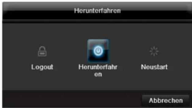
1.ДЯВIKHNoeHnBbI6epnteOnuIO BbIKHNoHTb nOaTBepnTe 3anpoc,HaxabA.Pnp6op6ydet BBIKHNoeH.
BoBpem npoecca BbIKIOueHnHaKmaiTe KnaBnSi
TenepbdoctaHbTe wTekep 6Ioka nItaHa.
2.ДЯб6LOKIPOBKN CnCTeMbI BbIbepnte CnMBON CnEBA 6LOKIPOBaTb.ПоЛьЗОВаTeЛьСКИ INHTepФeNc Tenepb 3a6NoKIPOBaH.уTo6bl nonactbB MeHIO Heo6xOIMO BBecTN napoiJb.
3. Дя Пеерукн Нжмite сиMHBOJ cnpaBa Пeepa3ka.Будт npoIN3BeDEHa Пeepa3ka np6opa.
BkIouHenepn6opa
HaKMITE KnaBnU OK n ydepknBaIte HaKaToB B TeueHne 5 cekyHd Ira HOBOrO BKIOuHEn npnbopa.
OtpaЖeHne cTaTyca
06uhe noJoxeHHa
CneyuOuee OtpaKeHne cTaTyca npOnHΦopMnpyIot Bac o pa6ooyem coCToHnn np6opa:
CBeToIOIObI cpeepnpi6opa
- Akcytneckne cnHnabbl
- RaPbIKn (3JIeMeHTbI INDnKauuN) Ha MOHInTope.
yKa3aHne
CneyuTe yka3aHnMaB O TDeIbHoN KpaTko INCTpyKuIN.
Инданкацnia Ha MOHTope
YcTpoIcTBo OTo6paKaet DaTy N BpeM, Ha3BaHne KaMepbl, a TaKke Ndet JIn 3aNcB.
- HenpepbHna 3aHncb: cmbBoR CnHero Zbeta
3aINcBpacNo3HaBaHnA DnXKeHn:CNMBON R KeNToro CBeta
HactpoJa cncTembl
HAcTpoek conpOBoXJaet Bac cKBO3b BCE Heo6xOaMbIe HAcTPOKn CnCTembl. NocJe 3TORO uΦpoBoi peKOpdep HAcTPOeH dIaNNu KOnTHPOJIA.

Yka3aHne
Bce DeTalbHbIe HAcTpOKn BbI HaNdTe B MeHIO np6opa, cm. O63Op Ha cTp.23.
Iocne nepBoro BKNHueHn NOBNTcBb16op 3bka:
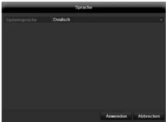
HactpoKa BbIXOa KaMepbl
BblMOKeTe npOn3BOOHTb BOCpOn3BeDeHne OndHOBpeMeHHo MaKc. no 16 kamepaB pexnme OTo6paXeHHa.
HacpoKa X 03haaET, yTo 3Ta KaMepa He NOKa3bIbAeTcR.
MeHIO KoHpUrypauny npaBnreT BcEMn HacTpoKAMn np6OpOB.

PpeynpeKdHne
MeHIO nIaHcTPOIK npaAMeTPOB KaMepbI (OSD-koHpIpyaun, pexm n3o6paKeHn, PTZ-KoHpIpyaun, DeTeKTop DnJxKeHn n T.d.) BHIMAHNE!
PocneIyOuEe N3MeHeHHe MoKeT npBecTn K noTepe daHHbIX!
BoBpEmI npoBOAnTe pe3epBHOe KOnnpoBaHne daHHbIX.
0630p
Co6IIOaTe HNCTpyKcUN yKa3aHnA dIeTeBbIX np6OpOB.
Bo3MOxHcOeDHHHe c HecKoJIbKIMn nepeKIOuHaTeMaMn/POyTepaMn/ToKAMn DocTyna. BpaHdMay3pbI nApYrne 3aunTHbIe nporpaMMbI MoryT hapuHTb pa60Tu CETn.

PpeynpeKdHne
Pn nCnoJb3OBAHm poyTepa ceTeBbIe KIneHTbl, a TaKKe peRNCtpaTOp, NOkNIOUaOTcK INTEpHety. HAO6OpOT.
Bo n36eXaHHe HecaHKUHOHPOBaHHOrO DoCTyNa n3BHe 06a3aTeJIbHo npMITE 3aUHTbIe MEPbl, nCNoJIb3yJ, HApPmep, 6paHdMay3p, n3MeHra napOl b I npTb!
KoHpyauncaTn
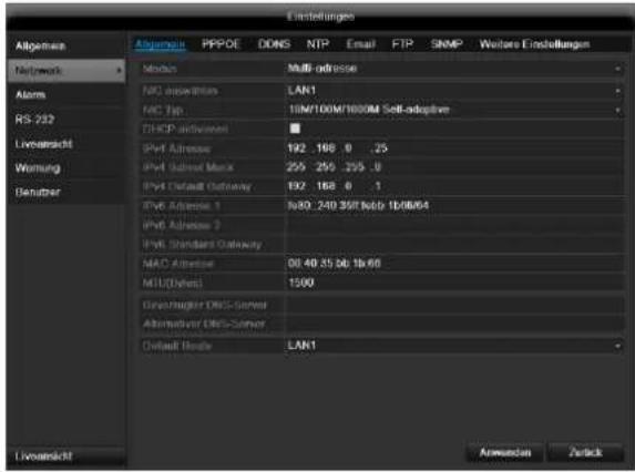
H3 coo6paXeHn COBMeCTHMOCtN NcNoJIb3yIte Email KIneHTbl, KOtOpbIe No3BOJIAOT yCTaHaBJIbBaTb DoCTyn NocpeDCTBOM SMTP.
SNMP
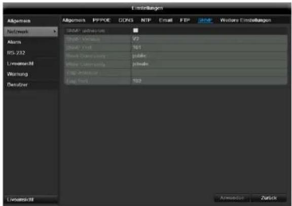
CoxpaHeHne N Bbl3OB IpeDyctaHOBKn
YcTaHOBka N Bbl3OB naTppyJe
- Co3daiTe HeckoIbKO npEduCTaHOBOK, UTo6bl NcnoJIb3OBAt bN x dIg IaTpIy.
- Μεικητης πο +ДЯ Bыбoga ПрedlyctahOBkn
4.Добавпдругп Прedlyстовки дян actpoкижелаemoro natpyл <|im_start|>assistant 1 - Μεικητηνοςυνόγν Bocnpoun3BedeHneДну NaTpyn.
Двнжени
B nyHKTe «Kamepa» Bbl6epnTe o6pa6aTbIbAembl KaHAn KamepbI.
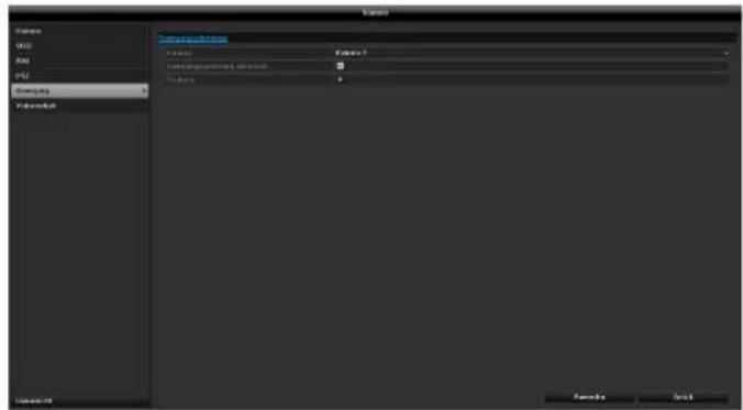
DienCTBnE
AKTNBnPoBaTb KaHa
UeKHyB NO «DeyCTBne» NOBnEeTcBKnJaKa
AknBaunKaHana(TolbKnPnTeKTopeBvXKeHn):
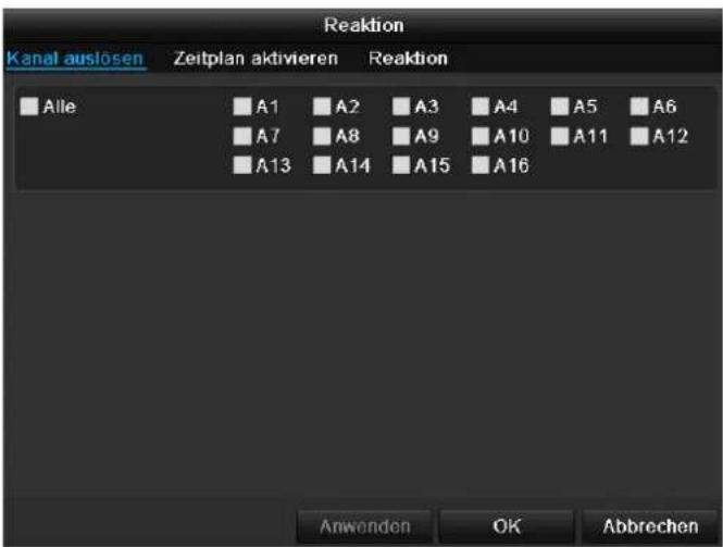
Bb6epnte OINH INH HeCKoNbKO KaHaJIOB, KOToPbIE B cnUyae TpeBOrn DOJIKNHbI AKTNBnPoBaTb JeIcTBne. IoTBePNTe HacTPOKn, UeIKHyB PpIMeHTb n NOKnHBTe MeHIO, HaxaB OK.
PacnncanHe
Bb6epnte BknaKy PaacncaHne.
YcTaHOBnTe B KaKoe BpEmHaCTPoEHHbIe B BKNaJaKe DeNCTBnEDeHCTBnA DOJXHbI 6bITb AKTNBnPOBaHbl.

- BbIbepeTe DeHb n ycTaHOBnTe paCnncaHne.
yKa3aHne
Дязэпссnomоью TeTeKTopaDbNKeHnHaCTpoIte pacncacHne B 3anncs(cM. cTp. 53).
yKa3aHne
MaKcHMaJIbHO MoXHo yCTaHOBnTb 8 BpeMeHHbIX cetOK, KaXdA c 00:00 - Do 00:00; BpeMeHHbIe OTpe3Kn B OTdeJIbHbIX BpeMeHHbIX CETkax He DOJNXbI NepeCeKaTbcr.
- BbI6epnteB KonnpoBaTb,doJxHa Jn HacTpOJa npImeHrTbcra KO BCEM dHram HeJeN n HAcTpOaM OTnycka.
- IoTBePnte HAcTpoKn, UeNkHyB PnpMeHHTb N OOKHBTe MeHIO, HAKAB OK.
DcCTBnE
Bb6epnte Bklaiky DeiCTBne.
3decb MOxHO HAcTpOHTb NOBeHHe peRnCTpaTopa B cnuyae ONpeJeHHoro CObItn (HaNPmep, npi DeTeKTope DnHexeHn), yCTaHOBnB COOTBeTCTByoUnn naXok.
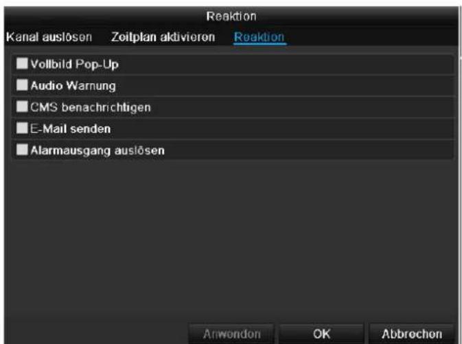
YcTaHOBnTe ranoKy Ha AKTINBnPoBaTa b JInHyO 3Ony.
1.CnmoBIOMbIKN BIDeJIHTe Do qetbipex oBnaCTe IINHOr 3OHbl.
2. BbI6epnte B KonnpoBaTb npIMeHnTb Jn HacTpOky dJIa BCex KaMep.
3. NpOITBepDnTe HAcTpoKn HaxKaTneM PnpMeHHTb N BblnTe n3 MeHIO HaxKaTneM OK.
KoHTpOJIb ca6oTaKa
B nyHKTe MeHIO «Kamepa» Bbl6epnte 6pa5aTbIaembl KaHaJ Kamepebl.
YcTaHOBIne raIOUky Ha AKTINBnPOBaTb KOHTpOJIb ca6oTaXa.
Pacnncanne
Bb6epnte BknaKy PacncaHne.
YcTaHOBNTe B KAKOE BpEMHaCTpoEHHbE B BKnAKe DeCTBneDeIeCTBnI DOJXHbI 6bItb AKTNBpuOBaHbI.
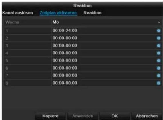
- BbIbepnte DeHb n yctaHOBnTe paCnncahHe.
i yKa3aHne
MaKcMajbHO MoXHO yCTaHOBnTB 8 BpeMeHHbIX ceTOK, KaJdA c 00:00 - Do 00:00; BpeMeHHbIe OTpe3KN B OTDeJIbHbIX BpeMeHHbIX CeTKaX He dONJHbI IpeceKaTbcra.
- Bb6epnteB KonnpoBaTb,doJxHa nn HacTroPk a npmeHrbcra KO BCEM dHram HeJeNn HAcTroPkam OTnycka.
- IoTBePnTe HAcTpoKn, UeIKNHyB PpIMHeHtB nOKnHbTe MeHIO, HaxkAB OK.
DcCTBnE
Bb6epnte Bknaiky DeiCTBne.
3decb MOxHO HAcTPONTb NOBeHHe peRnCTpaTopa B cnyuae ONpeJeHnHO co6bltna (Haepmep, npi DeTeKTope DnHexHna), yCTaHOBvB COOTBeTCTByuunn fJaxkok.

YCTaHOBtHe Ha KaKOM XeCTKOM DnCKe DoJXHbI 6bITb npOn3BeDeHa nepe3aNNc b6Onee n03dHx 3aNNcei.
MeHIO «OTnyck»
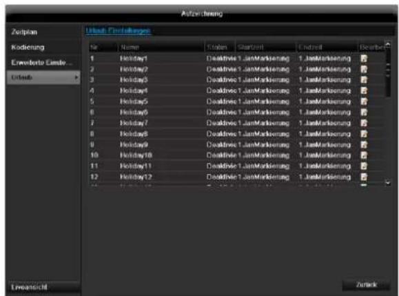
B noDMeHIO MOryT 6bITb yCTaHOBNeHbI 32 pa3NJuHbIX BapnaHTa HAcTpoKn BVdeO3aNcN Ha BpeM oTnycka IINI npa3dHKnOB.
IyctaHOBKn DaHHbIX Hactpoe KcJIKNHTe NO CmBOJy PedaTnpoBaTb.
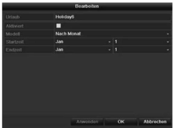
YcTaHOBka JecTKoro DnCKa
1.ИЗолупг Te np6op OT aJIeKtpocetn O TkpOte 3aunTHbI KOpNyc.
2. C6JIIOaIte npednncHnno OTbOJaUM 3JIeKTPoCTaTnuecknM 3apJam npu o6paueHnC 3JIeKTPnuecknM npnbopam. Y6eNTecb, yTO OHN 3a3EmJeHbI.
3.He OTKpbIbAte KOpNyc B NOMEueHnX C KOBpOBbIM NOKpbITHeM INI 3JNeKtpocTaTnueCKn 3apJxHeHHbIMN NOKpbITnMaN.
4. 136eraIte TeneCHoro KOHTAKTa CO BCEMN YACTaMn nnatbl.

PpeynpeKdHne
Ecny Bac Bo3HKnBONpOcbl K yka3aHnM
HHCTpyKuNN NJIN DaHHo INHOpMaun
HeoctatoUHO, o6paTntecb K Baewmy
CneuaNtCy no yctahOBke mOHTaxy.
5.YctaHOBNTe XeCTKIM NUCK I OBeCneYbTe HAdExHooCTb COeINHeHn.
6. Choba yctaHOBNTe KOpNc n noKNIouHt e CeTeBOe NITAHHe yCTpOHTBa.

Yka3aHne
Ecnj KecTkn Dnck He OTo6paKaetcra, npOBepbTe coeDInHeHne.
Bb6epnte MeHIO «HDD»ДЯ yctaHOBJENHaHCTpoekynpaBHeHnJ KecTKM DnCKOM.
IapametpbI ynpaBHeHЯ JecTkIM DnCKOM

CoCTOHNHe JecTKOrO DnCKa MOxHO pOBepNTb B MeHIO Texo6cnyKuBaHne. B nor-paJnx coXpaHReTcra HOpMaunr SMART (Self-Monitoring, Analysis and Reporting Technology).
ДяЗTORO OTKpoTe Jor-faHn BbINONHte NOnCK HΦopMaun/S.M.A.R.T. JKecTkN Dnck. HAcTpoKa CnHaJIOB PpeynpeXeHn JecTKOrO Dncka
3decb MoXHO 3aDaBaT cHnAbI npEynpeXeHnJ XeCTKOrO DNCKA, KOToPbIE 6ydyT COo6uAtb o6 Own6kax XeCTKOrO DNCKA.
Дяг STOrO OTKpoIe TpyHKT Texo6cnyxuBaHne B MeHIO HAcTpoE.K.
3aanncb naHnKn
3ainncb
HaKMTe KONky REC nI nepeiNTe B rIaBHOe MeHIO Ha 3aNNc b naHKn, yTO6bI 3aNyCTntb 3aNNcB n3o6paKeHna/BnDeo BpyHyIO.
BbIbepeIte noDMeHIO 3aIuNc.
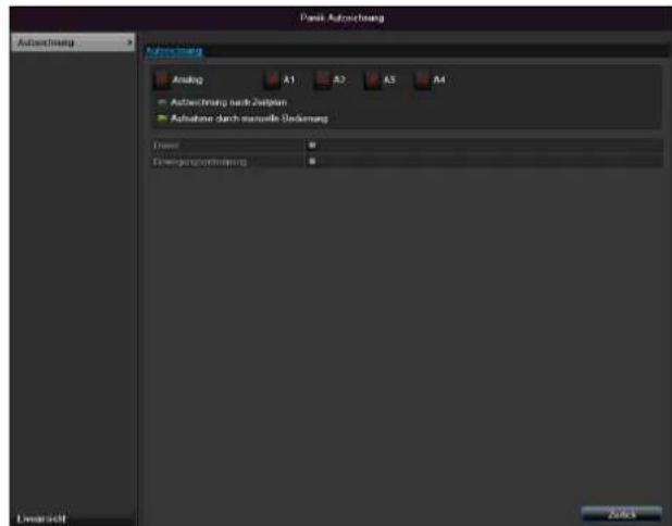
PpeBocnp.3aNcN /PpeTpeBOXHbIe 3aNcN MoTy6bITbTObKO npOCMOTpeHbIB Cnyae cdeJAHHOJTO TpeBOr3aNcN.
i
Yka3aHne
IopMeHIO IpoOOnJXnteNbHOCTb》I 《N3o6paXeHne》NdeHTnUHbI Nno3ToMy He npuBOaTcra 3Decb OTdJIbHO.
TexHnueckoe o6cnyxmbaHne
yKa3aHne
MeHcnyKNTIgTexO6cNyKbAHn np6opa ndoJIxHO IcNoIb3OBaTbC8 OblTHbIMIolb3OBaTeJEM.
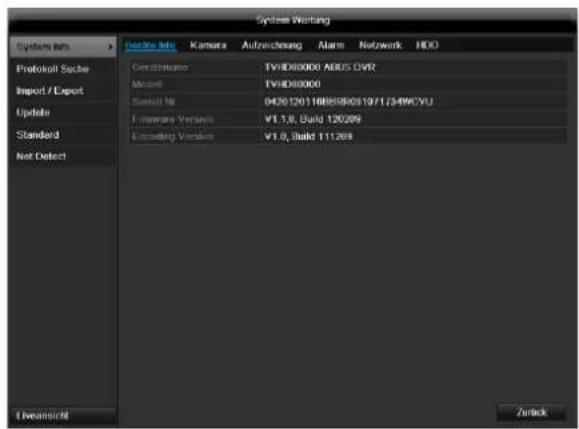
Pon3Becn BOCCTaHOBJHne CNTeMbI
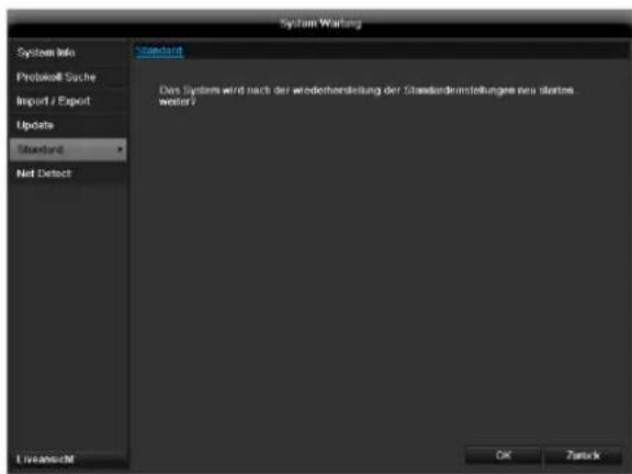

Yka3aHne
Pn daHOM npoecce HacTPOkN np6opa n3MeHOTcHa 3aBOckne (BocctahOBHeHne).

PpeynpckdneHc
Bce HacTropon, KOTopbIe Bby yCTaHOBuIN C MOMeHTa Nycka B 3KcNpyatauIO (KaMepbl, HacTroPkn 3anncn, PTZ, TpeBora n T.D.) 6ydyT ydaJeHb!
IpeDOTBpaTne IOTepIO daHHbIX, COXpAHN HacTpoKn. IIO OKOHuaHm npEydCTaHOBKn Bbl MOKeTe CHOBA CHTaTB IX.
Cetb
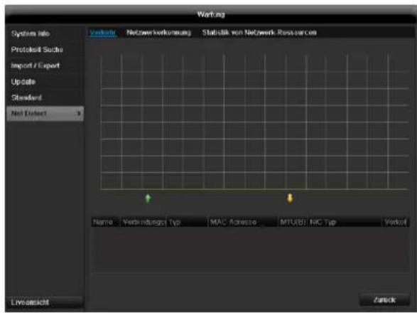

Yka3aHne
3decb OTo6paKaaeTcra HOpMaunO ceTeBOM DBXKeHH NHTeppeence.
Bknadka ceTeBaHarpy3ka
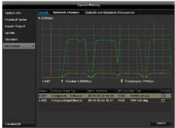
KoJIueCTBO nonyehHbIX npHraTbIX daHHbIX OTPaKaETcRpaΦnueckn.
B noJIe nOД rpaФИKOM B 3aBnCIMOCtN OT CeTeBbIX HAcTpoEk OTPpaxKaETcR COCTOHne INHΦOpMaunr O6 OdHOM, DBYxCeTeBbIX pa3beMax.
BknaKa PaCno3HaHne cTeN
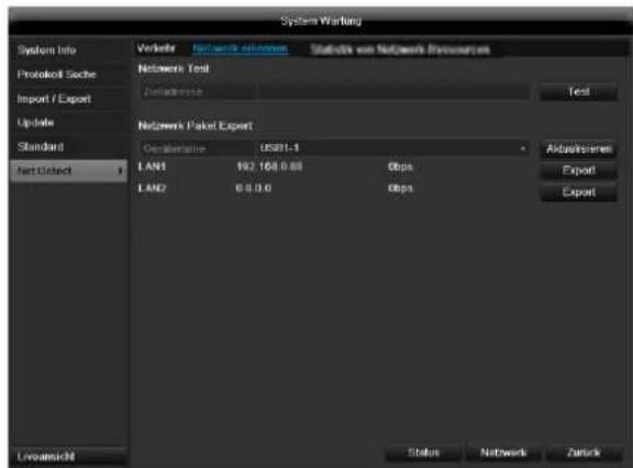
B «3aepkca cetn» Bbl MoxeTe («IpOINHROBaTb») npOBepntb coeunHeHne C npyum np6opom, Hapnpemekomnbtopeom. BBeDNTe cTeBOJ aDpc npOBepreMOROp60pa (hanpimep 192.168.0.25) n Haxmute PpoBepka.

HOpmaunO DByN npametpax OTo6paKaetc:
BknaKa CtaTnCTnKa ceTeBbIx pecypcoB
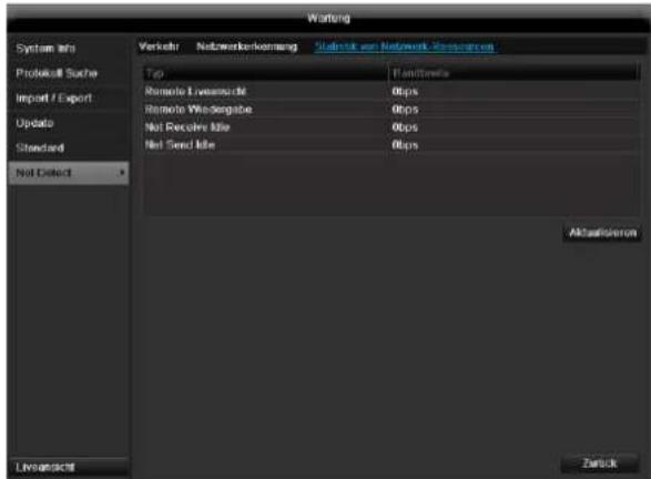
B daHHoB kNaIaKe OtpaKaETcra IcNoJIb3yEmble cTeBblpecypcbI yCTpOInCTBa.
IeJIKNyB no AkTyaJn3npoBaTb MoXHO 06HOBNTb daHHble.
3aBepseHne pa6oTbI
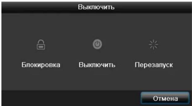
i
Yka3aHne
Bb6epnte cyHKnIO «EloKpObaTb» dna 6IOKpOBKn MeHIO ynpabHeH.
BbI6epnteФyHKnIO《BbIKNIOHTb》ДЯ BBKIIHOUeHnYcTPOINCTBa.
Bb6epnte cyHKcHIO 《Pepe3arpy3ka》I npoBeHnnpocecca nepe3arpy3kn (BbIKNoyeHne n NOBtOphoe BKnOyeHne).
YcTpaHHeHHeNCnPaBHOCTeI
Ipeed Bb3OBOM CepBnCHoN cnyk6bl npouTIne cJeDyUOuNe yKa3aHnno OnpedeJIeHNIO BO3MOXHOI npuHbI HncnPabHocTu.
| Héncnравноctь | Причinhа | Реценье |
| ОсутствуET зелковпатие. | He полкюуне сетево кабелBSeTeВоВ bByklnIOUATEЛ bHaxODITcBbNoLOXeHIMN «ВыкNs」.Штесгая розетka He npobodNTэл ektrpuecTBo. | Болee пIoTHO полкюочte кабелКposztke.PpeCTabte сетево bByklnIOUATelB noLOXeHINe «ВыкNs」.ПоLDKIOUHTe,При необхODIMOCtN,дугоиprinbopКштесгон розетke. |
| ОсутствуET ИЗбражене. | Зкразн He полкюуне дlya поучениBVideocnIHana.BiJdeo-Kaбел nobкюочen He nILOTOH.NoJIOUCHHb moHITOP BByklnIOUeH.I | Выберп Te prabNVblh b pexim noIyчENn BVideocnIHana ПОКа на PericTpatope He noJYBtCg IN3O6PaxGEHne.ПлOTH NOДКIOUChTE BVideo-KaбELB.BKIOUCHTe MOHITOp. |
| Het 3byka. | Aydno-Kabel nobKIOUChEN He nILOTOH.NoKlIOUHbte c noMOuCbU o aYdno-KabelaPrnOBpbl He BkIOUeHb.I.Aydno-Kabel nobPexdien. | ПлOTH NOДКIOUChTE ayDINO-KabELB.BKIOUCHTe coeDiNeHbte c noMOuCbU OdaHORO kabela PrnOBpbl.ЗамeHITe KabeIb. |
| ЖecTKДДСНК He pa60taet. | CoedinHITbHbkeJI noKIOUChE hHe nILOTOH.XeCTKДДСНК noBpEXdEN iIи He COBMeCTMmC smCTeMoi. | ПлOTH NOДКIOUChTE aYdINO-KabELN.BKIOUCHTe coeDiNeHbte c noMOuCbU OdaHORO kabela PrnOBpbl.ЗамeHITe KabeIb. |
| USB-pa3bem He pa60taet. | ПоДерЖka uystpoiSTBa He obecneuHbAetcra.NIcNoJIb3yETc USB-pa3BETBvItelb. | ПоДКIOUHTb KORpeKTbHb HocnteIb c nopTOM USB 2.0.He noKIOUChAE USB HocnteIb habpЯMuIb. |
| Сeteво Достун Hevo3MoJeuH. | Слобoe noKIOUChENe ceteBOrO kabela.OShn6ka NaCTpoeK CETN(DHCP, IP-aIpec n T.D.). | Вставы Te сeteBOw kabela.Proberbte iIи nCnpabBe TE konФИурацMuOcTe, CM. ctr. 41. |
| He pa60taet nbIbTy uypaBLeHn. | Батарen BCTabLHbI He npabVilbHo (+,-) iIpi prazdINICb.I | ПрОзВeДиTe 3aMehу bSaparay Na HOBsIe.DЯу ураловеля priobopom c noMOuCbIpyNbTa yCTaHOBt eIx c noMOuCbI duTchika pyNbTa ynpaBLeHnHa pri6Ope.IIcNoIb3yIe TnybT npaBLeHnHa na pri6Ope. |
| ПульТ ураловеля уdanielen OT pericntparota.P.Mexdy nbIbTom uypaBLeHnI bVideoperincTpaTOpom haxODITcRпряTCTBVE.CsIIuKOM cInlbHaj rapKoCTb iIи Me7aet cbETIbOMHeusceIeHTbIX Trp6ok? | ИсрОьЗуITE ngIbTу npaBLeHnHa na pacSTOnHIM 7 MeTPOB.YdAnITE pripeTCTBVE.UMeHbIte yapKoCTb CBetaIbOMHeusceHTbIX Trp6ok. | |
| ЗапSCb Hevo3MoJoxHa. | ЖeSTKДДСТ(HDD) оTCYCTBvET iIи He yCTaHOBnE. | УstановпЕ и HabToite яжettingкдИck. |
| Внзаимоe Вькlioquенепriбopa. | TemnepaTyaВHуТРи ріnbopa сclnskomВblcoká. | ОчирTe ріnbop iIи уdaniTe BCEmeSHAJOUmeBEHTINIAZIM innpeDmetbl. |
OuNTka yCTpoIcTba n yXoI
yka3aHne
- Ipo6op He Tpe6yeT Texo6cIyKuBaHnA.
- 06eperaTe yctpOCTBO OT nonadHnB Hero nbIn, rpa3n n BnaR.
TexHnueckne XapaKTepncTnKn
Bo3MOxHO HaJIyue TeXHYeCKNX I3MeHeHn OoHN6OK.
| BNC + VGA | HDMI only | VGA only | BNC only | HDMI + VGA |
| ✓ | ✓ | ✓ | ✓ | ✓ |
Ytuln3aun
CcbIka Ha dInpeKTHBy EC no yTnIIN3aunn CTaporo 3JeKTPnueckoro n 3JeKTPoHnHO o6OpyDoBaHn.
B cBra3n C oxpaoH oukyaHoue CpeDb np6op no OKOHuaHn Cpoka erO cnJyK6b1 MoKeT 6bITb yTuIN3OBaH OTJeJIbHO OT 6bITOBbIX OTXODOB. YTuIN3aunr MoKeT OcUeCTBnTbcS cheE3 oFNUaJIbHbIe NyHKtbl npHeMa B BaWe CTpaHe. Co6IIOaIte MeCThBi e npEdncaHn rno yTuIN3aun MATEpnaIob.

ПюиЗБeДTe yтлИзацию устpoиCTBa corIacHo dinpeKtInBe 2002/96/EC - WEEE (Waste Electrical and Electronic Equipment) no ytлИзаци nOtxoIOB 3JIeKtpuYeCKOrO n 3JIeKtpoHnOro obopydOBaHnY. EcIn y Bac Bo3нКЛь BOnpocbl, obpaTntecb B MeCThIbe opraHbI ynpaBLeHnY. BoJee noIapO6HyIO INΦopMaциIO O nyHkTax npHeMa cTaporo obopydOBaHnry Bbl nOpyUte B MeCThBIXoprAHAx ynpaBLeHnY, MeCThBIX ytлИзИруQUx KOMпaHnx IINy y Baшero dInepa.
CcbIka Ha dIpuKeTnBy EC RoHS
Pn6Op COOTBeTCTByeT DnpeKtNBe RoHS.
CobnOeHne DnpeKtNBb EC RoHS 03Haayet, YTO npOdyKT nnn DeTaNb CopeKNT BeuecTBA, DOJRA KOHcHTpaunn KOTOpbIX BROMoREHHbIX MaTePnaJax He npReBbIaeeT MaKcMAmbHO DoNyCTMbI yPoBeH. HNaYe, DaHHoe BeuecTBO NCKIOUyeHo n3 DnpeKtNBb RoHS.
a) 0,1% CBNHua (B 3aBNCIMOCTN OT BEca),
b) pT Tb,
c)JIECTINBaIeHTHbI XpOM,
d) noJin6pomnpoBaHHbI 6nΦeHnI n noJin6pomnpoBaHHbI dNΦeHNIOBbI 3Φnp,
e) 0.01% kaДмья (В заимости OT Beca).
Tnoccapn
IcnoJb3yeMbIe TepMnHbI
1080P:
HDTV-BuDaeocnHan c 1080 nKcIaMn nporpeccNBbIM IpOCMTpOM.
16:9
KInHoOpnEHTnpOBaHHoe COoTHoWeHne CTOpOH WInpOKo3KpaHHoro DnCnIe.
Диагональ n3o6paxeHHa
Yka3aHne pa3Mepa DnCnJIe: pacCTOHaHE MExdY JIEBbIM HxHM IpaBbIM BepXHM yIOM - B dIOImax ININ caHTmETpax.
6pay3ep
Pporpamma nI npocmotpa Be6-caITOB B cETN INHTepHET.
CIF
«Common Intermediate Format».
I3haaJIbHO npedHa3HauJcA dIe nepeBoDa fOpMaTa PAL B NTSC cTaNdApT. CIF COOTBeTCTByET BnDeo- pa3peSeHnIO 352 x 288 nKCeJe, 2 CIF 704 x 288 nKCeJe, 4 CIF 704 x 576 nKCeJe.
CINCH
PacnpoctpaHEnHbTn aHaNoROBbIx aydno n BuDeocrHaJIOB FBAS.
DDNS
Диhamnueckn DNS
Cetebocepbuc,coepkaunIP-apeca KnneHToB B 6a3e daHHbix npOn3BOJauu nX o6HOBHeHne.
DHCP
«Dynamic Host Configuration Protocol» - npotoKoI DInHaMnueckoHacTpOuKn y3na
CTeBOI npOTOKOJI, NO3BOJIAUHm ABTomATnueckn INHTepnpoBaTb yCTpOiCTBa (KHeHTbl) B cyuEcTByIOuNe cETn. Pn 3OM cepBep DHCP (Hanpimep NHTpeHetPOyTep) ABtomATnueckn npncBaanBaET IP-aDpeca, Macky cETn, uIO3, cepBep DNS un cepBep WINS. Co CTOpOHbl KnEHTa Heo6XODIma aKTINBaunr ABtomATnueckoro nOnyuHn r IP-aDpeca.
DomeH
Домены сныкатдяиdeHTNФИКAUIN INHTepHET-CAITOB (hanpimep, www.abus-sc.de).
DyaanbHbI noTOK
DyaIbHbI NOtOK -Ha3BaHHe Ipouecca nepeaun BundeO.
PpOcXoJIT 3aIncB BBICOKom pa3peuHenn I
pepaA b 60ee Hn3KOM pa3peuHenn (Ha npimep
yepe3 cetb).
NVR
LHpOBn BndeoperncpaTOp - np6op dna 3aHcnpa3nHbIX BnDeo n ayDnO-NCToHKnOB (aHaNOrOBbI, LHpOBn). DaHHbIe KOMPmMpyOTc DnA 3aHcN I COxpaHJOTc, HApIMep, Ha JecTkN DNCK.
NTC
IOnHbI UBeTHoTeJeBn3NoHHbI CnHaI (NTC).
IpocToB BapNaHT BnDeOcNHaJIOB, TaKke Ha3bBaEmbI KOMnO3nTHbIM CnHaJOM. KaYeCTBO N3o6paKeHnA OTHOCuTeJIbHO Hn3Koe.
H.264
(MPEG-4AVC); cTaNapT dIy BbICOKO KOMnpecnn BnDeocnHaIOB. IcNoIb3yETc TaKKe dIy DnCKOB Blu-Ray nJIn cnCTem BnDeOKOHΦepenucBra3n.
HDD
«Hard Disk Drive» - «жecткий дисн (нakони teь на MaHTHbIX dNCKax).
LHpOBoe 3aONMaHOuCe yCTPOINCTBO KOMNbHTepOB IN CeTeBbIX BnDeOpErNCtPaTOPoB.
Гирабайт
Eduina u3mepeHnKoJIueCTBa HOpMaunIINHocTeJeuHOpMaun(HDD,USB,SD/MMC-kaPT).
HDVR
IbnpHbBnBnEopernctpaTOp,BnEopernctpaTOp dna 3aHNCN NOMOuBHO aHaNoROBbIX NCeTBbIX KaMep.
http
"Hypertext Transfer Protokoll" npotokon npepaun rnepekcta.
Ipouecc nepedaun daHbix uepe3 cetn. PnpmeHareTcB OCHOBHOM dnn npocmOTpa caITOB BVHTepHeT- 6pay3epe.
Yepecctpouha pa3BepTka
MeToD TeNeBn3NoHHo pa3BepTKn.
IP-Adpec
AmpcB KOMnbIePepHO CEtn. OChOBaH Ha Internet Protocol (IP), KOTOpbI npCBAuBaET ceTeBbIM ycTpoiCTBaM ONpeJeHHeIe aDpeca n, TaKIM o6pa3OM, DeJaet IX DOCTyINhBIMN.
JPEG
Ipouecc KOMnpeccnn DnA fOtorpaΦn C MaIbIMn notepAmN.BoIbUnHCTBO uDpOBoBix kamep coXpaHHT fOtorpaΦn BΦopMaTe JPEG.
MPEG
CokpaueHne dIa Moving Picture Experts Group.
MexdynapoHbI cTaNapr InKOMPeccN uΦpOBoi, BnDeo n ayDnO nHΦopMaun. Ha HeKOTOpbIX DVD KOMPnMnPOBaHHbI n 3aNcaHbI uΦpOBbie ayDnOCnHaJIbI daHHoro φopMaTa.
NTP
"Network Time Protocol"
Ipouecc cnHxpoHn3aun yacOB uepe3 INHTepHeT-ceTN. A
takke SNTP (Simple Network Time Protokoll),
npedctablaioi 6oee ynpoueHHy0 fOpmy.
NTSC
CTaHdApTHa cNCTeMa CBETHO TTeBnDEHb B CSHA.
IMeET HeKOTOpbIe OTJNUHr OT EBPOneCKo nCtEmbl PAL.KaDp NTSC coCTOHT Bcero n3 525 cTPOk,480 n3 KOtOpbIX BnIMMbIe.BcekyNDy OTPaKaIOTC60
m3o6paXeHn CTpeOpnapbl. IOn CpABHeHIO c PAL
CNCTema B 6oJIbWei CTeHn NODBePKeHa cBeTOBOMy
NCKaXeHIO.
PAL
«Phase Alternating Line» - ebponencka cnCTema UBeTHoro TeNeBnDEHn; nCOnb3yeT 576 BnDnMbIX CTPOK, BMeCTe C NcNoJIb3yEmbIMN dIra CnHaJIOB ynpabJeHn CTpOKAMn CoCTaBnEeT KaIp I3 625 CTPOK. B CEkyNDy OTPaKaIoTc4 50 n3O6paXeHn CTpeOpApbl. PonoXeHne no pa3e CnHaIa n3O6paXeHn CmHReTc8 OT CTPOK IN CTPOKe.
PanaheIb
TePMnIgONsCaHnBHyTppeHHeN CTOpOHJI NIOCKORO dncnner (KK- nnnnna3MeHHbI naHeN).
#
IepcoHaJIbHbI KOMMbIOTep MOKeT NcNoJIb3OBaTbcB KaueCTBe MeCTa INcTaHcIOHO 3aNpOca C NOMoUb COBMeCTHO NOCTaBIAReMOro IporpaMMHO o6ecneueHn JIn6o C NMOuCbIO 6pay3epa.
ПикSEL
"Picture in Picture"
CokpaueHne dnyHKunn «N3o6paxeHnB n3o6paxeHn》,6naorapKOTopoHa 3kpane OHOBpeMeHHO NOBnHTcraDbA NCTOCHNA CnHAnOB. BTOPOI NCTOCHNK CnHana HAKNaDbIbAetc Ha nepBbI.
PPPoE
«PPP over Ethernet» (Point-toPoint-Protokoll)
Ppoecnpeepaun daHHbIX uepe3 cetb, nCNoNb3yeTcnn yCTaHOBHeHn COeHNHeHn C Bbl6paHHbIMn COeHNHeHnMn, KOtOpIe HapnpMEp nCNOlb3yOTc npn ADSL-noKluOeHn.
PporpeccnBna pa3BepTka
OTo6paXeHne n3o6paXeHnI, npN KOtOpOM npOnCXoDnT PocNeIOBaTeNbHoe OTo6paXeHne BCex CtpOK KaDpa B IpoTnBOBec YpeecCTpOuHoN pa3BepTke.
PTZ
Пановамиpoване,нaklioн,уBELИЧЕпдЯ MOTOPИЗЮВаHHbIX KAMeP.
RTSP
"Real Time Streaming Protocol, RTSP"
CeteBOn npToKoJ dIy ynpaBneHn noCToHHoI nepeDaueNnotoka nn nporpaMMamu uepe3 IP-6a3npoBaHHbIe cETn.
SNMP
«Simple Network Management Protocol»
Cetebon npotokon, kotopb pyerynpye T coo6ueneMekdy Ha6nOdaembIMN yCTpOINCTBAMN u CEHTPOMHa6nOdeHNA. C COOTBEcTCTBYUQNM pOrpaMMbIM o6ecneHMe MOnKeT NcNoB3OBaTBcRdIy Ha6nOdeHNA 3a cTaTycom BnDeOpErNCtpaun.
USB
Universal Serial Bus
CepnHoe coeINHeHne sIHc pa3bEmOM, HapnpMep c HocnteJIaMn daHHbIX, BO Bpem TaKyupeN 3KcnIyatauN. MAcC. nCNoB3yEmbI o6bEm daHHbIX y USB 2.0: npm. 320 M6nt/c (npm. 40 MB/c).
VGA
OBHHTpeHHem XeCTKOM DnCKe
BHyTpEHn JxecTk nDnCK (HDD) yUbCTBnTeJEn K n3MeHeHnM. Ipon3BOJnte UnpaBHeNyycTPOIcTBOM B COOTBeTCTBnC O CNeDuOuIMN INCHtpKUINrMBO n36ExKaHne OUn6Kn XeCTKO rDnCKa. BaxHbIe 3aIncn DOJnxHbI 6bITb COxpaHeHbI Ha BHeuHIX HocHTeJAX BO n36ExKaHne HeoXnDaHHoN IOTePn DaHHbIX.
i
Yka3aHne
He nepeBnraIte np6Op BO BpeM 3KcnnyatauN.
Bnara BHytpn npnbopa moKeT KOHDeHCnPOBaTbCn n pNBOuNTb K HApyHeHIO cyHKn JKeCTKOrO dNcKa.
3anpeaetcBbItacknBaTb WTekep n3 cetn nn npekpaatb noaay 3neKtpoNTaHna yepe3 npedoxpahnteJb.
He nepeBnraTe np6op HenocepctBeHNO nocJe erO BbIKJIOueHn. JIa nepeBnxKeHn np6opa BbINOHNTe cneDyUoune warn:
- Nocne oTo6paKeHn coo6uEHH BbIKn. (Dncnne ycToPOiCTBa) noOxDNte 2 MmHyTbI.
- BbItaunTe wTekep.
3.Переметитей пибор.
Bpe3yIbTaTe c6oR nITaHnB BpEmr 3Kcnnyatauyn yCtpoiCTBa MOrY 6bITb yTeprHbI daHHbIe Ha JecTKOM dncke. IcnoNb3yIte N5P!
-KeCTKn DnCK OueHb CyBCTBNTeJIeH. HeaIeXaUee IcnoJb3OBAHne IIN HeoDxOJaAa CpeDa IJRA 3KcNpyaTauN JECTKOrO DnCKa Ha npOTJKeHn HecKOJIbKIX IET MOrYT NOBPeDntb erO. PpI3HaKaMn 3TOrO YBnIeTCra HEoXuDaHHa OCTaHOBka BOCpON3BeDeHn N BuIMMbI Ha n3O6paKeHn 3ΦΦeKT Mo3aIKN. PpI3HaKOB DeΦeKta JECTKOrO DnCKa Pn DaHbIX ObCToRtBCTBax Het.
-Пидфсгт ВОсрпОЗБЕДЕНe 3aINCEHbO3MOxHNo.ВданHOM cIyuae Heo6xOДIMo3aMeHHTb JecTKnДИСК.
ABUS
4/8/16-kaHaJIbHbI aHaIoroBOUcnpoBoB vndeOpErnctpaTop
TVVR41200 / TVVR41210 / TVVR41220
Ppoun3BODnteNb
86444 Affing (Germany
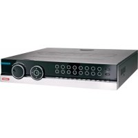
- ABUS 4/8/16-Kanal 650 TVL Realtime Digitalrekorder TVVR41200 / TVVR41210 / TVVR41220
- Deutsch
- Français
- VGA-Monitor angeschlüssen
- Entsorgen
- Device overview
- Note
- System operation
- General information
- Connections on the rear of the device
- Mouse operation
- Contents
- Quick guide
- Before you start
- Installing the HDD
- Warning
- Establishing the connections
- Configuring the device
- Important safety information
- Explanation of symbols
- Symbol Signal word Meaning
- Proper use
- Power supply
- Overloading / overvoltage
- Cables
- Installation location / operating environment
- Ensure the following:
- Remote control
- Care and maintenance
- Accessories
- Putting into operation
- Children and the device
- Introduction
- This device complies with the requirements of the applicable EU directives.
- Disclaimer
- Unpacking the device
- Scope of delivery
- On-screen keyboard
- Starting the device
- Important
- Switching off, locking and rebooting the device
- Switching on the device
- Status displays
- i Note
- Display on the monitor
- Setup wizard
- Setting up the system
- Setting up the administrator
- Time / Date
- Network Settings
- HDD Management
- Camera recording
- Live view
- Overview
- Status symbols
- Pop-up menu for mouse operation
- Selection bar in the camera image
- Settings
- Note VGA monitor connected:
- No HDMI monitor connected
- Setting the camera output
- Playback
- Playback screen
- Using the control panel
- Main menu
- Menu overview
- Configuration
- Network configuration
- Terms and definitions
- Network layout
- NTP
- SNMP
- User
- Permission
- Camera
- OSD
- Image
- PTZ
- Saving and retrieving presets
- Setting up and calling up patrols
- Motion
- Handling
- Trigger Channel
- Armin Schedule
- Private Zone
- Tamper monitoring
- Video signal loss
- Click on the TAB Handling.
- Record
- Setting up
- Schedule
- Application example
- Encoding
- HDD
- HDDs
- HDD Management parameters
- HDD settings of the cameras
- Mode: Storage
- S.M.A.R.T.
- Checking the HDD status
- Panic recording
- Recording
- Event
- Video Export
- Duration
- Event (event type 'Motion')
- Maintenance
- System Info
- Log Search
- Import/Export
- i
- Upgrade
- Default
- Network
- TAB network load
- Troubleshooting
- Device cleaning and care
- Technical data
- HDD storage capacity
- Overview monitor output combination
- Disposal
- Information on the EU directive on waste electrical and electronic equipment
- Information on handling batteries
- Important information on disposing of batteries
- Information on the European RoHS directive
- Glossary
- Overview of specialist terms
- Dual Stream
- DVR
- H.264
- GIGABYTE
- HDVR
- http
- INTERLACED
- IP address
- JPEG
- MPEG
- NTSC
- PAL
- PANEL
- PC
- Pixel
- PIP
- PPPoE
- PROGRESSIVE
- RESOLUTION
- SCREEN SIZE
- USB
- VGA
- ZOLL (inches)
- Internal HDD
- ABUS 4/8/16-channel analog digital recorder
- ABUS 4/8/16-kanaals 650 TVL realtime digitale recorder TVVR41200 / TVVR41210 / TVVR41220
- Afvoeren
- Surcharge/surtension
- Indhold
- Installation at hardisken
- Advarsel
- Henvisning
- Bortskaffelse
- HDMI/VGA
- Utylizacja
- Iopknoyehne
- Yka3aHne
- KoHcHpyaun npn6opa
- i yKa3aHne
- Baxhblc yka3aHnno TeXnke 6e3OnaCHOCTN
- Onncahne cIMBOJIOB
- 3JIeKTpOnuTaHne
- PpeynpeKdeneHc
- PpeynpeKdHne
- Peperpy3ka/PepeHanpJxKeHne
- Ka6eJb
- MecTo yCTaHOBKn/YcNoBn3KcnIpyTaun
- TexHnueckoe o6cnykBaHne n yXoD
- BbOdB3Kcnnyatauio
- PpeynpeKdeneH
- PpeynpeKdneHc
- Дети
- BVeJeHne
- NCKIIOUeHne OTBeTCTBeHHOCTn
- O6uHa HΦopMaucnA
- PacnaKOBka
- Obem noctabkn
- KnaBnata mOnHTopa
- BkIoueHne np6opa
- BHHMaHHe!
- BbIKIIOUeHHe, 6IOKIpOBKa, nepe3arpy3Ka np6opa
- BkIouHenepn6opa
- OtpaЖeHne cTaTyca
- 06uhe noJoxeHHa
- Инданкацnia Ha MOHTope
- HactpoJa cncTembl
- HactpoKa BbIXOa KaMepbl
- KoHpyauncaTn
- CoxpaHeHne N Bbl3OB IpeDyctaHOBKn
- YcTaHOBka N Bbl3OB naTppyJe
- Двнжени
- DienCTBnE
- AKTNBnPoBaTb KaHa
- PacnncanHe
- DcCTBnE
- KoHTpOJIb ca6oTaKa
- Pacnncanne
- MeHIO «OTnyck»
- YcTaHOBka JecTKoro DnCKa
- IapametpbI ynpaBHeHЯ JecTkIM DnCKOM
- 3aanncb naHnKn
- 3ainncb
- TexHnueckoe o6cnyxmbaHne
- PpeynpckdneHc
- Cetb
- Bknadka ceTeBaHarpy3ka
- BknaKa PaCno3HaHne cTeN
- BknaKa CtaTnCTnKa ceTeBbIx pecypcoB
- 3aBepseHne pa6oTbI
- YcTpaHHeHHeNCnPaBHOCTeI
- OuNTka yCTpoIcTba n yXoI
- TexHnueckne XapaKTepncTnKn
- Ytuln3aun
- CcbIka Ha dInpeKTHBy EC no yTnIIN3aunn CTaporo 3JeKTPnueckoro n 3JeKTPoHnHO o6OpyDoBaHn.
- CcbIka Ha dIpuKeTnBy EC RoHS
- Tnoccapn
- IcnoJb3yeMbIe TepMnHbI
- 1080P:
- 16:9
- Диагональ n3o6paxeHHa
- 6pay3ep
- CIF
- CINCH
- DDNS
- DHCP
- DomeH
- DyaanbHbI noTOK
- NVR
- NTC
- Гирабайт
- Yepecctpouha pa3BepTka
- IP-Adpec
- PanaheIb
- #
- ПикSEL
- PporpeccnBna pa3BepTka
- RTSP
- OBHHTpeHHem XeCTKOM DnCKe
- ABUS
- 4/8/16-kaHaJIbHbI aHaIoroBOUcnpoBoB vndeOpErnctpaTop
Brand : ABUS
Model : TVVR41210
Category : Voice recorder