RD6506 - Receiver SHERWOOD - Free user manual and instructions
Find the device manual for free RD6506 SHERWOOD in PDF.
User questions about RD6506 SHERWOOD
0 question about this device. Answer the ones you know or ask your own.
Ask a new question about this device
Download the instructions for your Receiver in PDF format for free! Find your manual RD6506 - SHERWOOD and take your electronic device back in hand. On this page are published all the documents necessary for the use of your device. RD6506 by SHERWOOD.
USER MANUAL RD6506 SHERWOOD
This symbol is intended to alert the user to the presence of uninsulated "dangerous voltage" within the product's enclosure that may be of sufficient magnitude to constitute a risk of electric shock to persons.

This symbol is intended to alert the user to the presence of important operating and maintenance (servicing) instructions in the literature accompanying the appliance.
WARNING: TO REDUCE THE RISK OF FIRE OR ELECTRIC SHOCK, DO NOT EXPOSE THIS APPLIANCE TO RAIN OR MOISTURE.
Caution regarding installation
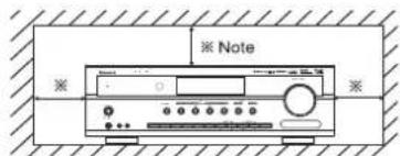
Note : For heat dispersal, do not install this unit in a confined space such as a bookcase or similar enclosure. Be sure to leave a space around this unit equal to, or greater than, shown below. Left, right and rear sides : 20 cm, top side : 40 cm
text_image
※ Note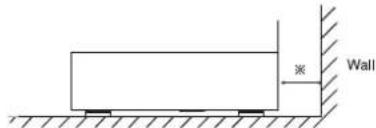
text_image
Wall ※Do not block ventilation openings or stack other equipment on the top.
FOR YOUR SAFETY
| EUROPE AUSTRALIA | 220 V-240 V | Units shipped to Australia are designed for operation on 230 V AC only.To ensure safe operation, the three-pin plug supplied must be inserted only into a standard three-pin power point which is effectively earthed through the normal household wiring. Extension cords used with the equipment must be three-core and be correctly wired to provide connection to earth.Improper extension cords are a major cause of fatalities. The fact that the equipment operates satisfactorily does not imply that the power point is earthed and that the installation is completely safe. For your safety, if in any doubt about the effective earthing of the power point, consult a qualified electrician.PAN-EUROPEAN UNIFIED VOLTAGEAll units are suitable for use on supplies 220-240 V AC. |
CAUTION
- Leave a space around the unit for sufficient ventilation.
- Avoid installation in extremely hot or cold locations, or in an area that is exposed to direct sunlight or heating equipment.
- Keep the unit free from moisture, water, and dust.
- Do not let foreign objects in the unit.
- The ventilation should not be impeded by covering the ventilation openings with items, such as newspapers, table-cloths, curtains, etc.
- No naked flame sources, such as lighted candles, should be placed on the unit.
- Please be care the environmental aspects of battery disposal.
•The unit shall not be exposed to dripping or splashing for use. - No objects filled with liquids, such as vases, shall be placed on the unit.
- Do not let insecticides, benzene, and thinner come in contact with the set.
- Never disassemble or modify the unit in any way.
■Notes on the AC power cord and the wall outlet. - The unit is not disconnected from the AC power source(mains) as long as it is connected to the wall outlet, even if the unit has been turned off.
• To completely disconnect this product from the mains, disconnect the plug from the wall socket outlet. - When setting up this product, make sure that the AC outlet you are using is easily accessible.
- Disconnect the plug from the wall outlet when not using the unit for long periods of time.


Pb
Information for Users on Collection and Disposal of Old Equipment and used Batteries
These symbols on the products, packaging, and/or accompanying documents mean that used electrical and electronic products and batteries should not be mixed with general household waste. For proper treatment, recovery and recycling of old products and used batteries, please take them to applicable collection points, in accordance with your national legislation.
By disposing of these products and batteries correctly, you will help to save valuable resources and prevent any potential negative effects on human health and the environment which could otherwise arise from inappropriate waste handling.
For more information about collection and recycling of old products and batteries, please contact your local municipality, your waste disposal service or the point of sale where you purchased the items.
[Information on Disposal in other Countries outside the European Union]
These symbols are only valid in the European Union. If you wish to discard these items, please contact your local authorities or dealer and ask for the correct method of disposal.
Note for the battery symbol (bottom two symbol examples): The sign Pb below the symbol for batteries indicates that this batteries contains lead.
CONTENTS
Introduction
- READ THIS BEFORE OPERATING YOUR UNIT | 2
System Connections | 4
Front Panel Controls | 10
Remote Controls | 12
- LISTENING TO RDS BROADCASTS(FM ONLY) | 24 (RDS Tuner(Regional Option for some countries in Europe, etc.))
- RECORDING | 26
• OTHER FUNCTIONS | 27
• CONFIRMING THE HDMI FUNCTION | 28
System Setup | 29
- SETTING THE SYSTEM | 31
- SETTING THE INPUT | 33
- SETTING THE SPEAKER SETUP | 34
- SETTING THE CH LEVEL | 38
- SETTING THE PARAMETER | 40
- SETTING THE HDMI | 42
Troubleshooting Guide | 44
Specifications | 45
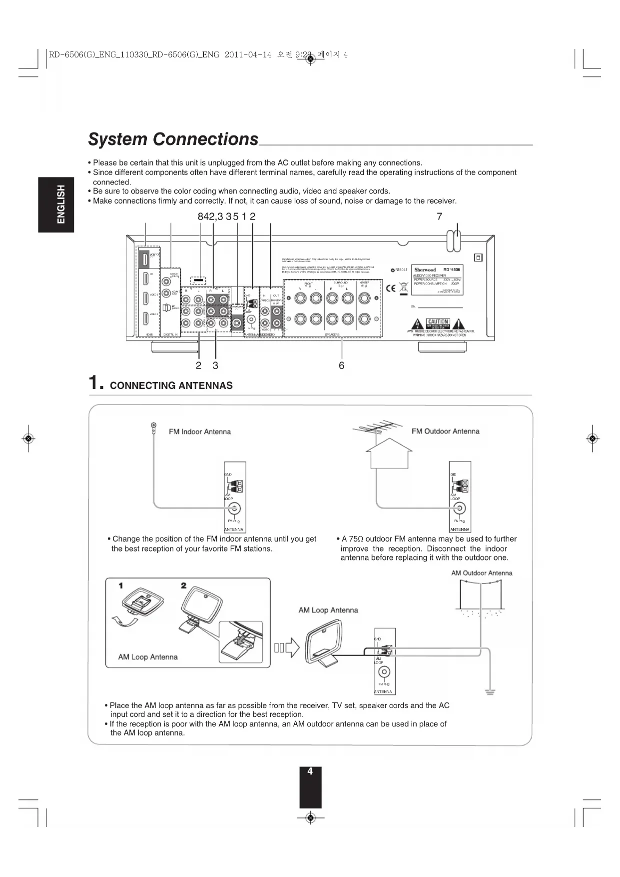
System Connections
- Please be certain that this unit is unplugged from the AC outlet before making any connections.
- Since different components often have different terminal names, carefully read the operating instructions of the component connected.
- Be sure to observe the color coding when connecting audio, video and speaker cords.
- Make connections firmly and correctly. If not, it can cause loss of sound, noise or damage to the receiver.
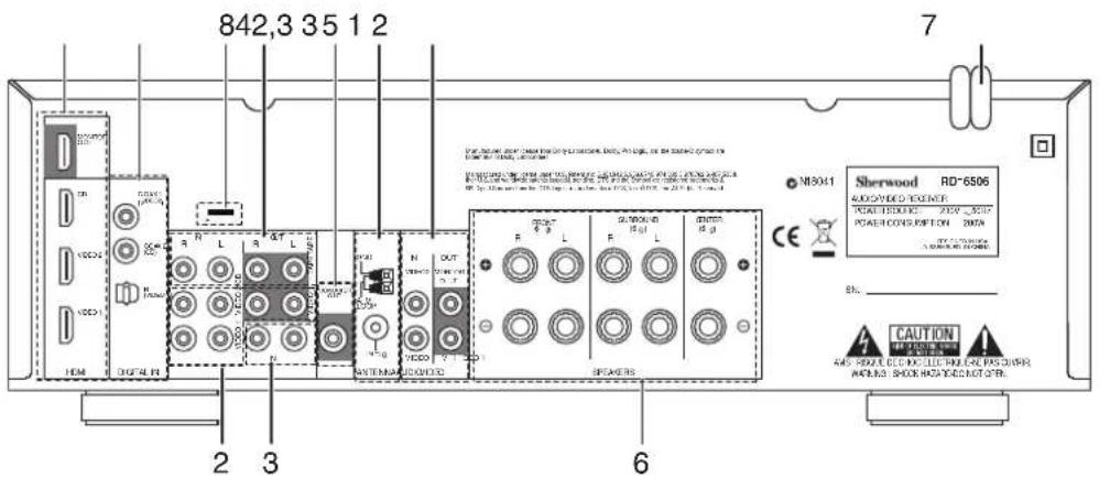
text_image
842,3 35 1 2 7 SHERWOOD RD-6506 RICHMOND POWER POWER CONTROL POWER CONTROL SHERWOOD N13041 CE BY: 1921-2019 SL. CAUTION ANS. SHOCKS FOR CHINA'S PAGAR INCOMES SHOCKS FOR CHINA'S PAGAR HOM DIGY4.PA 2 3 61. CONNECTING ANTENNAS
text_image
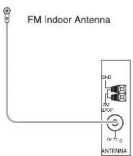
FM Indoor Antenna DAD AF DOP FN 72 ANTENNA- Change the position of the FM indoor antenna until you get the best reception of your favorite FM stations.
text_image
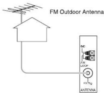
FM Outdoor Antenna A.M. A.M. LOCIP FAT10g ANTENNA- A 75Ω outdoor FM antenna may be used to further improve the reception. Disconnect the indoor antenna before replacing it with the outdoor one.
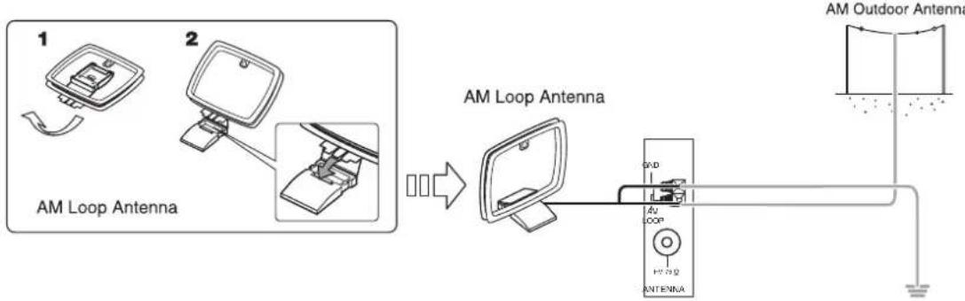
flowchart
graph LR
    A["1 AM Loop Antenna"] --> B["2 AM Loop Antenna"]
    B --> C["AM Outdoor Antenna"]
    C --> D["Ground"]
- Place the AM loop antenna as far as possible from the receiver, TV set, speaker cords and the AC input cord and set it to a direction for the best reception.
- If the reception is poor with the AM loop antenna, an AM outdoor antenna can be used in place of the AM loop antenna.
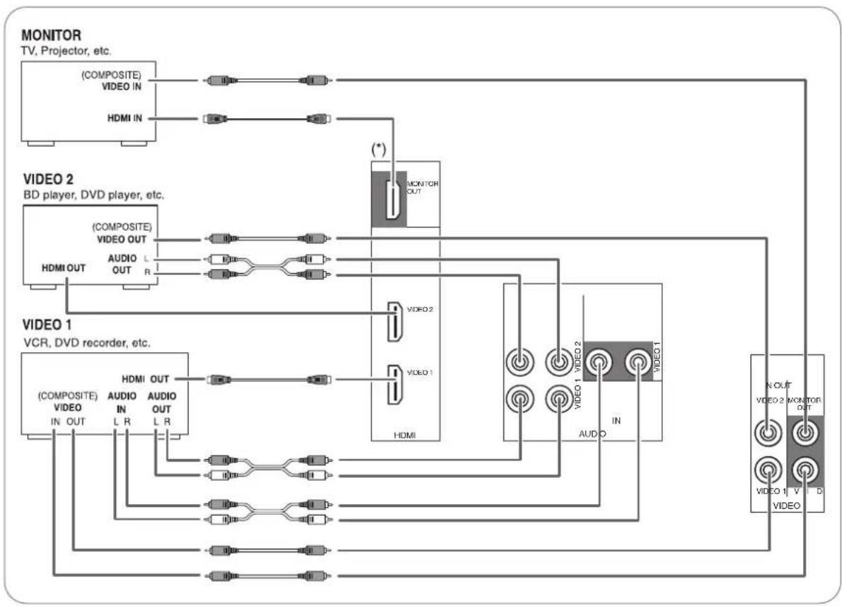
2. CONNECTING VIDEO COMPONENTS
- The jacks of VIDEO 1 may also be connected to a DVD recorder or other digital video recording component. For details, refer to the operating instructions of the component to be connected.
• The jacks of VIDEO 2 can also be connected to an additional video component such as a cable TV tuner or satellite system. - There are (composite) VIDEO jacks for analog video connections and the HDMI connectors for digital video and audio connections.
- For your reference, the excellence in picture quality is as follows: "HDMI" > "(composite) VIDEO".
Notes :
- When recording video program sources through the (composite) VIDEO 1 OUT jack or viewing video program sources through the (composite) MONITOR OUT jack, you must connect the (composite) VIDEO IN jack to the video playback components such as BD player, DVD player, etc.
flowchart
graph TD
    subgraph MONITOR
        A["MONITOR TV, Projector, etc."]
        B["(COMPOSITE) VIDEO IN"]
        C["HDMI IN"]
    end

    subgraph VIDEO 2
        D["VIDEO 2 BD player, DVD player, etc."]
        E["(COMPOSITE) VIDEO OUT"]
        F["HDMI OUT"]
        G["AUDIO L OUT R"]
    end

    subgraph VIDEO 1
        H["(COMPOSITE) VIDEO IN OUT"]
        I["HDMI OUT"]
        J["AUDIO IN L R"]
        K["AUDIO OUT L R"]
    end

    subgraph VIDEO 1 VCR, DVD recorder, etc.
        L["(COMPOSITE) VIDEO IN"]
        M["HDMI OUT"]
        N["AUDIO IN L R"]
        O["AUDIO OUT L R"]
    end

    subgraph VIDEO 1 VCR, DVD recorder, etc.
        P["(COMPOSITE) VIDEO IN"]
        Q["HDMI OUT"]
        R["AUDIO IN L R"]
        S["AUDIO OUT L R"]
    end

    subgraph VIDEO 1 VCR, DVD recorder, etc.
        T["(COMPOSITE) VIDEO IN"]
        U["HDMI OUT"]
        V["AUDIO IN L R"]
        W["AUDIO OUT L R"]
    end

    subgraph VIDEO 1 VCR, DVD recorder, etc.
        X["(COMPOSITE) VIDEO IN"]
        Y["HDMI OUT"]
        Z["AUDIO IN L R"]
        AA["AUDIO OUT L R"]
    end

    subgraph VIDEO 1 VCR, DVD recorder, etc.
        AB["(COMPOSITE) VIDEO IN"]
        AC["HDMI OUT"]
        AD["AUDIO IN L R"]
        AE["AUDIO OUT L R"]
    end

    subgraph VIDEO 1 VCR, DVD recorder, etc.
        AF["(COMPOSITE) VIDEO IN"]
        AG["HDMI OUT"]
        AH["AUDIO IN L R"]
        AI["AUDIO OUT L R"]
    end

    subgraph VIDEO 1 VCR, DVD recorder, etc.
        AJ["(COMPOSITE) VIDEO IN"]
        AK["HDMI OUT"]
        AL["AUDIO IN L R"]
        AM["AUDIO OUT L R"]
    end

    subgraph VIDEO 1 VCR, DVD recorder, etc.
        AN["(COMPOSITE) VIDEO IN"]
        AO["HDMI OUT"]
        AP["AUDIO IN L R"]
        AQ["AUDIO OUT L R"]
    end

    subgraph VIDEO 1 VCR, DVD recorder, etc.
        AR["(COMPOSITE) VIDEO IN"]
        AS["HDMI OUT"]
        AT["AUDIO IN L R"]
        AU["AUDIO OUT L R"]
    end

    subgraph VIDEO 1 VCR, DVD recorder, etc.
        AU --> AV["HDMI OUT"]
        AW["AUDIO IN L R"]
        AX["AUDIO OUT L R"]
    end

    subgraph VIDEO 1 VCR, DVD recorder, etc.
        AX --> AXA["HDMI OUT"]
        AXB["AUDIO IN L R"]
        AXC["AUDIO OUT L R"]
    end

    subgraph VIDEO 1 VCR, DVD recorder, etc.
        AX --> AXB["HDMI OUT"]
        AXC["AUDIO IN L R"]
        AXD["AUDIO OUT L R"]
    end

    subgraph VIDEO 1 VCR, DVD recorder, etc.
        AX --> AXC["AUDIO IN L R"]
        AXD --> AXD["AUDIO OUT L R"]
    end
Continued
■HDMI (High Definition Multimedia Interface) connection : (\*)
- You can connect the source component (DVD player, etc.) to the display component (TV, projector, etc.) through this receiver with using a commercially available HDMI cord.
- The HDMI connection can carry uncompressed digital video signals and digital audio signals.
- The HDMI video stream signals (video signals) are theoretically compatible with DVI-D. When connecting to a TV monitor, etc., equipped with DVI-D connector, it is possible to connect using a commercially available HDMI-DVI converter cord. Since the HDMI-to-DVI connection cannot carry any audio signals, set the HDMI AUDIO OUT to AMP to hear the HDMI digital audio signals on this receiver.(For details, refer to "When selecting the HDMI AUDIO OUT" on page 42.)
■ Copyright protection system
- This unit supports HDCP (High-bandwidth Digital Contents Protection), technology to protect copyright of digital video signals against illegal duplication. HDCP must also be supported on the components connected to this unit.
- HDMI, the HDMI logo and High-Definition Multimedia Interface are trademarks or registered trademarks of HDMI licensing LLC.
Notes :
- For stable signal transfer, we recommend using HDMI cables that are a maximum of 5 meters in length.
- Among the components that support HDMI, some components can control other components via the HDMI connector. For details on the HDMI function, refer to “CONFIRMING THE HDMI FUNCTION” on page 28 and “SETTING THE HDMI” on page 42.
- The audio signals from the HDMI connector (including the sampling frequency and bit length) may be limited by the component that is connected.
- The video signals will not be output properly if a component incompatible with HDCP is connected.
- If the resolutions of the video signals which are output from the MONITOR OUTs and your monitor TV are not matched, the picture is not clear, natural or displayed. In this case, change the setting of the resolution on the source component (BD player, etc.) to one which the monitor TV can handle. (For details, refer to the operating instructions of the source component.)
- When you want to enjoy only the picture on your TV, not the sound, you should set the HDMI AUDIO OUT to AMP not to output the digital audio signal from the HDMI MONITOR OUT of this receiver. (For details, refer to "When selecting the HDMI AUDIO OUT" on page 42.)
3. CONNECTING AUDIO COMPONENTS
- The TAPE IN/OUT jacks can be connected to audio recording equipment such as a tape deck, an MD recorder, etc.
- The HDMI IN of CD can be connected to an additional video component without analog video jacks.
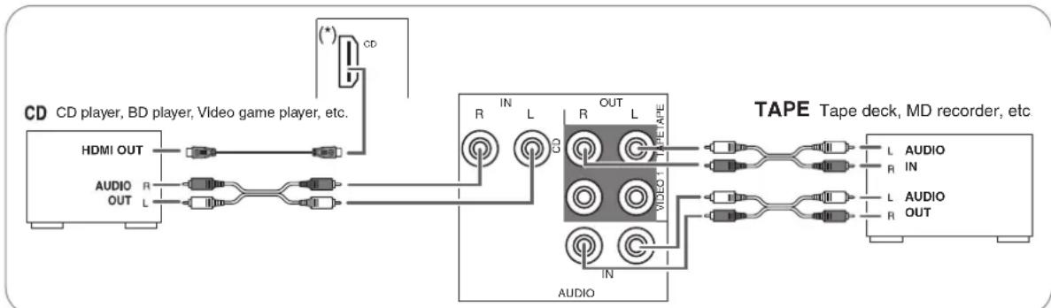
flowchart
graph LR
    A["CD CD player, BD player, Video game player, etc."] --> B["HDMI OUT"]
    A --> C["AUDIO R OUT L"]
    B --> D["CD"]
    C --> D
    D --> E["TAPE Tape deck, MD recorder, etc."]
    E --> F["L AUDIO IN"]
    E --> G["L AUDIO OUT"]
    H["(*)"] --> D
    I["IN"] --> D
    J["IN"] --> E
    K["IN"] --> E
4. CONNECTING DIGITAL INS
• The OPTICAL and the COAXIAL DIGITAL OUTs of the components that are connected to CD, VIDEO 1 and VIDEO 2 of this unit can be connected to these DIGITAL INs.
- A digital input should be connected to the components such as a CD player, DVD player, etc. capable of outputting DTS Digital Surround, Dolby Digital or PCM format digital signals, etc.
- For details, refer to the operating instructions of the component connected.
- When making the COAXIAL DIGITAL connection, be sure to use a 75Ω COAXIAL cord, not a conventional AUDIO cord.
- Some of the commercially available optical fiber cords cannot be used for the equipment. If there is an optical fiber cord which cannot be connected to your equipment, consult your dealer or nearest service organization.
Note :
- Be sure to make either a OPTICAL or a COAXIAL DIGITAL connection on each component. (You don't need to do both.)
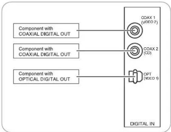
flowchart
graph TD
    A["Component with COAXIAL DIGITAL OUT"] --> B["COAX 1 (VIDEO 2)"]
    C["Component with COAXIAL DIGITAL OUT"] --> D["COAX 2 (CD)"]
    E["Component with OPTICAL DIGITAL OUT"] --> F["OPT (VIDEO 1)"]
    B --> G["DIGITAL IN"]
    D --> G
    F --> G
■Digital input default settings
- If you connect the DIGITAL INs to your components, it is easier to do so following the default settings.
- If your DIGITAL connections are different from default settings, you should assign the DIGITAL INs you used with the "When selecting the AUDIO ASSIGN" procedure on page 33.
- The default settings are as follows: OPTICAL IN : VIDEO 1, COAX 1 IN : VIDEO 2, COAX 2 IN : CD
5. CONNECTING SUBWOOFER PREOUT
- To emphasize the deep bass sounds, connect a powered subwoofer.
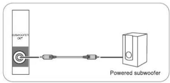
text_image
SUBWOOFER OUT Powered subwoofer6. CONNECTING SPEAKERS
- Be sure to connect speakers firmly and correctly according to the channel(left and right) and the polarity (+ and -). If the connections are faulty, no sound will be heard from the speakers, and if the polarity of the speaker connection is incorrect, the sound will be unnatural and lack bass.
- For installing the speakers, refer to "Speaker placement" on page 9.
• After installing the speakers, first adjust the speaker settings according to your environment and speaker layout.
(For details, refer to "SETTING THE SPEAKER SETUP" on page 34.)
Caution :
- Be sure to use the speakers with the impedance of 6 ohms or above.
- Do not let the bare speaker wires touch each other or any metal part of this unit. This could damage this unit and/or the speakers.
- Never touch the speaker terminals while the AC input cord is connected to the wall AC outlet. Doing so could result in electric shocks.
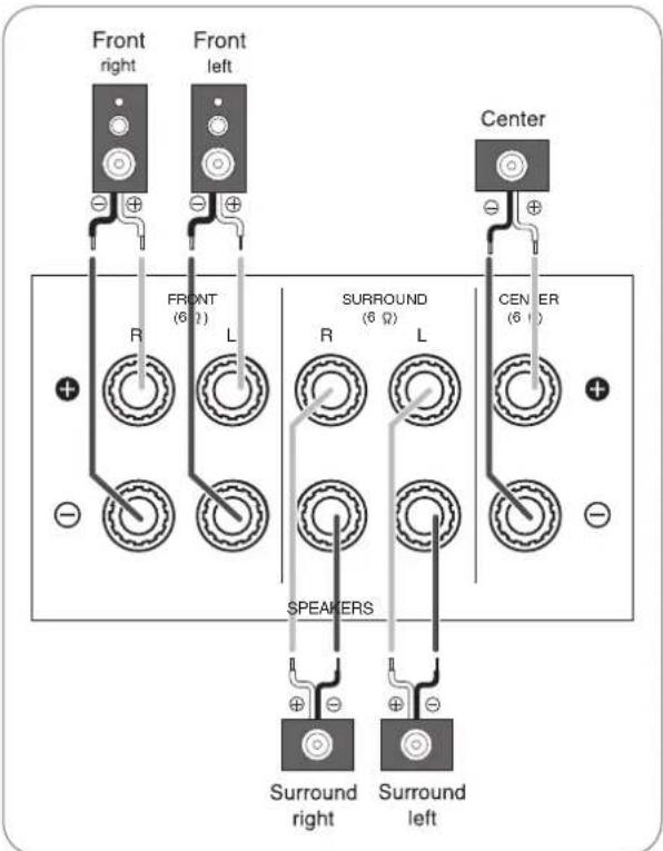
text_image
Front right Front left Center R FRONT (6 Ω) L SURROUND (6 Ω) R L CENTER (6 Ω) SPEAKERS Surround right Surround left■ Connecting speaker wire
1. Strip away approx. 10 mm (3/8 inch) of wire insulation, then twist the wire ends tight. | 2. Loosen by turning the speaker terminal counter-clockwise. | 3. Insert the bare part of the wire. | 4. Tighten by turning it clockwise. |
7. AC INPUT CORD
- Plug the cord into a wall AC outlet.
8. TERMINAL FOR UPGRADES
- This terminal may be used in the future to update the operating software so that it will be able to support new digital audio formats, etc.
Note :
- Programming for upgrades requires specialized programming knowledge and for that reason we recommend that it only be done by qualified installers.
Speaker placement
Ideal speaker placement varies depending on the size of your room and the wall coverings, etc. The typical example of speaker placement and recommendations are as follows:
■Front left and right speakers and center speaker
- Place the front speakers with their front surfaces as flush with TV or monitor screen as possible.
- Place the center speaker between the front left and right speakers and no further from the listening position than the front speakers.
- Place each speaker so that sound is aimed at the location of the listener's ears when at the main listening position.
■Surround left and right speakers
- Place the surround speakers approximately 1 meter (40 inches) above the ear level of a seated listener on the direct left and right of them or slightly behind.
Subwoofer
- The subwoofer reproduces powerful deep bass sounds. Place a subwoofer anywhere in the front as desired.
Notes :
- When using a conventional TV, to avoid interference with the TV picture, use only magnetically shielded front left and right and center speakers.
- To obtain the best surround effects, the speakers except the subwoofer should be full range speakers.
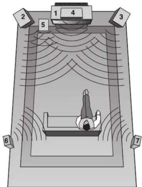
text_image
1 2 3 4 5 6 7- TV or Screen
- Front left speaker
- Front right speaker
- Center speaker
- Subwoofer
- Surround left speaker
- Surround right speaker
Front Panel Controls
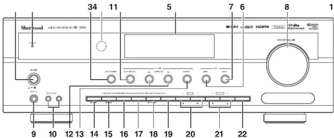
text_image
Sherwood AutoCAD 8000 配置开关 RD 6506 34 11 5 7 6 8 1 DAS HOTET HDMI TDAS Digital Tenset Display 2.0V DC/DC DC/DC DC/DC DC/DC DC/DC DC/DC DC/DC DC/DC DC/DC DC/DC DC/DC DC/DC DC/DC DC/DC DC/DC DC/DC DC/DC DC/DC DC/DC DC/DC DC/DC DC/DC DC/DC DC/DC DC/DC DC/AC DC/AC DC/AC DC/AC DC/AC DC/AC DC/AC DC/AC DC/AC DC/AC DC/AC DC/AC DC/AC DC/AC DC/AC DC/AC DC/AC DC/AC DC/AC DC/AC DC/AC DC/AC DC/AC DC/AC DC/AC DC/ATC DC/ATC DC/ATC DC/ATC DC/ATC DC/ATC DC/ATC DC/ATC DC/ATC DC/ATC DC/ATC DC/ATC DC/ATC DC/ATC DC/ATC DC/ATC DC/ATC DC/ATC DC/ATC DC/ATC DC/ATc DC/ATc DC/ATc DC/ATc DC/ATc DC/ATc DC/ATc DC/ATc DC/ATc DC/ATc DC/ATc DC/ATc DC/ATc DC/ATc DC/ATc DC/ATc DC/ATc DC/ATc DC/ATc DC/ATc DC/ATC- POWER switch
- STANDBY indicator
- POWER ON/STANDBY button
- REMOTE SENSOR
- FLUORESCENT DISPLAY For details, see below.
- VIDEO INPUT SELECTOR button
- AUDIO INPUT SELECTOR button
- MASTER VOLUME knob
- HEADPHONE jack
- AUX 1, 2 IN jacks For details, see next page.
-
AUTO/MANUAL button
-
SURROUND MODE SELECT (▶/◀) buttons
- STEREO button
- SPEAKER button
- AUDIO ASSIGN button
- TONE MODE button
- CHANNEL LEVEL button
- SETUP button
- ENTER/MEMORY button
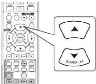
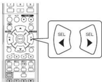
- TUNING UP/DOWN(+/-), CURSOR LEFT/RIGHT(◄/►) buttons
- PRESET UP/DOWN(+/-), CURSOR UP/DOWN(▲/▼) buttons
- BAND button
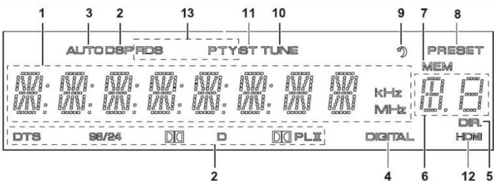
■FLUORESCENT DISPLAY
text_image
1 3 2 13 11 10 9 7 8 AUTO DSPRDS PTYST TUNE *) PRESET MEM kHz MHz DIR. HDMI DTS 86/24 D D DIO PLI DIGITAL 2 4 6 12 5- Input, frequency, volume level, operating information, etc.
- Surround mode indicators
- AUTO indicator
- DIGITAL INPUT indicator
- DIRECT indicator
- Preset number display
-
MEMORY indicator
-
PRESET indicator
- SLEEP indicator
- TUNED indicator
- STEREO indicator
- HDMI indicator
- RDS indicators
(Regional option for Europe, etc.)
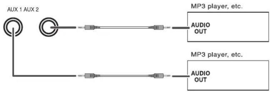
■AUX 1,2 IN JACKS
• The AUX 1, 2 IN jacks can be connected to additional audio components such as an MP3 player, etc.
Note :
- When connecting these jacks to an MP3 player, etc., you should use the stereo mini cord, not a mono mini cord.
text_image
AUX 1 AUX 2 MP3 player, etc. AUDIO OUT MP3 player, etc. AUDIO OUTRemote Controls
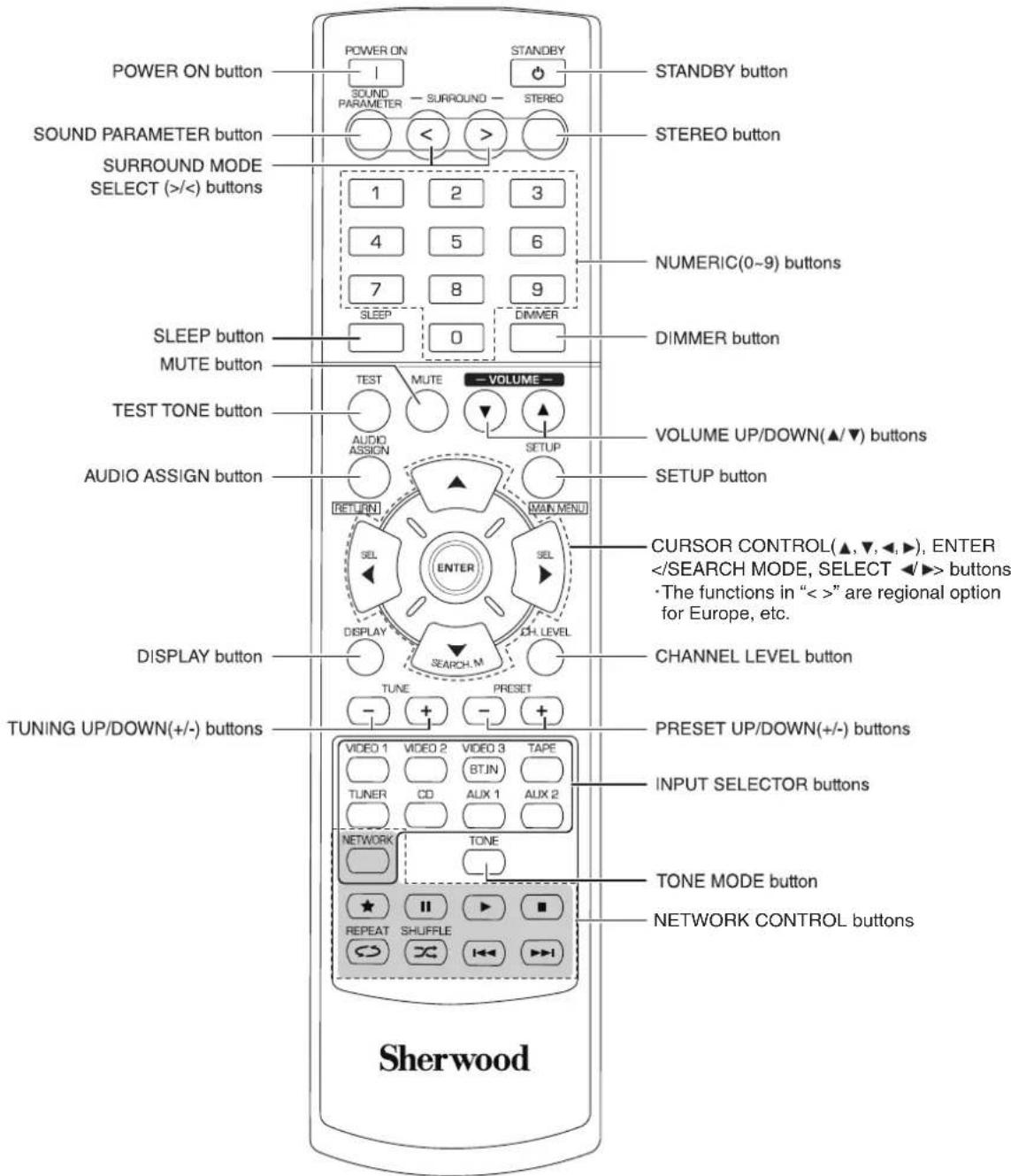
text_image
POWER ON button SOUND PARAMETER button SURROUND MODE SELECT (>) buttons SLEEP button MUTE button TEST TONE button AUDIO ASSIGN button DISPLAY button TUNING UP/DOWN(+/-) buttons POWER ON 1 SOUND PARAMETER SURROUND STEREO 1 2 3 4 5 6 7 8 9 SLEEP 0 DIMMER STANDBY button STEREO button NUMERIC(0~9) buttons DIMMER button VOLUME UP/DOWN(▲/▼) buttons SETUP button CURSOR CONTROL(▲,▼,◀,▶), ENTER <Note:
- The VIDEO 3 and NETWORK CONTROL buttons are not available for this receiver.
text_image
7m 30° 30° • Use the rest feet) and a- Use the remote control unit within a range of about 7 meters (23 feet) and angles of up to 30 degrees aiming at the remote sensor.
LOADING BATTERIES
- Remove the cover.
- Load two batteries ("AAA" size, 1.5 V) matching the polarity.
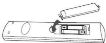
natural_image
Line drawing of a battery being inserted into a remote control unit (no text or symbols)- Remove the batteries when they are not used for a long time.
- Do not use the rechargeable batteries (Ni-Cd type).
Operations
■Note : Before operating this receiver, first set this unit as desired for optimum performance, doing the system setup procedures. (For details, refer to "System Setup" on page 29.)
LISTENING TO A PROGRAM SOURCE
Before operation
- Enter the standby mode.
- The STANDBY indicator lights up. This means that the receiver is not disconnected from the AC mains and a small amount of current is retained to support the operation readiness.
- To switch the power off, push the POWER switch again.
- Then the power is cut off and the STANDBY indicator goes off.
- The auto power save is a function that automatically turns the power off to enter the standby mode. When any button is not pressed for more than the time you set, it will function. (For details, refer to "When selecting the AUTO POWER SAVE" on page 31.)
■ Auto Power Save
1. In the standby mode, turn the power on.
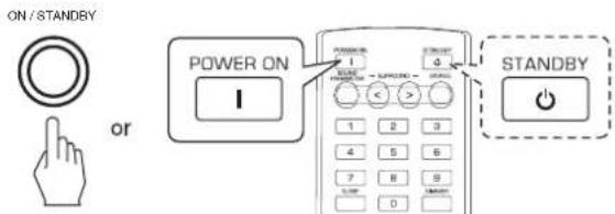
text_image
ON / STANDBY POWER ON I 1 2 3 4 5 6 7 8 9 0 D STANDBY- Each time the POWER ON/STANDBY button on the front panel is pressed, the receiver is turned on to enter the operating mode or off to enter the standby mode.
- On the remote control, press the POWER ON button to enter the operating mode or press the STANDBY button to enter the standby mode.
2. Switch the speakers on.
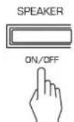
- Then "SP ON" is displayed and the sound can be heard from the speakers connected to the speaker terminals.
- When using the headphones for private listening, press the SPEAKER button again to switch the speakers off("SP OFF" is displayed).
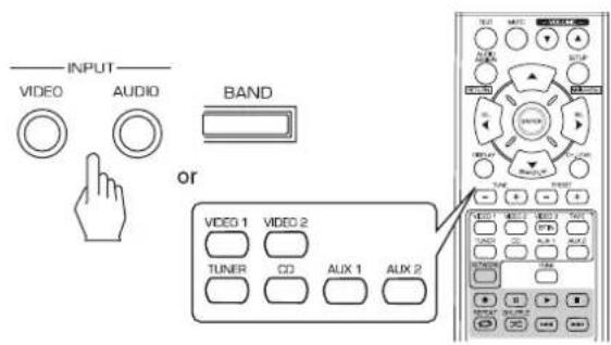
3. Select the desired input source.

text_image
INPUT VIDEO AUDIO BAND or VIDEO 1 VIDEO 2 TAPE TUNER CD AUX 1 AUX 2- Each time the "VIDEO" button on the front panel is pressed, the input source changes as follows:
VIDEO 1 → VIDEO 2 - Each time the "AUDIO" button on the front panel is pressed, the input source changes as follows:
CD → AUX 1 → TV* → AUX 2 → TAPE → TUNER
(Frequency display)
*: Only when the HDMI CONTROL is set to ON, you can hear the digital audio signals from TV via a HDMI cable. (For details, refer to "When selecting the HDMI CONTROL" on page 42.)
• Each time the BAND button(or the TUNER button on the remote control) is pressed, the band changes as follows:
→ FM ST → FM MONO → AM
When CD, VIDEO 1 \~ 2 is selected as an input source
4. Select the digital or the analog input connected as desired.
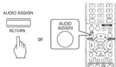
text_image
AUDIO ASSIGN RETURN or AUDIO ASSIGN• Each time this button is pressed, the corresponding input is selected as follows:
O(ptical) → C(oaxial) 1 → C(oaxial) 2 → A(nalog)
Notes :
- When the HDMI IN connector is connected to your video component, you cannot assign the audio input as desired. (It means that only the HDMI digital audio signals can be heard.)
- When the HDMI IN connector is not connected (and the "HDMI" indicator flickers), you can assign the audio input.
- When AUX 1, AUX 2, TAPE or tuner is selected as an input source, the digital input cannot be selected.
- When the selected digital input is not connected, the "DIGITAL" indicator flickers and the analog input is automatically selected.
- The selected digital input or analog input is automatically assigned to the corresponding input source on the INPUT setup menu. (For details, refer to "SETTING THE INPUT" on page 33.)
- The sound from the component connected to the selected digital input can be heard regardless of the selected input source.
5. Operate the selected component for playback.
- When playing back the program sources with surround sound, refer to "ENJOYING SURROUND SOUND" on page 17.
6. Adjust the (overall) volume.
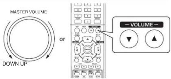
text_image
MASTER VOLUME DOWN UP or — VOLUME —7. To mute the sound.
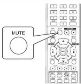
text_image
MUTE- "MUTING" is displayed.
• To resume the previous sound level, press it again.
8. To listen with the headphones.

natural_image
Line drawing of a pair of headphones connected to a circular earbell (no text or symbols)- Be sure to switch the speakers off.
- When listening to a DTS or Dolby Digital program source, if the headphones are plugged in and the SPEAKER button is set to off, it enters the 2CH downmix mode automatically. (For details, refer to "2CH downmix mode" on page 17.)
Note:
- Be careful not to set the volume too high when using headphones.
Adjusting the tone (bass and treble)
9. Enter the tone mode.
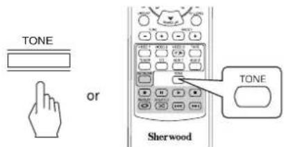
text_image
TONE or TONE Sherwood• The tone mode is displayed for several seconds.
TONE: OFF
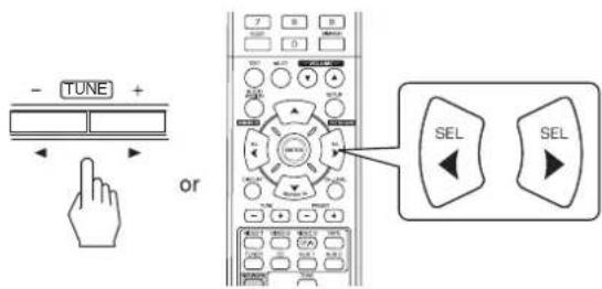
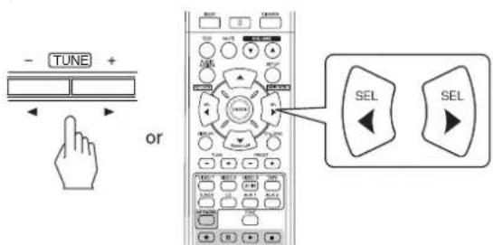
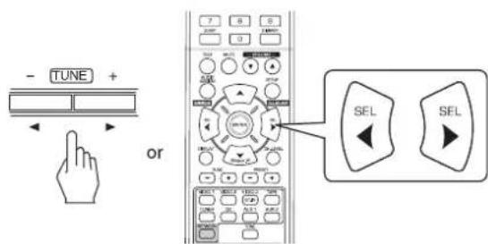
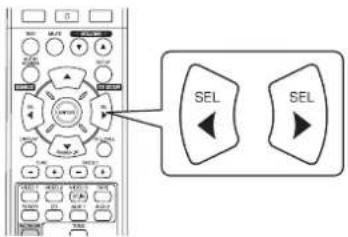
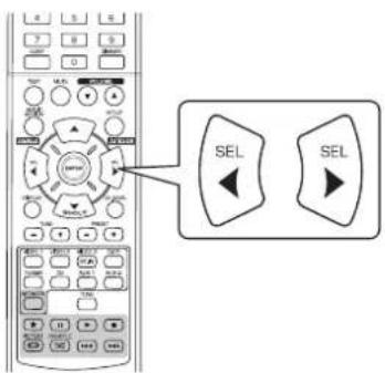
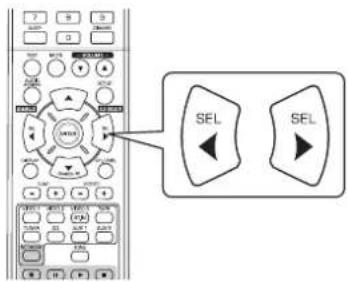
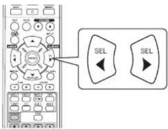
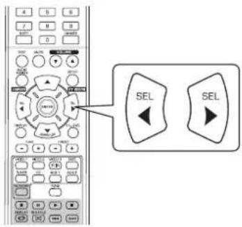
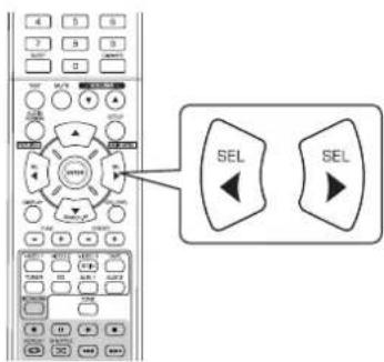
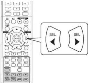
10. Press the CURSOR LEFT(◀)/RIGHT(▶) buttons to select the desired tone mode.
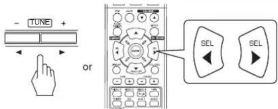
text_image
- TUNE + or SEL SEL• Each time these buttons are pressed, the tone mode is selected as follows :
OFF: To listen to a program source without the
↑ tone effect.("DIR" lights up.)
ON: To adjust the tone for your taste. ("DIR" goes off.)
■When the TONE is set to ON to adjust the tone (bass and treble).
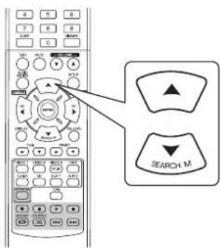
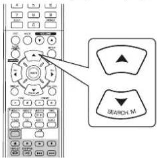
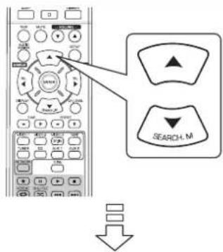
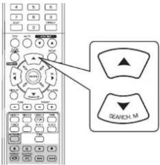
11. Press the CURSOR UP(▲)/DOWN(▼) buttons to select the desired tone.
text_image
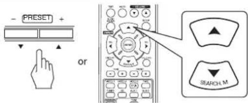
- PRESET + or SEARCH M• Each time these buttons are pressed, the tone is selected as follows:
→ BASS ↔ TRE (treble) ↔ TONE: ON ←
12. Press the CURSOR LEFT(◀)/RIGHT(▶) buttons to adjust the selected tone as desired.
- The tone level can be adjusted within the range of -10 \~ +10 dB.
- In general, we recommend the bass and treble to be adjusted to 0 dB (flat level).
- Extreme settings at high volume may damage your speakers.
- If the tone display disappears, start from the step 9 again.
SURROUND SOUND
- This receiver incorporates a sophisticated Digital Signal Processor that allows you to create optimum sound quality and sound atmosphere in your personal Home Theater.
Surround modes
■DTS Digital Surround
DTS Digital Surround(also called simply DTS) supports up to 5.1 discrete channels and uses less compression for high fidelity reproduction. Use it with DVDs and CDs bearing the DTS logo.
DTS 96/24
This is high resolution DTS with a 96 kHz sampling rate and 24 bit resolution, providing superior fidelity. Use it with DVDs bearing the DTS 96/24 logo.
Manufactured under license under U.S. Patent Nos: 5,956,674; 5,974,380; 6,487,535 & other U.S. and worldwide patents issued & pending. DTS, the Symbol, & DTS and the Symbol together are registered trademarks & DTS Digital Surround and the DTS logos are trademarks of DTS, Inc. Product includes software. © DTS, Inc. All Rights Reserved.
■Dolby Digital
Dolby Digital is the multi-channel digital signal format developed by Dolby Laboratories. Discs bearing the Dolby Digital logo includes the recording of up to 5.1 channels of digital signals, which can reproduce much better sound quality, spatial expansion and dynamic range characteristics than the previous Dolby Surround effect.
■Dolby Pro Logic II surround
This mode applies conventional 2-channel signals such as digital PCM or analog stereo signals as well as Dolby Surround signals, etc. to surround processing to offer improvements over conventional Dolby Pro Logic circuits. Dolby Pro Logic II surround includes 2 modes as follows:
• Dolby Pro Logic II Movie
When enjoying movies, this mode allows you to further enhance the cinematic quality by adding processing that emphasizes the sounds of the action special effects.
• Dolby Pro Logic II Music
When listening to music, this mode allows you to further enhance the sound quality by adding processing that emphasizes the musical effects.
■Dolby Pro Logic
This mode expands any 2-channel source(including Dolby Surround source) for 4 channel(front left, center, front right and surround) playback.
The surround channel is monaural, but is played through two surround speakers.
Manufactured under license from Dolby Laboratories. Dolby, Pro Logic, and the double-D symbol are registered trademarks of Dolby Laboratories.
- The following modes apply conventional 2-channel signals such as digital PCM or analog stereo signals to high performance Digital Signal Processor to recreate sound fields artificially. Select one of the 6 provided surround modes according to the program source you want to play.
Theater
This mode provides the effect of being in a theater when watching a play.
Movie
This mode provides the effect of being in a movie theater when watching a movie.
Hall
This mode provides the ambience of a concert hall for classical music sources such as orchestral, chamber music or an instrumental solo.
Game
This mode is suitable for video games.
Stadium
This mode provides the expansive sound field to achieve the true stadium effect when watching baseball or soccer games.
■Multi CH Stereo
This mode is designed for playing background music. The front and surround channels create a stereo image that encompasses the entire area.
Note: Before surround playback, first perform the speaker setup procedure, etc. on the SETUP menu for optimum performance. (For details, refer to "SETTING THE SPEAKER SETUP" on page 34.)
Depending on how to select a surround mode, select the auto surround mode or the manual surround mode.
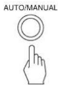
- Each time this button is pressed, the mode changes as follows: Auto surround mode: The optimum surround mode will be ("AUTO" indicator automatically selected depending on the signal lights up.) format being input.
Manual surround mode : You can select the desired of different ("AUTO" indicator goes off.) surround modes selectable for the signal being input with using the SURROUND MODE SELECT (>) buttons.
Notes :
- When the SPEAKER button is set to off or "C(Center)" and "S(Surround)" are set to "NO", the auto surround mode is invalid.
- Even when the auto surround mode is selected and the same type of digital signal format is being input, the optimum surround mode may vary depending on whether the speaker type is set to "NO" or not.
- When the auto surround mode is selected, the surround modes other than the optimum surround mode cannot be selected.
■When selecting the manual surround mode with pressing the AUTO/MANUAL button on the front panel Select the desired surround mode.
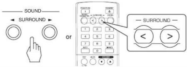
• Each time the SURROUND MODE SELECT (>/<) buttons are pressed, the surround mode changes depending on the input signal format as follows :
| Signal format being input | Selectable surround mode |
| Dolby Digital EX 6.1 channel sources, Dolby Digital 5.1 channel sources | DOLBY DIGITAL or <2 CH IN> * ^1 |
| Dolby Digital 2 channel sources, PCM (2 channel) sources, Analog stereo sources | DOLBY PLII MOVIE, DOLBY PLII MUSIC, THEATER, MOVIE, HALL, GAME, STADIUM, M.CH STEREO, DOLBY PRO LOGIC or <2 CH IN> * ^1 |
| DTS sources, DTS 96/24 sources | Corresponding DTS mode or <2 CH IN> * ^1 |
^1 : When "C(Center)" and "S(Surround)" are set to "NO", any surround mode cannot be selected and the source can be reproduced either in the stereo mode or in the 2CH downmix mode.
■To cancel the surround mode for stereo operation
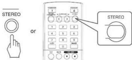
text_image
STEREO or STEREO- Depending on the signal format which is being input, either the stereo mode or the 2CH downmix mode is selected.
- To cancel either the stereo mode or the 2CH downmix mode, select the surround mode with using the SURROUND MODE SELECT (>/<) buttons.
■2CH downmix mode
- This mode allows the multi-channel signals encoded in DTS or Dolby Digital format to be mixed down into 2 front channels and to be reproduced through only two front speakers or through headphones.
- When the SPEAKER button is set to off to listen with headphones while playing the multi-channel digital signals from DTS or Dolby Digital sources, it will enter the 2CH downmix mode automatically.
When adjusting the sound parameters
- While playing digital signals form Dolby Digital program source or listening in Dolby Pro Logic II Music mode, you can adjust their parameters for optimum surround effects.
- Press the SOUND PARAMETER button.
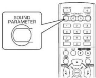
text_image
SOUND PARAMETER- Then "DRC: \~" (or "PANO : \~") is displayed for several seconds.
-
If the parameter mode disappears, press this button again.
-
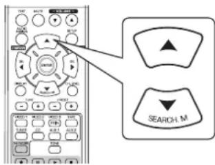
Press the CURSOR UP(▲)/DOWN(▼) buttons to select the desired parameter.
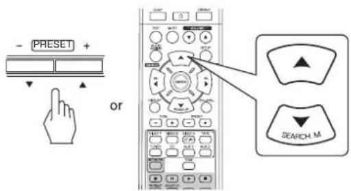
text_image
- PRESET + or SEARCH_M• Each time these buttons are pressed, the parameter mode changes as follows:
"DRC" ↔ "PANO" ↔ "C.WIDTH" ↔ "DIMEN" (Dynamic Range (Panorama) (Center width control) (Dimension control))
- "DRC" can be selected only while playing digital signals from Dolby Digital source.
-
"PANO", "C.WIDTH" and "DIMEN" can be selected only while listening in Dolby Pro Logic II Music mode.
-
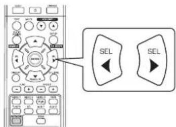
Press the CURSOR LEFT(◀)/RIGHT(▶) buttons to adjust the selected parameter as desired.
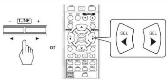
text_image
- TUNE + or SEL SEL■When selecting the "DRC (Dynamic Range Compression)"
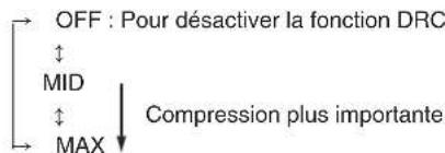
- This function compresses the dynamic range of previously specified parts of the Dolby Digital sound track (with extremely high volume) to minimize the difference in volume between the specified and non-specified parts. This makes it easy to hear all of the sound track when watching movies at night at low levels.
■Note : In some Dolby Digital softwares, DRC setting may not be valid.
OFF: To turn off the DRC function. (Default value) ↓ MID ↓ MAX ↓ Higher compression
■When selecting the "PANO (Panorama)"
This mode extends the front stereo image to include the surround speakers for an exciting "wraparound" effect with side wall imaging. Select "OFF" or "ON"(default value: OFF).
■When selecting the "C. WIDTH (Center width)" control
This adjusts the center image so it may be heard only from the center speaker, only from the left/right speakers as a phantom image, or from all three front speakers to varying degrees. The control can be set in 8 steps from 0 to 7(default value: 3).
■When selecting the "DIMEN (Dimension)" control This gradually adjusts the soundfield either towards the front or towards the rear. The control can be set in 7 steps from -3 to +3 (default value : 0).
- Repeat the above steps 2 and 3 to adjust other parameters.
Adjusting each channel level with test tone
- The volume level of each channel can be adjusted easily with the test tone function.
■Note : When the SPEAKER button is set to off, the test tone function does not work.
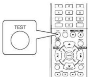
1. Enter the test tone mode.
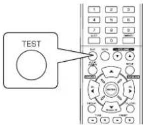
text_image
TEST- The test tone mode is displayed and will be heard from the speaker of each channel for 2 seconds as follows:
| FL | C | FR | SR | SL | SW |
| FrontLeft | Center | FrontRight | SurroundRight | SurroundLeft | Subwoofer |
- When the speaker setting is "NO", the test tone of the corresponding channel is not available.
- At each channel, adjust the level as desired until the sound level of each speaker is heard to be equally loud.
text_image
- TUNE + or SEL SEL- You can select the desired channel with pressing the CURSOR UP(▲)/DOWN(▼) buttons.
- Cancel the test tone function.
text_image
TESTAdjusting the current channel level
• After adjusting each channel level with test tone, adjust the channel levels either according to the program sources or to suit your tastes.
- You can adjust the current channel levels as desired. These adjusted levels are just memorized into user's memory ("CAL"), not into preset memory("REF 1", "REF 2").
1. Press the CHANNEL LEVEL button.
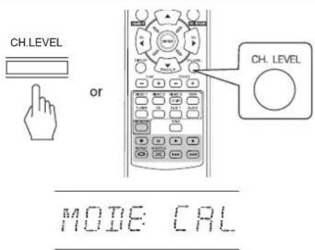
text_image
CH.LEVEL or CH. LEVEL MODE: CAL- Then the memory mode ("CAL", etc.) is displayed for several seconds.
- When the memory mode or channel level disappears, press this button again.
2. Select the desired channel.

text_image
- PRESET + or SEARCH_M• Each time these buttons are pressed, the corresponding channel is selected as follows:
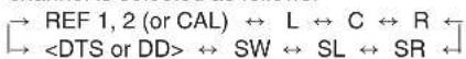
<>: Possible only when the digital signals from Dolby Digital or DTS program sources that includes LFE signal are input.
- Depending on the speaker settings ("NO") and surround mode, etc., some channels cannot be selected.
- When the SPEAKER button is set to off, only the Front Left, Front Right (and LFE) channels can be selected.
3. Adjust the level of the selected channel as desired.
text_image
- TUNE + or SEL SEL- The LFE level can be adjusted within the range of -10 \~ 0 dB and other channel levels within the range of -15 \~ +15 dB.
- In general, we recommend the LFE level to be adjusted to 0 dB.(However, the recommended LFE level for some early DTS software is -10 dB.) If the recommended levels seem too high, lower the setting as necessary.
4. Repeat the above steps 2 and 3 to adjust each channel level.
Memorizing the adjusted channel levels
- You can memorize the adjusted channel levels into preset memory("REF 1", "REF 2") and recall the memorized whenever you want.
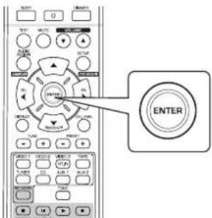
- After performing the steps 1 \~ 4 in "Adjusting the current channel level" procedure on page 20, press the ENTER(/MEMORY) button.
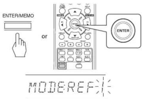
text_image
ENTER/MEMO or ENTER MODE:REF:- Then "1" of "REF 1" indication flickers for several seconds.
- Select the desired one of REF 1 and REF 2.

text_image
- TUNE + or SEL SEL- If the preset memory disappears, perform the above step 1 again.
- Confirm your selection.
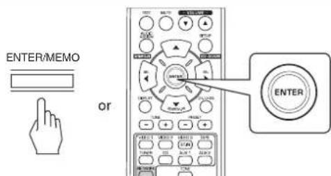
text_image
ENTER/MEMO OR ENTER- The adjusted channel levels have now been memorized into the selected memory.
Recalling the memorized channel levels
- Press the CHANNEL LEVEL button.
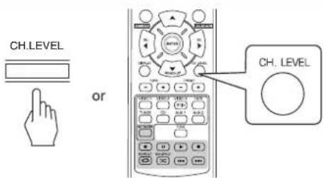
text_image
CH.LEVEL or CH. LEVEL- "CAL" (or "REF 1", etc.) is displayed for several seconds. - If the channel level mode display disappears, press this button again.
- Select the desired one of REF 1 and REF 2.
text_image
- TUNE + or SEL SEL- Then the channel levels memorized into the selected preset memory are recalled.
LISTENING TO RADIO BROADCASTS
Auto tuning
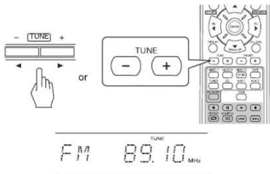
1. Select the desired band.
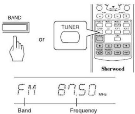
text_image
BAND or TUNER Sherwood F M 87.50 MHz Band Frequency• Each time this button is pressed, the band changes as follows;
- When FM stereo broadcasts are poor because of weak broadcast signals, select the FM mono mode to reduce the noise, then FM broadcasts are reproduced in monaural sound.
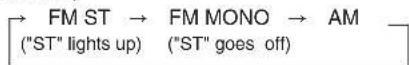
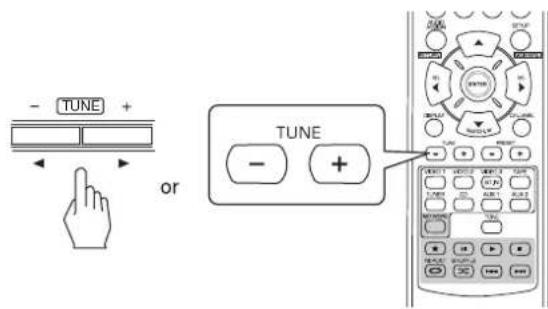
2. Press the TUNING UP(+)/DOWN(-) buttons for more than 0.5 second.
text_image
- TUNE + or TUNE - + FM 89.10 MHz TUNE- The tuner will now search until a station of sufficient strength has been found. The display shows the tuned frequency and "TUNE".
- If the station found is not the desired one, simply repeat this operation.
- Weak stations are skipped during auto tuning.
Manual tuning
- Manual tuning is useful when you already know the frequency of the desired station. - After selecting the desired band, press the TUNING UP(+) / DOWN(-) buttons repeatedly until the right frequency has been reached.
text_image
- TUNE + or TUNE - +Auto presetting
- Auto presetting function automatically searches for FM stations only and store them in the memory.
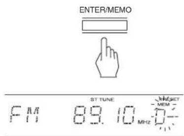
- While listening to FM radio broadcasts, press and hold down the ENTER(/MEMORY) button for more than 2 seconds.
text_image
ENTER/MEMO or ENTER- Then "AUTO MEM" flickers and this receiver starts auto presetting.
• To stop auto presetting, press this button again. - Up to 30 FM stations can be stored.
Notes:
• FM stations of weak strength cannot be memorized.
- To memorize AM stations or weak stations, preform "Manual presetting" procedure with using "Manual tuning" operation.
Manual presetting
- You can store up to 30 preferred stations in the memory.
-
Tune in the desired station with auto or manual tuning.
-
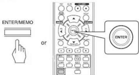
Press the ENTER(/MEMORY) button.
text_image
ENTER/MEMO ST TUNE MHz F M 89.10- "MEM", etc. flicker.
- Select the desired preset number (1\~30) and press the ENTER(/MEMORY) button.
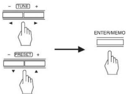
flowchart
graph TD
    A["Input: -TUNE +"] --> B["Insert: TUNE +"]
    C["Input: -PRESET +"] --> D["Insert: PRESET +"]
    E["Input: ENTER/MEMO"] --> F["Insert: ENTER/MEMO"]
- When using the NUMERIC buttons on the remote control.
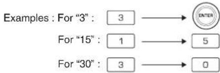
flowchart
graph LR
    A["Examples : For "3": 3"] --> B["ENTER"]
    C["For "15": 1"] --> D["5"]
    E["For "30": 3"] --> F["0"]
• The station has now been stored in the memory.
- When specifying a two digit number with using the NUMERIC buttons, the station is stored automatically without pressing the ENTER(/MEMORY) button.
- A stored frequency is erased from the memory by storing another frequency in its place.
- Repeat the above steps1 to 3 to memorize other stations.
The following items, set before the receiver is turned off, are memorized.
• INPUT SELECTOR settings
- Surround mode settings
- Preset stations,etc.
Tuning to preset stations
• After selecting the tuner as an input source, select the desired preset number.
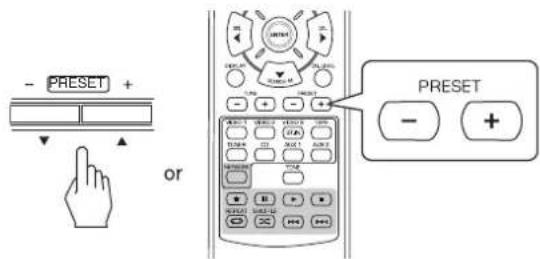
text_image
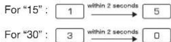
- PRESET + or PRESET - +- When using the NUMERIC buttons on the remote control.
Examples: For "3": 3
RDS Tuner (Regional Option for some countries in Europe, etc.)
LISTENING TO RDS BROADCASTS(FM ONLY)
RDS(Radio Data System) is a method for sending information signals together with the transmitter signals. Your tuner is capable of translating these signals and putting the information on the display. These codes contain the following information. Program Service name (PS), A list of Program Types (PTY), Radio Text (RT).
Notes :
• In the other countries, RDS tuner function cannot be available.
• RDS is only possible in the FM band.
- RDS searches for the preset stations only. If no stations have been stored in the memory, or if the program type could not be found among the preset stations, "NO PTY" is displayed.
Therefore, preset the radio stations before searching for RDS stations.
Searching for stations by program type
- You can search for stations by program type.
- In the FM mode, press the SEARCH MODE button.
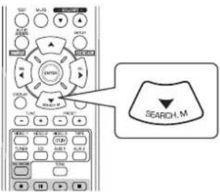
text_image
TAF M-FL WALP SHEEP ENGLISH SHEEP SHEEP LIME INLET SELECT SELECT OR SELECT OR SELECT OR SELECT OR SELECT OR SELECT OR SELECT OR SELECT OR SELECT OR SELECT OR SELECT OR SELECT OR SELECT OR SELECT OR SELECT OR SELECT OR SELECT OR SELECT OR SELECT OR SELECT OR SELECT OR SELECT OR SELECT OR SELECT OR SELECT OR SELECT OR SELECT OR SELECT OR SELECT OR SELECT OR SELECT OR SELECT OR SELECT OR SELECT OR- "SEARCH" is displayed for several seconds.
- While displaying "SEARCH", select the desired program type.
text_image
SEL SELNEWS
• Each time these buttons are pressed, one of different types of programs is selected.
(NEWS, AFFAIRS, INFO, SPORT, EDUCATE, DRAMA, CULTURE, SCIENCE, VARIED, POP M, ROCK M, EASY M, LIGHT M, CLASSICS, OTHER M, WEATHER, FINANCE, CHILDREN, SOCIAL, RELIGION, PHONE IN, TRAVEL, LEISURE, JAZZ, COUNTRY, NATION M, OLDIES, FOLK M, DOCUMENT)
- If "SEARCH" disappears, press the SEARCH MODE button again.
- While displaying the selected program type, press the ENTER button.
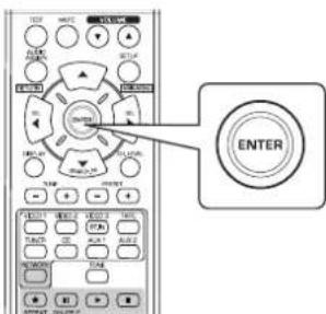
text_image
ENTER- The tuner starts searching through the preset station for a match.
- When a station is found, the search stops and the station plays.
- If no station is found, "NO PTY" is displayed.
Displaying RDS information
In the FM mode,
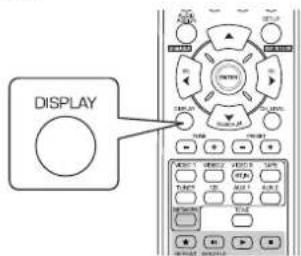
text_image
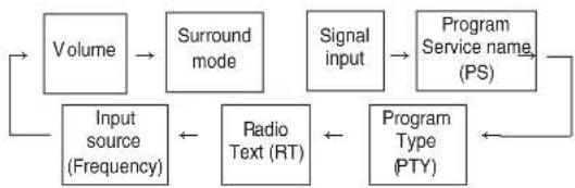
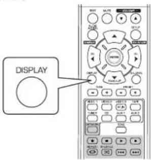
DISPLAY• Each time this button is pressed, the display mode changes as follows:
flowchart
graph LR
    A["Input source (Frequency)"] --> B["Volume"]
    B --> C["Surround mode"]
    C --> D["Signal input"]
    D --> E["Program Service name (PS)"]
    E --> F["Program Type (PTY)"]
    F --> G["Radio Text (RT)"]
    G --> A
* Program Service Name(PS)-The name of the radio station.
* Program Type(PTY)-This indicates the kind of program currently being broadcast.
* Radio Text(RT)-Messages sent by the radio station. For example, a talk radio station may provide a phone number as RT.
- If the signals are too weak or no RDS service is available, "NO NAME", "NO PTY" or "NO TEXT" will be displayed.
RECORDING
- The digital signals from the coaxial, optical digital input or HDMI IN can be heard but cannot be recorded.
- When recording the analog signals from CD, VIDEO 1\~2, be sure to select the analog input. (For details, refer to "When CD, VIDEO 1\~2 is selected as an input source" on page 14.)
- The volume and tone (bass, treble) settings have no effect on the recording signals.
Recording with TAPE
- Select the desired input as a recording source except for TAPE.
text_image
INPUT VIDEO AUDIO BAND or VIDEO 1 VIDEO 2 TUNER CD2 AUX 1 AUX 2- Start recording on the TAPE.
- Start play on the desired input.
Dubbing from video components onto VIDEO 1
- Select the VIDEO 2 as a recording source.
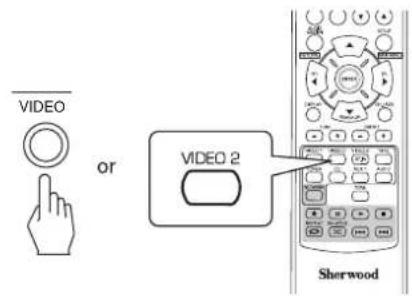
text_image
VIDEO or VIDEO 2 Sherwood- Start recording on the VIDEO 1.
- Start play on the desired input.
- The audio and video signals from the desired input will be dubbed onto the VIDEO 1 and you can enjoy them on the TV set and from the speakers.
OTHER FUNCTIONS
Operating the sleep timer
- The sleep timer allows the system to continue to operate for a specified period of time before automatically shutting off.
- To set the receiver to automatically turn off after the specified period of time.
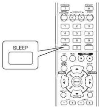
text_image
SLEEP• Each time this button is pressed, the sleep time changes as follows:
$$ \begin{array}{c}\rightarrow 1 0 \rightarrow 2 0 \rightarrow 3 0 \rightarrow \dots \rightarrow 9 0 \rightarrow O F F\\text { Unit:minutes }\end{array} $$
- While operating the sleep timer, " lights up.
- When the sleep time is selected, the fluorescent display is dimly lit.
Adjusting the brightness of the fluorescent display
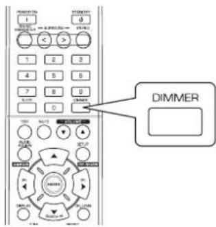
text_image
DIMMER 1 2 3 4 5 6 7 8 9 0 DIMMER• Each time this button is pressed, the brightness of the fluorescent display changes as follows:
$$ \rightarrow \text { ON } \rightarrow \text { dimmer } \rightarrow \text { OFF } $$
- In the display OFF mode, pressing some buttons cancel the display OFF mode to display the operation status.
Displaying the operation status
During playback,
text_image
DISPLAY• Each time this button is pressed, the display mode changes as follows:
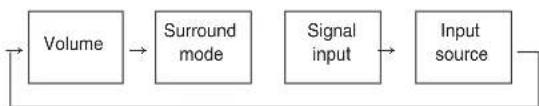
flowchart
graph LR
    A["Volume"] --> B["Surround mode"]
    B --> C["Signal input"]
    C --> D["Input source"]
    D --> A
- When the RDS tuner function is available in your country, for details on the FM mode information, see "Displaying RDS information" on page 25.
CONFIRMING THE HDMI FUNCTION
To use the HDMI control functions properly, it is recommend to confirm the HDMI control functions usable with each connected component by performing the following operations.
Note :
- Some HDMI control functions may not work with certain components and TV that are not compatible with them.
Before operation
- Check that this receiver, TV and player, etc are connected by HDMI cables.
- Check that the HDMI control of TV and the HDMI-connectable player are enabled.
(For details on the setups of TV and player, refer to their operating instructions.) - Set the HDMI CONTROL and the POWER CONTROL to ON to enable the HDMI control of this receiver. (For details, refer to "SETTING THE HDMI" on page 42.)
Confirming the basic HDMI operations
- Turn the power on for all the components connected by HDMI cables.
- Switch the TV input to the HDMI input connected to this receiver.
- Switch this unit input to the HDMI input source.
- Confirm that its picture is displayed and the sound is heard from the speakers properly.
Confirming the HDMI control functions
- Turn the power on for all the components connected by HDMI cables.
-
Turn the TV off to enter the standby mode.
-
Confirm that all the components are turned off.
- With all the components off, start playback on a player (connected by HDMI cable).
- Confirm that all the components are turned on and the inputs of this unit and TV are switched automatically.
System Setup
- The setup menu is displayed on the fluorescent display and allows you to perform the setup procedures easily. In most situations, you will only need to set this once during the installation and layout of your home theater, and it rarely needs to be changed later. The setup menu consists of 6 main menus; system, input, speaker setup, CH level, parameter and HDMI. These menus are then divided up into various sub-menus.
■ Navigating through the setup menu
- The explanations here assume you are using the buttons on the remote control when performing the setup menu operation. However, you can use the buttons on the front panel as well. The buttons on the front panel correspond to those on the remote control as shown below.
| Button on the remote control |  |  | 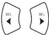 |   |
| Button on the front panel | SETUP[IMAGE]MAIN MENU | ENTER / MEMO[IMAGE] | - TUNE +[IMAGE]▲ | - PRESET +[IMAGE]▼▲ |
- Turn the setup menu on.
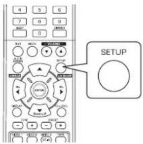
text_image
4 5 6 7 8 9 MINT 0 MOUT 1 2 3 4 5 6 SETUP SETUP
• The setup menu will be shown.
• To turn the menu off, press this button again.
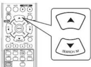
- Select the desired menu using the CURSOR UP(▲)/DOWN(▼) buttons.
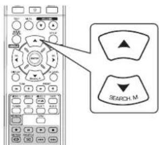
text_image
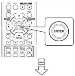
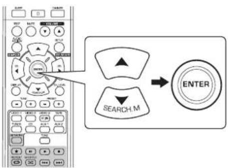
SEARCH.M- Confirm your selection.
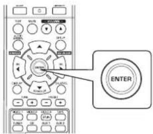
text_image
ENTER- When selecting "SYSTEM", see "SETTING THE SYSTEM" on page 31.
- When selecting "INPUT", see "SETTING THE INPUT" on page 33.
- When selecting "SPK SET", see "SETTING THE SPEAKER SETUP" on page 34.
- When selecting "CH LEVEL", see "SETTING THE CH LEVEL" on page 38.
- When selecting "PARAMTR", see "SETTING THE PARAMETER" on page 40.
- When selecting "HDMI", see "SETTING THE HDMI" on page 42.
- When selecting "EXIT", the setup menu will be turned off.
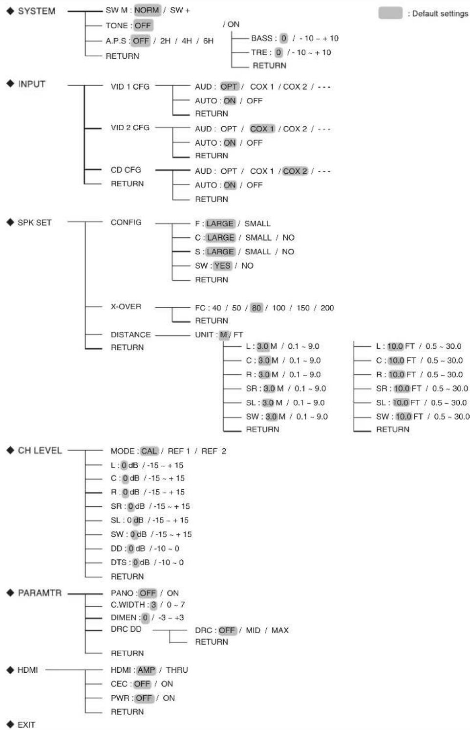
■ Setup menu flow
- The setup menu flow is as follows :
flowchart
graph TD
    A["SYSTEM"] --> B["SW M : NORM / SW +"]
    B --> C["TONE : OFF"]
    C --> D["A.P.S : OFF / 2H / 4H / 6H"]
    D --> E["RETURN"]
    F["INPUT"] --> G["VID 1 CFG"]
    G --> H["AUD : OPT / COX 1 / COX 2 / ---"]
    G --> I["AUTO : ON / OFF"]
    G --> J["RETURN"]
    K["SPK SET"] --> L["CONFIG"]
    L --> M["F : LARGE / SMALL"]
    L --> N["C : LARGE / SMALL / NO"]
    L --> O["S : LARGE / SMALL / NO"]
    L --> P["SW : YES / NO"]
    L --> Q["RETURN"]
    R["CH LEVEL"] --> S["MODE : CAL / REF 1 / REF 2"]
    S --> T["L : 0 dB / -15 ~ +15"]
    S --> U["C : 0 dB / -15 ~ +15"]
    S --> V["R : 0 dB / -15 ~ +15"]
    S --> W["SR : 0 dB / -15 ~ +15"]
    S --> X["SL : 0 dB / -15 ~ +15"]
    S --> Y["SW : 0 dB / -15 ~ +15"]
    S --> Z["DD : 0 dB / -10 ~ 0"]
    S --> AA["DTS : 0 dB / -10 ~ 0"]
    S --> AB["RETURN"]
    AC["PARAMTR"] --> AD["PANO : OFF / ON"]
    AD --> AE["C.WIDTH : 3 / 0 ~ 7"]
    AD --> AF["DIMEN : 0 / -3 ~ +3"]
    AD --> AG["DRC DD"]
    AG --> AH["RETURN"]
    AI["HDMI"] --> AJ["HDMI : AMP / THRU"]
    AJ --> AK["CEC : OFF / ON"]
    AJ --> AL["PWR : OFF / ON"]
    AJ --> AM["RETURN"]
    AN["EXIT"] --> AO["RETURN"]
    AP["Default settings"] --> AQ["BASS : 0 / -10 ~ +10"]
    AP --> AR["TRE : 0 / -10 ~ +10"]
    AP --> AS["RETURN"]
- When "RETURN" is selected on a sub-menu, it will return to the previous menu.
- When the AUDIO ASSIGN(/RETURN) button is pressed on a sub-menu, it will return to the previous menu, too.
Note : During setup menu operation, only the (POWER ON/)STANDBY button and the buttons required for system setup will function.
SETTING THE SYSTEM
◆ SYSTEM
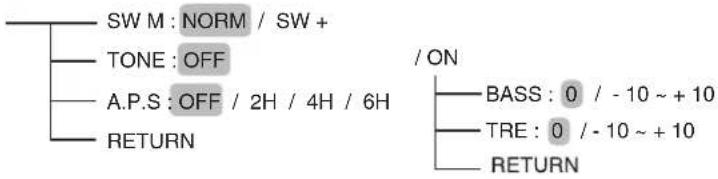
flowchart
graph TD
    A["SW M : NORM / SW +"] --> B["TONE : OFF"]
    B --> C["A.P.S : OFF / 2H / 4H / 6H"]
    C --> D["RETURN"]
    E["/ ON"] --> F["BASS : 0 / -10 ~ +10"]
    E --> G["TRE : 0 / -10 ~ +10"]
    E --> H["RETURN"]
- SW M(SUBWOOFER MODE) : To select the desired subwoofer mode.
• TONE : To adjust the tone (bass and treble) as desired. - A.P.S(AUTO POWER SAVE) : To set the power-off time as desired.
- RETURN: To return to the previous menu.
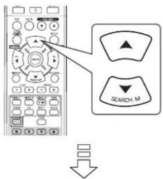
1. Press the CURSOR UP(▲)/DOWN(▼) buttons to select the desired item.
text_image
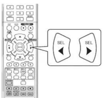
Diagram showing remote control buttons with directional indicators and a search icon labeled 'SEARCH_M'2. Press the CURSOR LEFT(◀)/RIGHT(▶) buttons to set the selected item as desired
text_image
SEL SELWhen selecting the SUBWOOFER MODE
- "SW +" mode is effective only when "F"(Front) and "C"(Center) are set to "LARGE" and "SW"(Subwoofer) is set to "YES" on the SPK SET menu. (For details, refer to "SETTING THE SPEAKER SETUP" on page 34.)
NORM: When the low frequency signals of channels set to "LARGE" are reproduced from those channels only. In this mode, the low frequency signals that are reproduced from the subwoofer channel is only the low frequency signals of LFE (from the multi-channel sources that contains LFE (Low Frequency Effects) channel, also called the ".1" channel) and the channels set to "SMALL".
SW +: When the low frequency signals of channels set to "LARGE" are reproduced simultaneously from those channels and the subwoofer channel. In this mode, the low frequency range expands more uniformly through the room, but depending on the size and shape of the room, interference may result in a decrease of the actual volume of the low frequency range.
When selecting the AUTO POWER SAVE
- The auto power save is a function that automatically turns the power off to enter the standby mode. When any button is not pressed for more than the time you set, it will function.
- You can set the power-off time as desired.
OFF 2H(Hour) 4H 6H (To turn off the function)
When selecting the TONE
OFF: To listen to a program source without the tone effect. ("DIR" lights up.)
ON : To adjust the tone for your taste. ("DIR" goes off.)
■When the TONE is set to ON to adjust the tone (bass and treble)
① Press the ENTER button to enter the tone setting mode.
text_image
ENTER② Press the CURSOR UP(▲)/DOWN(▼) buttons to select the desired tone.
text_image
SEARCH M
When selecting the BASS
BRASS: 0
③ Press the CURSOR LEFT(◀)/RIGHT(▶) buttons to adjust the selected tone as desired.
text_image
Diagram showing a remote control interface with labeled buttons and two 'SEL' button options- The tone level can be adjusted within the range of -10 \~ +10 dB.
- In general, we recommend the bass and treble to be adjusted to 0 dB (flat level).
- Extreme settings at high volume may damage your speakers.
SETTING THE INPUT
◆ INPUT
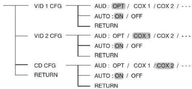
flowchart
graph TD
    A["VID 1 CFG"] --> B["AUD: OPT / COX 1 / COX 2 / ---"]
    A --> C["AUTO: ON / OFF"]
    A --> D["RETURN"]
    E["VID 2 CFG"] --> F["AUD: OPT / COX 1 / COX 2 / ---"]
    E --> G["AUTO: ON / OFF"]
    E --> H["RETURN"]
    I["CD CFG"] --> J["AUD: OPT / COX 1 / COX 2 / ---"]
    I --> K["AUTO: ON / OFF"]
    I --> L["RETURN"]
    M["RETURN"] --> N["OUTPUT"]
- AUD (AUDIO ASSIGN) : To assign the connected DIGITAL INs to the desired input.
- AUTO (AUTO SURROUND) : To select the auto surround mode or the manual surround mode.
-
RETURN: To return to the previous menu.
-
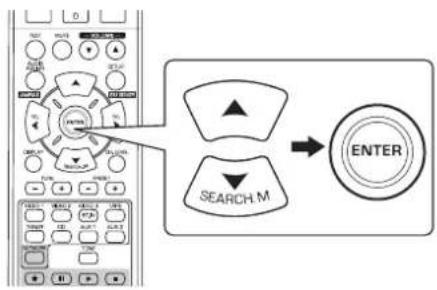
Press the CURSOR UP(▲)/DOWN(▼) buttons to select the desired input source, then press the ENTER button.
flowchart
graph TD
    A["User Interface"] --> B{Search Process}
    B --> C["ENTER"]
    style A fill:#f9f,stroke:#333
    style B fill:#ccf,stroke:#333
    style C fill:#cfc,stroke:#333

Example: When selecting the VIDEO 2
AUD: COXI
- Press the CURSOR UP(▲)/DOWN(▼) buttons to select the desired item.
text_image
Diagram showing remote control interface with labeled buttons and directional indicators- Press the CURSOR LEFT(◀)/RIGHT(▶) buttons to set the selected item as desired.
text_image
Diagram showing a remote control interface with two labeled buttons labeled 'SEL' pointing to different function keys.When selecting the AUDIO ASSIGN
- You should assign the connected DIGITAL INs to the desired of CD and VIDEO 1\~VIDEO 2. (For details, refer to "CONNECTING DIGITAL INS" on page 7.)
- You can select the desired of OPT (optical), COX 1(coaxial 1), COX 2(coaxial 2) and --- (analog).
Notes :
- In such a case that a DIGITAL IN is assigned to two input sources or more, when these input sources are selected, the digital audio signals can be heard from the same DIGITAL IN.
- When the HDMI IN connector is connected to your video component, the DIGITAL IN setting is invalid.
When selecting the AUTO SURROUND
- Depending on how to select a surround mode, you can select the auto surround mode or the manual surround mode.
OFF (Manual surround mode) : You can select the desired of different surround modes selectable for the signal being input with using the SURROUND MODE SELECT (> / <) buttons. (For details, refer to "when selecting the manual surround mode with pressing the AUTO/MANUAL button on the front panel" on page 17.)
ON(Auto surround mode): The optimum surround mode will be automatically selected depending on the signal format being input.
Notes
- When the SPEAKER button is set to off or "C(Center)" and "S(Surround)" are set to "NO", the auto surround mode is invalid.
- Even when the auto surround mode is selected and the same type of digital signal format is being input, the optimum surround mode may vary depending on whether the speaker type is set to "NO" or not.
- When the auto surround mode is selected, the surround modes other than the optimum surround mode cannot be selected.
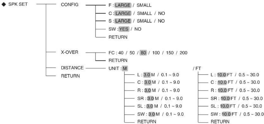
SETTING THE SPEAKER SETUP
• After you have installed this receiver and connected all the components, you should adjust the speaker settings for the optimum sound acoustics according to your environment and speaker layout.
- Even when you change speakers, speaker positions, or the layout of your listening environment, you should adjust the speaker settings, too.
flowchart
graph TD
    A["SPK SET"] --> B["CONFIG"]
    B --> C["F: LARGE / SMALL"]
    B --> D["C: LARGE / SMALL / NO"]
    B --> E["S: LARGE / SMALL / NO"]
    B --> F["SW: YES / NO"]
    B --> G["RETURN"]
    A --> H["X-OVER"]
    H --> I["FC: 40 / 50 / 80 / 100 / 150 / 200"]
    H --> J["RETURN"]
    A --> K["DISTANCE"]
    K --> L["UNIT: M"]
    L --> M["L: 3.0 M / 0.1 ~ 9.0"]
    L --> N["C: 3.0 M / 0.1 ~ 9.0"]
    L --> O["R: 3.0 M / 0.1 ~ 9.0"]
    L --> P["SR: 3.0 M / 0.1 ~ 9.0"]
    L --> Q["SL: 3.0 M / 0.1 ~ 9.0"]
    L --> R["SW: 3.0 M / 0.1 ~ 9.0"]
    L --> S["RETURN"]
    L --> T["/ FT"]
    T --> U["L: 10.0 FT / 0.5 ~ 30.0"]
    T --> V["C: 10.0 FT / 0.5 ~ 30.0"]
    T --> W["R: 10.0 FT / 0.5 ~ 30.0"]
    T --> X["SR: 10.0 FT / 0.5 ~ 30.0"]
    T --> Y["SL: 10.0 FT / 0.5 ~ 30.0"]
    T --> Z["SW: 10.0 FT / 0.5 ~ 30.0"]
    T --> AA["RETURN"]
- CONFIG (CONFIGURATION) : To select the sizes of the speakers that are connected.
- X-OVER (CROSSOVER) : To select the desired crossover frequency.
- DISTANCE: To enter the distance between the listening position and each speaker to set the delay time automatically for optimum surround playback.
- RETURN: To return to the previous menu.
When selecting the CONFIGURATION
- Press the CURSOR UP(▲)/DOWN(▼) buttons to select the "CONFIG", then press the ENTER button.
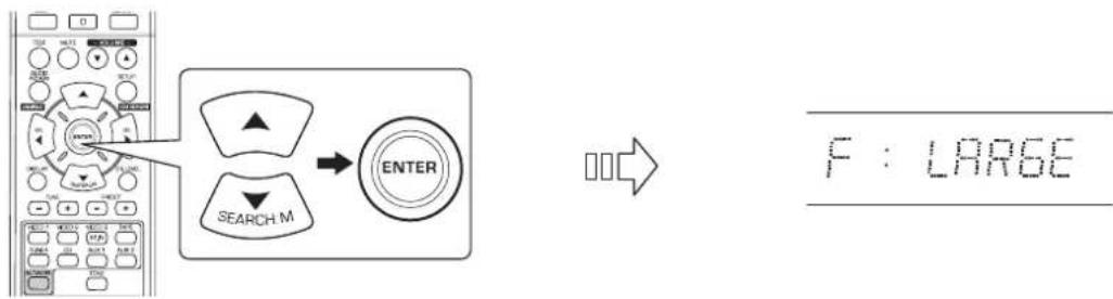
text_image
F : LARGE- Press the CURSOR UP(▲)/DOWN(▼) buttons to select the desired speaker.
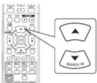
text_image
SEARCH_M- Press the CURSOR LEFT(◀)/RIGHT(▶) buttons to set the selected speaker as desired.
text_image
Diagram showing a remote control interface with two labeled 'SEL' buttons, one pointing to the main panel.- Depending on your speaker type, you can select one of these following speaker types.
- Front, Center and Surround speakers :
LARGE : Select this when connecting speakers that can fully reproduce sounds below crossover frequency.
SMALL : Select this when connecting speakers that can not fully reproduce sounds below crossover frequency. When this is selected, sounds below crossover frequency are sent to the subwoofer or speakers which are set to "LARGE" (when not using a subwoofer).
NO : Select this when no speakers are connected. When this is selected, sounds are sent to the speakers which are not set to "NO".
- Subwoofer :
YES : Select this to output LFE signals and bass frequencies of channels set to "SMALL" form the subwoofer.
NO : Select this when the subwoofer is not connected. The bass frequencies are output from other speakers.
Notes :
- When speakers are set to "SMALL", you should set their crossover frequency correctly according to their frequency characteristics. (For details, refer to "When selecting the CROSSOVER" on page 36.)
-
When the "F"(Front) is set to "SMALL", "C"(Center) and "S"(Surround) cannot be set to "LARGE" and the "SW"(Subwoofer) cannot be set to "NO".
-
Repeat the above steps 2 and 3 until the speakers are all set to the desired mode.
■About the speaker size
- Select "LARGE" or "SMALL" not according to the actual size of the speaker but according to the speaker's capacity for playing low frequency (bass sound below frequency set on the "CROSSOVER" menu) signals.
- If you do not know, try comparing the sound at both settings (setting the volume to a level low enough so as not to damage the speakers) to determine the proper setting.
When selecting the CROSSOVER
- When speakers are set to "SMALL", be sure to set their crossover frequency correctly according to their frequency characteristics.
- Press the CURSOR UP(▲)/DOWN(▼) buttons to select the "X-OVER", then press the ENTER button.
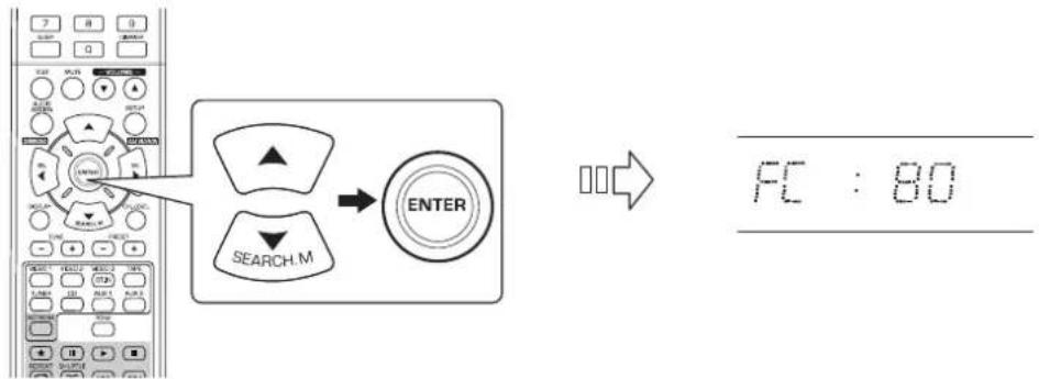
flowchart
graph LR
    A["Input"] --> B["Search M"]
    B --> C["ENTER"]
    C --> D["Output: FC : 80"]
- Press the CURSOR LEFT(◀)/RIGHT(▶) buttons to set the crossover frequency as desired.
text_image
Diagram showing a control panel with two labeled buttons labeled 'SEL' pointing to different function keys.- You can select the crossover frequency among 40, 50, 80, 100, 150 and 200 Hz.
■About the crossover frequency
- When speakers are set to "SMALL", low frequencies in those channels that are below the crossover frequency are to output from subwoofer or front speakers which are set to "LARGE" (when not using a subwoofer).
- Refer to the operating instructions of the speakers to be connected. If the frequency range of your speaker is 100 Hz\~20 kHz, the crossover frequency should be set to 100 Hz(or slightly higher).
When selecting the DISTANCE
- Press the CURSOR UP(▲)/DOWN(▼) buttons to select the "DISTANCE", then press the ENTER button.
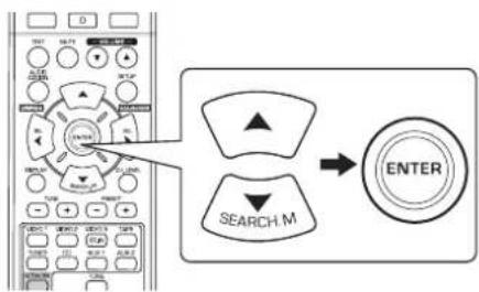
text_image
Diagram showing a remote control interface with two labeled buttons: one pointing up and one down, connected to an 'ENTER' button.

- Press the CURSOR UP(▲)/DOWN(▼) buttons to select the desired item.
text_image
SEARCH.MNote :
- You cannot select the speakers set to "NO".
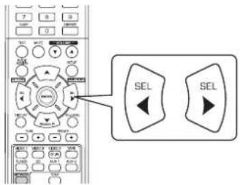
- Press the CURSOR LEFT(◀)/RIGHT(▶) buttons to set the selected item as desired.
text_image
Diagram showing a remote control interface with two labeled buttons labeled 'SEL' pointing to the left panel.■When selecting the desired unit
- You can select either "M (Meter)" or "FT (Feet)".
- Once a unit is selected, the distances are automatically changed in the selected unit.
■When setting the distance
- You can set the distance within the range of 0.1 \~ 9.0 meters in 0.1 meter intervals (or 0.5 \~ 30.0 feet in 0.5 feet intervals).
- Repeat the above steps 2 and 3 until the distances are all set as desired.
■ About the speaker distance
When enjoying multi-channel surround playback with Dolby Digital and DTS sources, etc., it is ideal that the center and surround speakers, etc. should be the same distance from the main listening position as the front speakers. By entering the distance between the listening position and each speaker, the delay times of center and surround speakers, etc. are automatically adjusted to create an ideal listening environment virtually as if the center and surround speakers, etc. were at their ideal locations respectively.
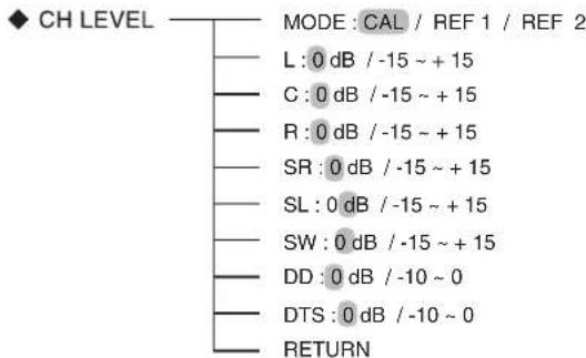
SETTING THE CH LEVEL
text_image
◆ CH LEVEL MODE : CAL / REF 1 / REF 2 L : 0 dB / -15 ~ + 15 C : 0 dB / -15 ~ + 15 R : 0 dB / -15 ~ + 15 SR : 0 dB / -15 ~ + 15 SL : 0 dB / -15 ~ + 15 SW : 0 dB / -15 ~ + 15 DD : 0 dB / -10 ~ 0 DTS : 0 dB / -10 ~ 0 RETURN■Note : Depending on the speaker settings ("NO", etc), some channels cannot be selected.
Adjusting the current channel level
- You can adjust the current channel levels as desired. These adjusted levels are just memorized into user's memory("CAL"), not into preset memory ("REF 1", "REF 2")
- After adjusting each channel level with test tone, adjust the channel levels either according to the program sources or to suit your tastes. (For details, refer to "Adjusting each channel level with test tone" on page 19.)
1. Press the CURSOR UP(▲)/DOWN(▼) buttons to select the desired channel.
text_image
SEARCH_MExample: When selecting Dolby Digital source's LFE

2. Press the CURSOR LEFT(◀)/RIGHT(▶) buttons to adjust the level of the selected channel or program source's LFE as desired.
text_image
4 5 6 7 8 9 0 MOV SET SELECT SELECT SELECT SELECT SELECT SELECT SELECT SELECT SELECT SELECT SELECT SELECT SELECT SELECT SELECT SELECT SELECT SELECT SELECT SELECT SELECT SELECT SELECT SELECT SELECT SELECT SELECT SELECT SELECT SELECT SELECT SELECT SELECT SELECT SELECT SELECT SELECT SELECT SELECT SELECT SELECT SELECT SELECT SELECT SELECT SELECT SELECT SELECT SELECT SELECT SEL SEL- The LFE level can be adjusted within the range of -10 \~ 0 dB and other channel levels within the range of -15 \~ +15 dB
- In general, we recommend the LFE level to be adjusted to 0 dB.(However, the recommended LFE level for some early DTS software is -10 dB.) If the recommended levels seem too high, lower setting as necessary.
3. Repeat the above steps 1 and 2 to adjust each channel level.
Memorizing the adjusted channel levels
- You can memorize the adjusted channel levels into preset memory("REF 1", "REF 2") and recall the memorized whenever you want.
- After performing the steps 1 \~ 3 in "Adjusting the current channel level" procedure on page 38, press the ENTER button.
text_image
ENTER
- Then "1" of "REF 1" indication flickers.
- Press the CURSOR LEFT(◀)/RIGHT(▶) buttons to select the desired preset memory, then press the ENTER button.
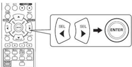
flowchart
graph LR
    A["SELE"] --> B["SELECT"]
    C["SELECT"] --> D["ENTER"]
- Each time the CURSOR LEFT(◀) or RIGHT(▶) button is pressed, "REF 1" or "REF 2" is selected.
- The adjusted channel levels have now been memorized into the selected memory.
Recalling the memorized channel levels
- Press the CURSOR UP(▲)/DOWN(▼) buttons to select the "MODE \~".
text_image
SEARCH, M
- "CAL" may be displayed instead of "REF 1" or "REF 2".
- Press the CURSOR LEFT(◀)/RIGHT(▶) buttons to select the desired one of REF 1 and REF 2.
text_image
Diagram showing a control panel with buttons and two labeled 'SEL' buttons, one pointing to the left panel.- Then the channel levels memorized into the selected preset memory are recalled.
SETTING THE PARAMETER
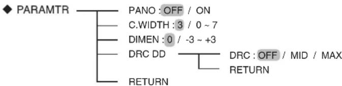
flowchart
graph TD
    A["PARAMTR"] --> B["PANO : OFF / ON"]
    A --> C["C.WIDTH : 3 / 0 ~ 7"]
    A --> D["DIMEN : 0 / -3 ~ +3"]
    A --> E["DRC DD"]
    E --> F["DRC : OFF / MID / MAX"]
    E --> G["RETURN"]
    E --> H["RETURN"]
- DOLBY PRO LOGIC II MUSIC PARAMETERS : To adjust the various Dolby Pro Logic II Music parameters for optimum (PANO(PANORAMA), C.WIDTH(CENTER) surround effect. WIDTH), DIMEN(DIMENSION))
- DRC DD(DYNAMIC RANGE COMPRESSION DOLBY DIGITAL) : To adjust the dynamic range compression that makes faint sound easier to hear at low volume levels.
- RETURN: To return to the previous menu.
When selecting "PANO", "C.WIDTH", "DIMEN"
- You can adjust the various Dolby Pro Logic II Music parameters for optimum surround effect.
Note:
- The parameter settings are valid only when listening in Dolby Pro Logic II Music mode.
- Press the CURSOR UP(▲)/DOWN(▼) buttons to select the desired parameter.
text_image
NEW SELECT ON OK Cancel SELECT ON SELECT ON SELECT ON SELECT ON SELECT ON SELECT ON SELECT ON SELECT ON SELECT ON SELECT ON SELECT ON SELECT ON SELECT ON SELECT ON SELECT ON SELECT ON SELECT ON SELECT ON SELECT ON SELECT ON SELECT ON SELECT ON SELECT ON SELECT ON SELECT ON SELECT ON SELECT ON SELECT ON SELECT ON SELECT ON SELECT ON SELECT ON SELECT ON SELECT ON- Press the CURSOR LEFT(◀)/RIGHT(▶) buttons to adjust the selected parameter as desired.
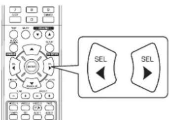
text_image
Diagram of a remote control interface with labeled buttons and a zoomed-in view showing 'SEL' function■When selecting the "PANO"(PANORAMA)
This mode extends the front stereo image to include the surround speakers for an exciting "wraparound" effect with side wall imaging. Select "OFF" or "ON"(default value:OFF).
■When selecting the "C. WIDTH"(CENTER WIDTH) control
This adjusts the center image so it may be heard only from the center speaker, only from the left/right speakers as a phantom image, or from all three front speakers to varying degrees. The control can be set in 8 steps from 0 to 7 (default value : 3).
■When selecting the "DIMEN"(DIMENSION)" control
This gradually adjusts the soundfield either towards the front or towards the rear. The control can be set in 7 steps from -3 to +3 (default value: 0).
- Repeat the above steps 1 and 2 to adjust other parameters.
When selecting "DRC DD"
- This function compresses the dynamic range of previously specified parts of the Dolby Digital sound track (with extremely high volume) to minimize the difference in volume between the specified and non-specified parts. This makes it easy to hear all of the sound track when watching movies at night at low levels.
Notes:
- This setting is valid only when the digital signals from the Dolby Digital program source are being input. - In some Dolby Digital softwares, this setting may not be valid.
- Press the CURSOR UP(▲)/DOWN(▼) buttons to select "DRC DD", then press the ENTER button.
text_image
ENTER SEARCH.M- Press the CURSOR LEFT(◀)/RIGHT(▶) buttons to adjust the dynamic range compression as desired.
text_image
Diagram showing a remote control interface with labeled buttons and two 'SEL' buttons, one pointing to the main panel.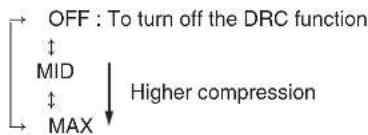
flowchart
graph TD
    A["OFF : To turn off the DRC function"] --> B["MID"]
    B --> C["Higher compression"]
    B --> D["MAX"]
    D --> E["Output"]
SETTING THE HDMI
flowchart
graph TD
    A["HDMI"] --> B["HDMI: AMP / THRU"]
    A --> C["CEC: OFF / ON"]
    A --> D["PWR: OFF / ON"]
    A --> E["RETURN"]
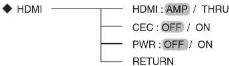
- HDMI(HDMI AUDIO OUT) : To output the digital audio signals from the HDMI MONITOR OUT connector.
- CEC(HDMI CONTROL) : To link operations with components connected to HDMI connectors and compatible with HDMI control.
- PWR(POWER CONTROL) : To link the power ON/OFF status of this unit to components.
- RETURN: To return to the previous menu.
1. Press the CURSOR UP(▲)/DOWN(▼) buttons to select the desired item.
text_image
SEARCH M2. Press the CURSOR LEFT(◀)/RIGHT(▶) buttons to set the selected item as desired.
text_image
Diagram showing a remote control interface with two 'SEL' buttons and a zoomed-in view of the left panel.When selecting the HDMI AUDIO OUT
- The HDMI connection can carry uncompressed digital video signals and digital audio signals.
Depending on whether the digital audio signals input into the HDMI IN are output from the HDMI MONITOR OUT of this receiver or not, you should set the HDMI AUDIO OUT correctly.
AMP: Not to output the HDMI digital audio signals from the HDMI MONITOR OUT of this receiver, meaning these signals are heard from the speakers connected to this receiver.
↓
THRU : To output the HDMI digital audio signals from the HDMI MONITOR OUT, meaning these signals are heard from the speakers of your TV.
Note:
- When the HDMI AUDIO OUT is set to THRU, no sound will not be heard from the speakers connected to this unit.
When selecting the HDMI CONTROL
- The HDMI control function allows input selection of this unit to be interlocked with the operation of the connected components. OFF: Not to use the HDMI CONTROL function.
↑
ON : To use the HDMI CONTROL function.
- When the HDMI CONTROL is set to ON, you can also use the ARC(Audio Return Channel) function, enabling the TV to send the audio signals to this receiver via a HDMI cable.
Notes:
- The HDMI control function may not work depending on the connected component and its settings.
• To use the ARC function, the TV that supports the ARC function is required. - For details on HDMI CONTROL and POWER CONTROL, refer to "CONFIRMING THE HDMI FUNCTION" on page 28.
When selecting the POWER CONTROL
- The Power control function allows the power status of this unit to be interlocked with the power ON/OFF and start of playback of the connected components.
OFF : Not to use the POWER CONTROL function.
ON : To use the POWER CONTROL function.
Note:
- The POWER CONTROL can be set only when the HDMI CONTROL is set to ON.
Troubleshooting Guide
If a fault occurs, run through the table below before taking your receiver for repair.
If the fault persists, attempt to solve it by switching the receiver off and on again. If this fails to resolve the situation, consult your dealer. Under no circumstances should you attempt to repair the receiver yourself. This could void the warranty.
| PROBLEM POSSIBLE CAUSE REMEDY | ||
| No power | The AC input cord is disconnected.Poor connection at AC wall outlet or the outlet is dead or off. | Connect cord securely.Check the outlet using a lamp or another appliance. |
| No sound | The speaker wires are disconnected.The master volume is adjusted too low.The MUTE button is pressed to ON.Incorrect selection of input source.Incorrect connections between the components.The HDMI AUDIO OUT is set to THRU.The settings related to audio are set incorrectly. | Check the speaker connections.Adjust the master volume.Press the MUTE button to cancel the muting effect.Select the desired input source correctly.Make connections correctly.Set it to AMP. (For details, refer to "When selecting the HDMI AUDIO OUT" on page 42.)Set the settings correctly. (For details, refer to "SETTING THE INPUT" on page 33.) |
| No sound from the surround speakers | Surround mode is switched off(stereo mode).Master volume and surround level are too low.Monaural source is used.Surround speaker setting is "NO". | Select a surround mode.Adjust master volume and surround level.Select a stereo or surround source.Select the desired surround speaker setting. |
| No sound from the center speaker | Stereo mode, etc is selected.Center speaker setting is "NO".Master volume and center level are too low. | Select the desired surround mode.Select the desired center speaker setting.Adjust master volume and center level. |
| No picture | Video connections between this unit and the monitor TV are not made correctly.Incorrect selection of input source on the monitor TV. | Make proper video connections.Select the input source correctly. |
| No picture with an HDMI connection | HDMI connection between this unit and the monitor TV are not made correctly.The monitor TV or other equipments do not support HDCP. | Make proper HDMI connection.This unit will not output video signal unless the connected equipments supports HDCP. |
| Noise or distorted picture | Video format of your monitor TV, DVD player, etc. is different from PAL. | Change the video format to PAL. |
| Stations cannot be received | No antenna is connected.The desired station frequency is not tuned in.Antenna is in wrong position. | Connect an antenna.Tune in the desired station frequency.Move antenna and retry tuning. |
| Preset stations cannot be received | An incorrect station frequency has been memorized.The memorized stations are cleared. | Memorize the correct station frequency.Memorize the stations again. |
| Poor FM reception | No antenna is connected.The antenna is not positioned for the best reception.Weak signals. | Connect an antenna.Change the position of the antenna.Install an outdoor FM antenna. |
| Continuous or intermittent hissing noise during AM reception, especially at night. | Noise is caused by motors, fluorescent lamps or lightning, etc. | Keep the receiver away from noise sources.Install an outdoor AM antenna. |
| Remote control unit does not operate. | Batteries are not loaded or exhausted.The remote sensor is obstructed. | Replace the batteries.Remove the obstacle. |
Specifications
■ AMPLIFIER SECTION
• Power output, stereo mode, 6 Ω, THD 0.7%, 40 Hz\~20 kHz | 2x100 W
• Total harmonic distortion, 6 Ω, 100 W, 1 kHz | 0.05 %
- Intermodulation distortion
60 Hz : 7 kHz= 4 : 1 SMPTE, 6 Ω, 100 W | 0.1 %
- Input sensitivity, 47 kΩ
Line (CD, TAPE, VIDEO) | 250 mV
- Signal to noise ratio, IHF "A" weighted Line (CD, TAPE, VIDEO) | 95 dB
- Frequency response
Line (CD, TAPE, VIDEO), 20 Hz\~50 kHz I +0 dB, -3 dB
- Output level
TAPE REC, 2.2 kΩ | 250 mV
PRE OUT (Subwoofer), 1 kΩ | 1.5 V
- Bass/Treble control, 100 Hz/10 kHz | ±10 dB
- Surround mode, only channel driven
Front power output, 6 Ω, 1 kHz, THD 0.7 % | 100 W / 100 W
Center power output, 6 Ω, 1 kHz, THD 0.7 % | 100 W
Surround power output, 6 Ω, 1 kHz, THD 0.7 % | 100 W / 100 W
DIGITAL AUDIO SECTION
• Sampling frequency | 32, 44.1, 48, 96 kHz
- Digital input level
Coaxial, 75 Ω | 0.5 Vp-p
Optical, 660 nm | -15\~-21 dBm
VIDEO SECTION
• Video format | PAL
- Input sensitivity (=Output level), 75 Ω
Video (Composite (normal)) | 1 Vp-p
- HDMI connector | 19 pin
■ FM TUNER SECTION
- Tuning frequency range | 87.5\~108 MHz
• Usable sensitivity, THD 3%, S/N 26 dB | 12.8 dBf
• 46 dB quieting sensitivity, mono/stereo | 20.2 / 45.3 dBf
• Signal to noise ratio, 65 dBf, mono/stereo | 55 / 50 dB
• Total harmonic distortion, 65 dBf, 1 kHz, mono/stereo | 0.5 / 1.0 %
• Frequency response, 30 Hz\~12 kHz | ±3.0 dB
• Stereo separation, 1 kHz | 30 dB
• Capture ratio | 4 dB
• IF rejection ratio | 80 dB
■ AM TUNER SECTION
- Tuning frequency range | 522\~1611 kHz
• Usable sensitivity | 500 μV/m
• Signal to noise ratio | 40 dB - Selectivity | 25 dB
GENERAL
• Power supply | 230 V \~ 50 Hz
• Power consumption | 200 W
- Dimensions (WxHxD, including protruding parts) | 435x143x359 mm (17-3/8x5-5/8x14-1/8 inches)
• Weight (Net) | 8.6 kg (19 lbs)
Note: Design and specifications are subject to change without notice for improvements.
Einleitung
BITTE LESEN SIE DIESE HINWEISE VOR INBETRIEBNAHME DES GERÄTS


Systemanschlüsse | 4
Bedienelemente Frontblende | 10
Fernbedienung | 12
natural_image
Line drawing of a remote control panel with battery and switch (no text or symbols)FM ST → FM MONO → AM
O(ptical)→ C(oaxial) 1 → C(oaxial) 2 → A(nalog)
natural_image
Simple line drawing of a pair of headphones connected to a ring-shaped earphone (no text or symbols)text_image
Diagram showing a remote control interface with two 'SEL' buttons and a zoomed-in view of the left panel.NEWS
text_image
7 B 6 SLUT D SETUP SETUP SETUP SYSTEMtext_image
Diagram showing a remote control with two 'SEL' buttons and an arrow pointing to the center of the main panel.text_image
Diagram of a remote control interface with labeled buttons and directional arrows pointing to 'SEL' buttons.text_image
Control panel interface with labeled buttons and a search icon, showing navigation arrows and function labelstext_image
Diagram showing a remote control with two labeled buttons labeled 'SEL' pointing to different function keys.text_image
Diagram showing a remote control interface with two 'SEL' buttons and a zoomed-in view of the left panel.text_image
Diagram showing a remote control interface with two 'SEL' buttons and a zoomed-in view of the left panel.text_image
4 5 6 7 8 9 0 1 2 3 SET LET SET SET LET SET SET LET SET SET LET SET SEL SELtext_image
Diagram showing a remote control interface with two 'SEL' buttons and directional arrows pointing to the left panel.text_image
Diagram showing a remote control interface with labeled buttons and two 'SEL' buttons, one pointing to the main panel.text_image
Diagram showing a remote control with labeled buttons and two directional indicators: one with an arrow pointing to the left panel and another with a downward arrow labeled 'SEARCH_M'.text_image
Diagram showing a remote control interface with two labeled 'SEL' buttons, one pointing to the left panel.text_image
Diagram showing a remote control with two labeled buttons labeled 'SEL' pointing to different function keys.natural_image
Line drawing of a battery being inserted into a rectangular device (no text or symbols)text_image
AUDIO ASSIGN AUDIO ASSIGNtext_image
MASTER VOLUME DOWN UP VOLUMEnatural_image
Line drawing of a pair of headphones connected by a cord, no text or symbols present■DTS Digital Surround
OÍR EMISIONES RDS (SÓLO FM)
text_image
Diagram showing a control panel with labeled buttons and two 'SEL' buttons, one pointing to the middle button.NEWS
text_image
Diagram showing a remote control interface with labeled buttons and two 'SEL' buttons, one pointing to the right button.text_image
7 8 B 0.25 D 100 M A L C E F G H I J K L M N O P Q R S T U V W X Y Z A B C D E F G H I J K L M N O P Q R S T U V W X Y Z A B C D E F G H I J K L M N O P Q R S T U V W X Y Ztext_image
Diagram showing remote control with labeled buttons and a search icon, likely from an electronics or diagnostic software interface.text_image
Diagram showing a remote control interface with two 'SEL' buttons and an arrow pointing to the left button.text_image
Diagram showing a remote control interface with two labeled 'SEL' buttons, one pointing to the main panel.text_image
Diagram of a remote control interface with labeled buttons and two 'SEL' buttons, one pointing to the right button.text_image
? B 0 OFF 0 ON ON ON ON ON ON ON ON ON ON ON ON ON ON ON ON ON ON ON ON ON ON ON ON ON ON ON ON ON ON ON ON ON ON ON ON ON ON ON ON ON ON ON ON ON ON ON ON ON ON ONE ONE ONE ONE ONE ONE ONE ONE ONE ONE ONE ONE ONE ONE ONE ONE ONE ONE ONE ONE ONE ONE ONE ONE ONE ONE ONE ONE ONE ONE ONE ONE ONE ONE ONE ONE ONE ONE ONE ONE ONE ONE ONE ONE ONE ONE■Nota:
text_image
Diagram showing a remote control interface with two 'SEL' buttons and directional arrows pointing to the left panel.text_image
Diagram showing a remote control interface with two labeled 'SEL' buttons, one pointing to the left panel.text_image
ENTER MODE:REF:text_image
Diagram showing a remote control interface with two 'SEL' buttons and an arrow pointing to the center of the 'SEL' button.text_image
Diagram showing a remote control interface with two 'SEL' buttons and a zoomed-in view of the left panel.text_image
Diagram showing a remote control interface with two labeled 'SEL' buttons, one pointing to the main panel.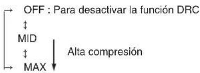
flowchart
graph TD
    A["OFF : Para desactivar la función DRC"] --> B["MID"]
    B --> C["MAX"]
    C --> D["Alta compresión"]
AJUSTANDO EL HDMI

flowchart
graph TD
    A["HDMI"] --> B["AMP / THRU"]
    A --> C["CEC / OFF / ON"]
    A --> D["PWR / OFF / ON"]
    A --> E["RETURN"]
text_image
2,3 4 8 3 5 1 2 7 SHERWOOD RD-6506 A JOOYLD00000000000000000000000000000000000000000000000000000000000000000000000 N18041 R L R L R L R L R L R L R L R L R L R L R L R L R L R L R L R L R L R L R L R L R L R L R L R L R L R L R L R L R L R L R L R L R L R L 1 2 3 6 CAUTION1. RACCORDEMENT DES ANTENNES
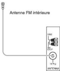
text_image
Antenne FM intérieure GND LOOP ANTENNA- Retirez le couvercle.

natural_image
Line drawing of a remote control with battery and switch (no text or symbols)text_image
AUDIO ASSIGN RETURN OU AUDIO ASSIGNtext_image
MASTER VOLUME DOWN UP OU — VOLUME —natural_image
Line drawing of a pair of headphones connected by a cable (no text or symbols)text_image
Diagram showing a remote control interface with two 'SEL' buttons and an arrow pointing to the left panel.■DTS Digital Surround
text_image
STEREO OU STEREOtext_image
ENTER/MEMO OUECOUTER DES EMISSIONS RDS (FM UNIQUEMENT)
text_image
SEARCH, Mtext_image
Diagram showing a control panel with labeled buttons and two 'SEL' buttons, one pointing to the middle button.NEWS
- A chaque pression sur ces touches, un type de programme différent est sélectionné. (NEWS, AFFAIRS, INFO, SPORT, EDUCATE, DRAMA, CULTURE, SCIENCE, VARIED, POP M, ROCK M, EASY M, LIGHT M, CLASSICS, OTHER M, WEATHER, FINANCE, CHILDREN, SOCIAL, RELIGION, PHONE IN, TRAVEL, LEISURE, JAZZ, COUNTRY, NATION M, OLDIES, FOLK M, DOCUMENT) (ACTUALITES, POLITIQUE, INFOS, SPORT, EDUCATION, THEATRE, CULTURE, SCIENCES, DIVERS, POP, ROCK, EASY LISTENING, LEGER, CLASSIQUE, AUTRES, METEO, FINANCE, ENFANTS, SOCIAL, RELIGION, LIGNE OUVERTE, VOYAGES, LOISIRS, JAZZ, PAYS, NATION M, NOSTALGIE, FOLK, DOCUMENTAIRE) - Si "SEARCH" disparaît, appuyez de nouveau sur la touche SEARCH MODE.
text_image
DISPLAY Sherwoodtext_image
Diagram showing a remote control interface with directional buttons and a search icon labeled 'SEARCH.M'text_image
Diagram of a remote control with labeled buttons and directional indicators, including 'SEARCH M' and directional arrows.text_image
Diagram of a remote control interface with labeled buttons and directional arrows pointing to 'SEL' buttons.text_image
Diagram showing a control panel with labeled buttons and two 'SEL' buttons, one pointing to the main panel.flowchart
graph TD
    A["User Interface"] --> B["Search M"]
    B --> C["ENTER"]
    C --> D["Down Arrow"]
text_image
Diagram showing a remote control interface with two labeled buttons labeled 'SEL' pointing to different function keys.text_image
Diagram showing a remote control with labeled buttons and a zoomed-in view of two 'SEL' buttons.text_image
Diagram showing a remote control interface with two 'SEL' buttons and a selection dialog box, likely illustrating a media or audio setup.text_image
Diagram showing a remote control interface with two labeled buttons labeled 'SEL' pointing to different function keys.text_image
Diagram showing a remote control interface with two labeled 'SEL' buttons, one pointing to the left panel.text_image
Diagram of a remote control interface with labeled buttons and directional arrows pointing to 'SEL' buttons