R607 - Receiver SHERWOOD - Free user manual and instructions
Find the device manual for free R607 SHERWOOD in PDF.
Frequently Asked Questions - R607 SHERWOOD
User questions about R607 SHERWOOD
0 question about this device. Answer the ones you know or ask your own.
Ask a new question about this device
Download the instructions for your Receiver in PDF format for free! Find your manual R607 - SHERWOOD and take your electronic device back in hand. On this page are published all the documents necessary for the use of your device. R607 by SHERWOOD.
USER MANUAL R607 SHERWOOD
R&TTE Directive 1999/5/EC

This symbol indicates the presence of uninsulated “dangerous voltage” within the product's enclosure that may be of sufficient magnitude to constitute a risk of electric shock.

This symbol indicates important operating and maintenance (servicing) instructions in the literature accompanying the appliance.
WARNING: TO REDUCE THE RISK OF FIRE OR ELECTRIC SHOCK, DO NOT EXPOSE THIS APPLIANCE TO RAIN OR MOISTURE.
CAUTION
- Leave space around the unit for sufficient ventilation.
- Avoid installation in extremely hot or cold locations, or in an area that is exposed to direct sunlight or heating equipment.
- Keep the unit free from moisture, water, and dust.
- Do not let foreign objects in the unit.
- Keep the ventilation openings clear of items, such as newspapers, linens, or curtains.
- Keep open flame from candles or other sources away from the unit.
- Observe the local regulations regarding disposal of packaging materials, exhausted batteries and old equipment.
- Do not expose the unit to dripping or splashing, or place objects filled with liquids such as vases.
- Do not let insecticides, benzene, or thinner come in contact with the unit.
- Never disassemble or modify the unit in any way.
Notes on the AC power cord and the wall outlet
- The unit remains connected to AC power as long as it is plugged into the wall outlet, even if the unit has been turned off.
- To completely disconnect this product from AC power, disconnect the plug from the wall socket outlet.
- When setting up this product, make sure that the AC outlet you are using is easily accessible.
- Disconnect the plug from the wall outlet when not using the unit for long periods of time.
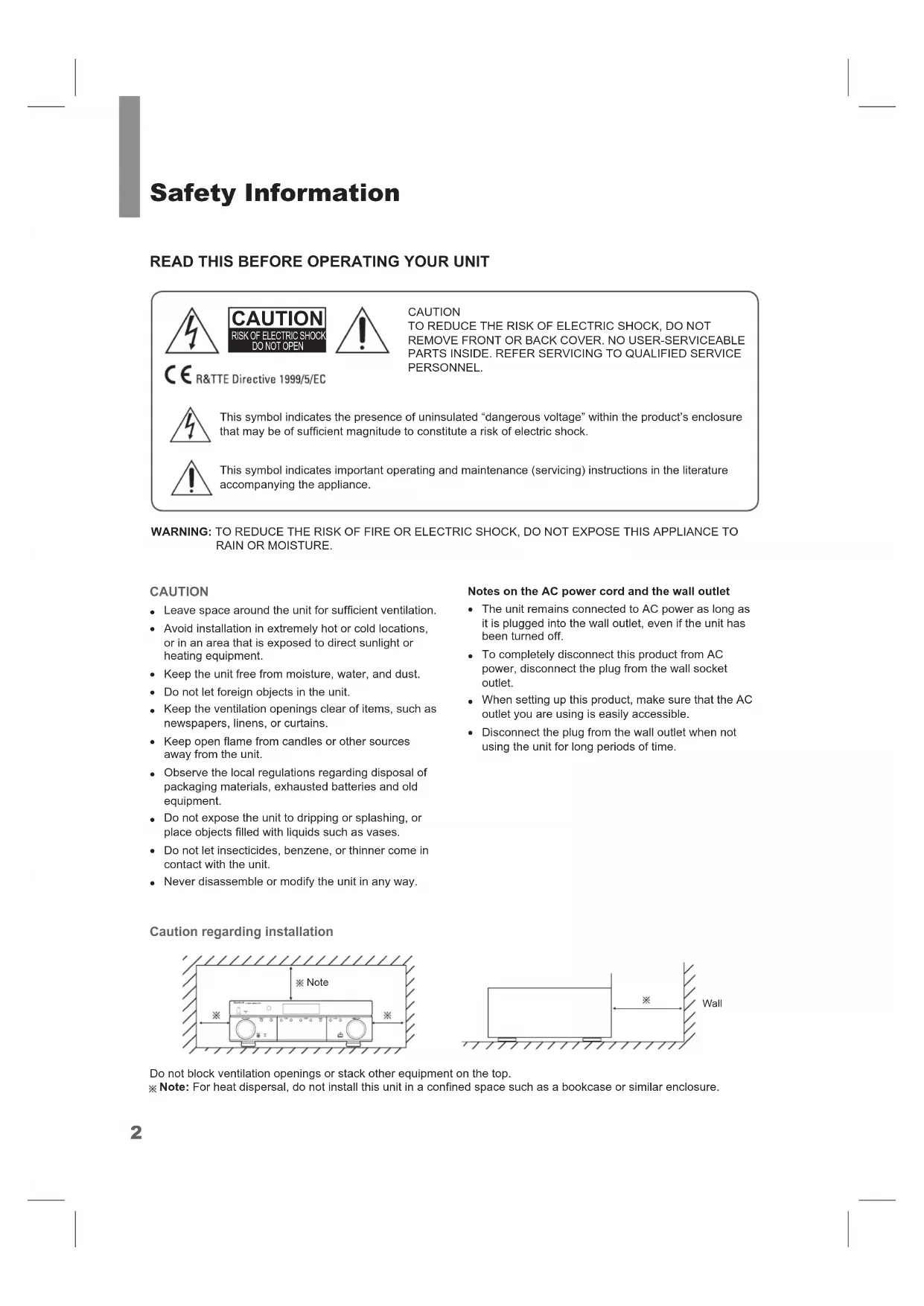
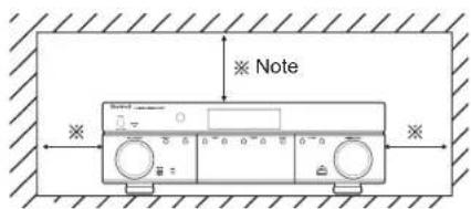
Caution regarding installation
text_image
Note
text_image
※ WallDo not block ventilation openings or stack other equipment on the top.
※ Note: For heat dispersal, do not install this unit in a confined space such as a bookcase or similar enclosure.
FCC Notice
This equipment has been tested and found to comply with the limits for a Class B digital device, pursuant to Part 15 of the FCC Rules. These limits are designed to provide reasonable protection against harmful interference in a residential installation. This equipment generates, uses and can radiate radio frequency energy and, if not installed and used in accordance with the instructions, may cause harmful interference to radio communications. However, there is no guarantee that interference will not occur in a particular installation. If this equipment does cause harmful interference to radio or television reception, which can be determined by turning the equipment off and on, the user is encouraged to try to correct the interference by one or more of the following measures:
Reorient or relocate the receiving antenna.
Increase the separation between the equipment and the receiver.
Connect the equipment to an outlet on a circuit different from that to which the receiver is connected.
Consult the dealer or an experienced radio/TV technician for help.
This device complies with part 15 of the FCC Rules. Operation is subject to the following two conditions:
(a) This device may not cause harmful interference, and
(b) This device must accept any interference received, including interference that may cause undesired operation.
(FCC Part 15.21) Caution: changes or modifications not expressly approved by the party responsible for compliance could void the user's authority to operate the equipment.
Important Safety Instructions
1 Read these instructions.
2 Keep these instructions.
3 Heed all warnings.
4 Follow all instructions.
5 Do not use this apparatus near water.
6 Clean only with dry cloth.
7 Do not block any ventilation openings. Install in accordance with the manufacturer's instructions.
8 Do not install near any heat sources such as radiators, heat registers, stoves, or other apparatus (including amplifiers) that produce heat.
9 Do not defeat the safety purpose of the polarized or grounding-type plug. A polarized plug has two blades with one wider than the other. A grounding type plug has two blades and a third grounding prong. The wide blade or the third prong are
provided for your safety. If the provided plug does not fit into your outlet, consult an electrician for replacement of the obsolete outlet.
10 Protect the power cord from being walked on or pinched particularly at plugs, convenience receptacles, and the point where they exit from the apparatus.
11 Only use attachments/accessories specified by the manufacturer.
12 Use only with the cart, stand, tripod, bracket, or table specified by the manufacturer, or sold with the apparatus. When a cart is used, use caution when moving the cart/ apparatus combination to avoid injury from tip-over.
13 Unplug this apparatus during lightning storms or when unused for long periods of time.
14 Refer all servicing to qualified service personnel. Servicing is required when the apparatus has been damaged in any way, such as power-supply cord or plug is damaged, liquid has been spilled or objects have fallen into the apparatus, the apparatus has been exposed to rain or moisture, does not operate normally, or has been dropped.

dts-HD
Master Audio
Manufactured under license under U.S. Patent Nos: 5,956,674; 5,974,380;
6,226,616; 6,487,535; 7,212,872; 7,333,929; 7,392,195; 7,272,567 & other U.S. and worldwide patents issued & pending. DTS-HD, the Symbol, & DTS-HD and the Symbol together are registered trademarks & DTS-HD Master Audio is a trademark of DTS, Inc. Product includes software. © DTS, Inc. All Rights Reserved.

TRUEHD
Manufactured under license from Dolby Laboratories. Dolby, Pro Logic, and the double-D symbol are trademarks of Dolby Laboratories.

HIGH DEFINITION MULTIMEDIA INTERFACE
HDMI, the HDMI Logo, and High-Definition Multimedia Interface are trademarks or
registered trademarks of HDMI Licensing LLC in the United States and other contries.
* DTS-HD Master Audio and Dolby TrueHD is applicable only for R-607.
Table of Contents
2 SAFETY INFORMATION
5 GETTING STARTED
5 Front Panel
5 Rear Panel
6 Remote Control
7 Placement
8 CONNECTIONS
8 Connect Your Speakers
8 Connect Your Subwoofer
9 Connect Your TV or Video Display
10 Connect Your Audio and Video Source Devices
14 Connect the Tuner Antennas
14 Connect to AC Power
14 Install the Batteries in the Remote Control
15 SETUP
15 Turn On the AVR
15 Configure the AVR for Your Speakers
17 OPERATION
17 Operating Your AVR
17 Listening to FM and AM Radio
18 Listening to Media on a USB Device
18 Selecting a Surround Mode
19 Advanced Functions
21 TROUBLESHOOTING
22 SPECIFICATIONS
Getting Started
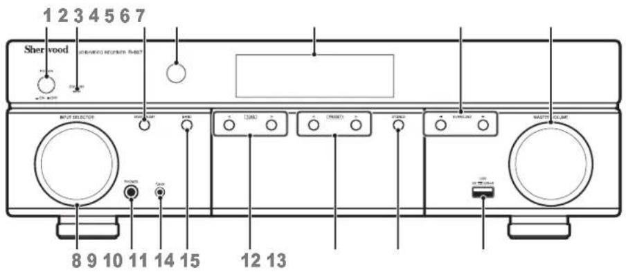
Front Panel
text_image
1 2 3 4 5 6 7 Sherwood air conditioner fan? 8 9 10 11 14 15 12 131 Main Power Switch
2 Standby Indicator
3 On/Standby Switch
4 IR Sensor
5 Display
6 Surround Select Buttons
7 Master Volume Control
8 Input Selector
9 Headphone Connector
10 F.AUX Input Connector
11 Band Select Button
12 Tuning Up/Down Buttons
13 Preset Select Buttons
14 Stereo Mode Button
15 USB Port
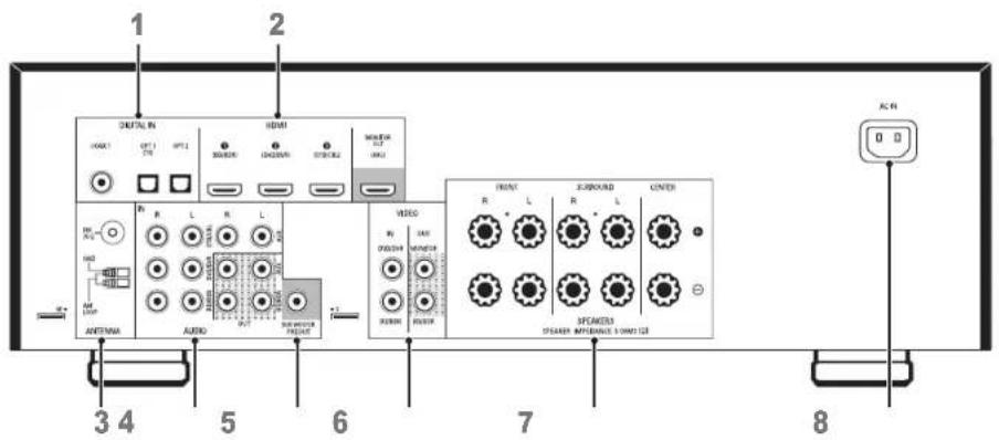
Rear Panel
text_image
1 2 3 4 5 6 7 8 OUTPUT AUDIO VIDEO R L R L R L R L R L R L R L R L R L R L R L R L R L R L R L R L R L R L R L R L R L R L R L R L R L R L R L R L R L R L R L R L R L R L1 Digital Audio Connectors
2 HDMI Connectors
3 Tuner Antenna Connectors
4 Analog Audio Connectors
5 Subwoofer Connector
6 Composite Video Connectors
7 Speaker Connectors
8 AC Input Connector
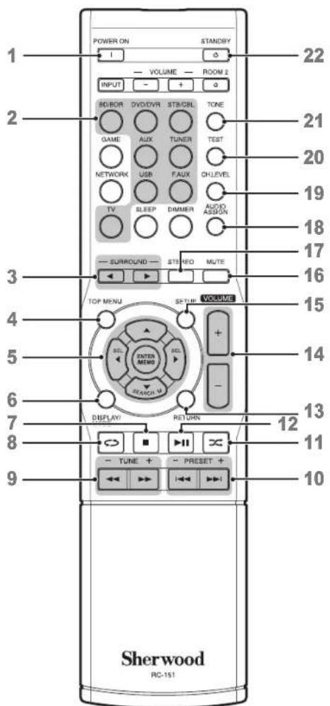
Remote Control
text_image
POWER ON STANDBY 1 VOLUME ROOM 2 INPUT + 2 SB/BOR DVD/DVR ST/B/CBL TONE GAME AUX TUNER TEST NETWORK USB FAUX CHLEVEL TV SLEEP DIMMER AUDIO ASSIGN 3 SURROUND STUDIO MUTE TOP MENU VOLUME 5 ENTER MENU + - SEARCH U 6 DISPLAY RETURN 7 TUNE + PRESET + 8 10 Sherwood RC-151 121 Power On Button
2 Source Select Buttons
3 Surround Select Buttons
(The GAME and NETWORK buttons are not available.)
4 Top Menu Button
5 ▲/▼/◄/► Select Buttons
ENTER/MEMO Enter/Memory Button
SEARCH.M RDS Search Button
(* The SEARCH.M button is available only in models that are distributed in Europe.)
6 Display/Mode Button
7 Stop Button
8 Repeat Button
9 Tuning Up/Down Buttons
Rewind/Fast forward Buttons
10 Preset Station Up/Down Buttons
Previous/Next Buttons
11 Random Button
12 Play/Pause Button
13 Return Button
14 Volume Up/Down Buttons
15 Setup Menu Button
16 Mute Button
17 Stereo Mode Button
18 Audio Assign Button
19 Channel Level Button
20 Test Tone Sequence Button
21 Tone Control Button
22 Standby Button
Placement
Place Your Speakers
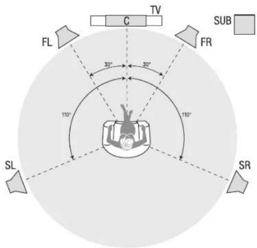
Determine the locations for your system's speakers according to their manufacturer's directions and the layout of your listening room. Use the illustration below as a guide for 5.1-channel systems.
To create the most realistic surround-sound environment possible, you should place your speakers in a circle with the listening position at its center. You should angle each speaker so it directly faces the listening position. Use the diagram below as a guide.
text_image
TV C FL 30° 30° FR 110° 110° SL SR SUBPlacing the Left, Center and Right Speakers
Place the center speaker either on top of, below or mounted on the wall above or below the TV or video-display screen. Place the front left and right speakers along the circle, about 30 degrees from the center speaker and angled toward the listener.
Place the front left, front right and center speakers at the same height, preferably at about the same height as the listener's ears. The center speaker should be no more than 2 feet (0.6m) above or below the left/right speakers. If you're using only two speakers with your AVR, place them in the front left and front right positions.
Placing the Surround Speakers
You should place the left and right surround speakers approximately 110 degrees from the center speaker, slightly behind and angled toward the listener.
Alternatively, you can place them behind the listener, with each surround speaker facing the opposite-side front speaker. You should place the surround speakers 2 feet - 6 feet (0.6m - 1.8m) higher than the listener's ears.
Placing the Subwoofer
Because a room's shape and volume can have a dramatic effect on a subwoofer's performance, it is best to experiment with placement so that you will find the location that produces the best results in your particular listening room. With that in mind, these rules will help you get started:
- Placing the subwoofer next to a wall generally will increase the amount of bass in the room.
- Placing the subwoofer in a corner generally will maximize the amount of bass in the room.
- In many rooms, placing the subwoofer along the same plane as the left and right speakers can produce the best integration between the sound of the subwoofer and that of the left and right speakers.
- In some rooms, the best performance could even result from placing the subwoofer behind the listening position. A good way to determine the best location for the subwoofer is by temporarily placing it in the listening position and playing music with strong bass content. Move around to various locations in the room while the system is playing (putting your ears where the subwoofer would be placed), and listen until you find the location where the bass performance is best. Place the subwoofer in that location.
Connections

Caution
- Before making any connections to the audio/video receiver, ensure that the AVR's AC cord is unplugged from the AVR and the AC outlet. Making connections with the AVR plugged in and turned on could damage the speakers.

Connect Your Speakers
How to use the AVR's speaker terminals
1
Unscrew Cap

2
Insert Bare Wire
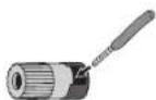
3
Tighten Cap
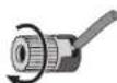
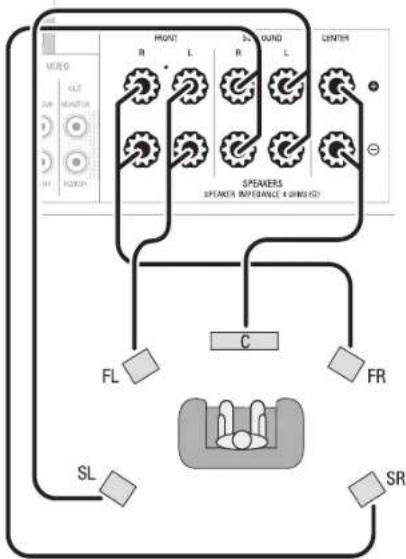
Always connect the colored (+) terminal on the AVR to the (+) terminal on the speaker (usually red), and the black (−) terminal on the AVR to the (−) terminal on the speaker (usually black).

Caution
- Make sure the (+) and (−) bare wires do not touch each other or the other terminal. Touching wires can cause a short circuit that can damage your AVR.
Connect the speakers as shown in the illustration.
flowchart
graph TD
    A["Speaker"] --> B["FR"]
    A --> C["SL"]
    A --> D["FL"]
    A --> E["SR"]
    A --> F["C"]
    A --> G["SPEAKER"]
    A --> H["SPEAKER REFERENCE & SING ID"]
    A --> I["Central"]
    style A fill:#f9f,stroke:#333
    style B fill:#ccf,stroke:#333
    style C fill:#cfc,stroke:#333
    style D fill:#fcc,stroke:#333
    style E fill:#cff,stroke:#333
    style F fill:#ffc,stroke:#333
    style G fill:#cfc,stroke:#333
    style H fill:#fcc,stroke:#333
    style I fill:#cfc,stroke:#333
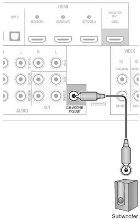
Connect Your Subwoofer
Use a single RCA audio cable to connect the AVR's Subwoofer Pre-Out connector to your subwoofer. Consult your subwoofer's user manual for specific information about making connections to it.
Rear Panel
text_image
HDMI OPT 2 (BD/BOI) (DVD/DVR) (STB/CBL) MONITOR OUT (AICI) R L R L STICKEL DVD/DVD/R AUDIO OUT SUBWOOFER PREOUT VIDEO IN DV/DVD OL MON BD/BOI BDI SubwooferConnect Your TV or Video Display
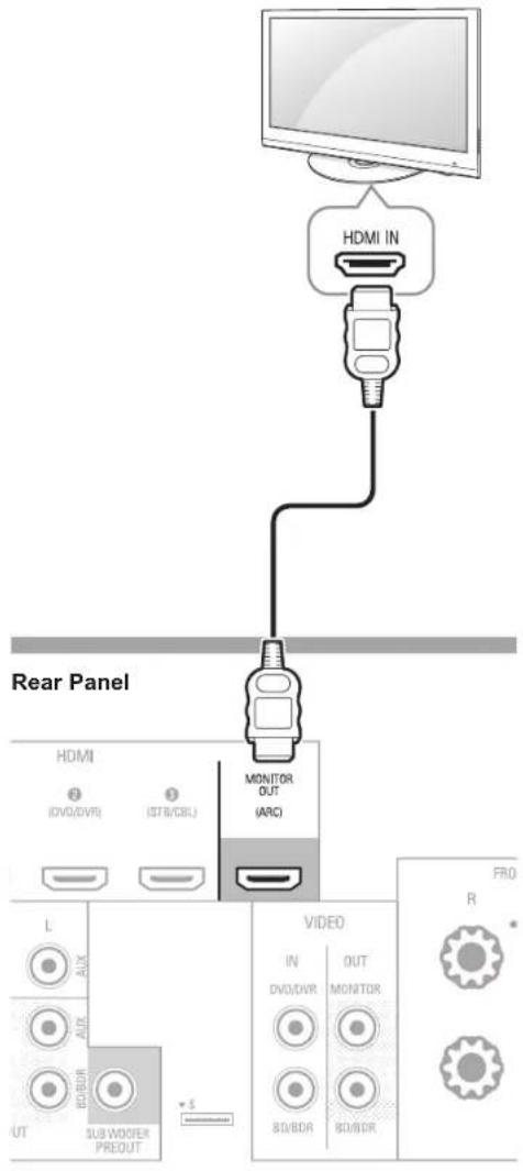
HDMI Monitor Out Connector
If your TV has an HDMI connector and you have HDMI video source devices, use an HDMI cable (not supplied) to connect your TV to the AVR's HDMI Monitor Out connector.
It will provide the best possible picture quality.
text_image
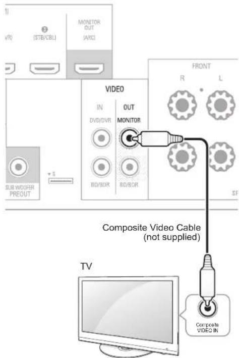
HDMI IN Rear Panel HDMI (DVD/DVR) (STR/CBL) MONITOR OUT (ARC) VIDEO IN DVD/DVR OUT MONITOR 80/8DR 80/8DR PRO R L AUX AUX 80/8DR SUB WOOFER PREDUT SComposite Video Monitor Out Connector
If your TV does not have an HDMI connector, or if your TV does have an HDMI connector but you are connecting some source devices with only composite video connectors, use a composite video cable (not included) to connect the AVR's Composite Monitor Out connector to your TV's composite video connector.
Rear Panel
text_image
11 VR (STB/CBL) MONITOR OUT (ARC) SUB WHOOPER PREOUT VIDEO IN DVD/DVR OUT MONITOR BD/SDR BD/SDR FRONT R L SF Composite Video Cable (not supplied) TV Composite VIDEO IN
Note
- The AVR's on-screen display (OSD) only appears through the Composite Monitor Out connector. If you want to use the AVR's OSD menus you need to connect its Composite Monitor Out connector to your TV even if you are not connecting any composite video source devices to the AVR.
Connect Your Audio and Video Source Devices
Source devices are components where a playback signal originates, e.g., a Blu-ray Disc™ or DVD player; a cable, satellite or HDTV tuner; etc. Your AVR has several different types of input connectors for your audio and video source devices: HDMI, composite video, optical digital audio, coaxial digital audio and analog audio.
Each of your AVR's source buttons is assigned to an analog audio input connector.
The digital inputs are not assigned to any specific sets of analog inputs. Once you select a source device you can use the remote control's DIGITAL button to select the specific audio input connection (HDMI, coaxial digital, optical digital, analog) that you want to listen to. (Note: You cannot select an audio input connection for the FM/AM or USB source buttons.)
As you connect your various source components, fill out the "Source Device Connected" and "Digital Audio Input Connector Used" columns in the following table. it will make it easy to keep track of which devices you have connected to which connectors.
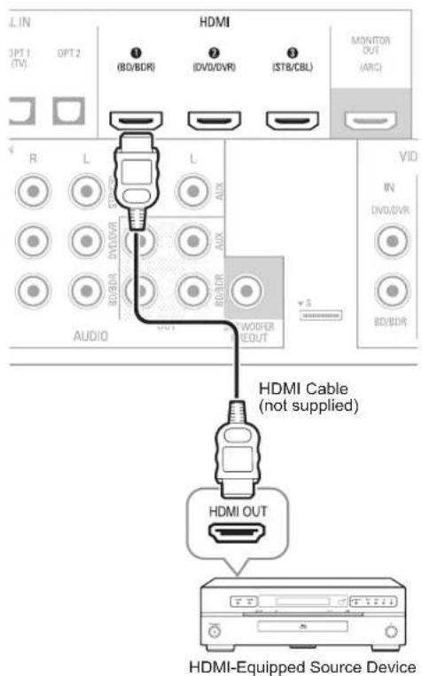
HDMI Devices
If any of your source devices have HDMI connectors, using those connectors will provide the best possible video and audio performance quality. Since the HDMI cable carries both digital video and digital audio signals, you do not have to make any additional audio connections for devices you connect via HDMI cables.
If you have a TV equipped with the HDMI Audio Return Channel function, its sound is fed to the AVR via the HDMI Monitor Out connection's Audio Return Channel, and it will not require additional audio connections to the AVR.
Rear Panel
text_image
L IN OPT 1 (TV) OPT 2 HDMI ① (BD/8DR) ② (DVD/DVR) ③ (STB/CBL) MONITOR OUT (ARC) R L L AUDIO AUX R/R/DWR R/R/DWR R/R/DWR R/R/DWR R/R/DWR R/R/DWR R/R/DWR R/R/DWR R/R/DWR R/R/DWR V ID IN DVD/DVR BD/8DR HDMI Cable (not supplied) HDMI OUT HDMI-Equipped Source DeviceComposite Video Devices
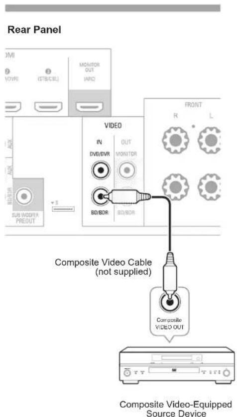
You will need to make composite video connections from your source devices that do not have HDMI video connections. You will also need to make an audio connection from the device to the AVR.
text_image
Rear Panel VOMI (VOVR) (STB/CBL) MONITOR OUT IARC SUB WOODEN PREDUT AVX DVD IN DVII/DVR OUT MONITOR BD/BOB BD/BOB FRONT R L Composite Video Cable (not supplied) Composite VIDEO OUT Composite Video-Equipped Source DeviceOptical Digital Audio Devices
If your source devices have optical digital outputs, connect them to the AVR's optical digital audio connectors.
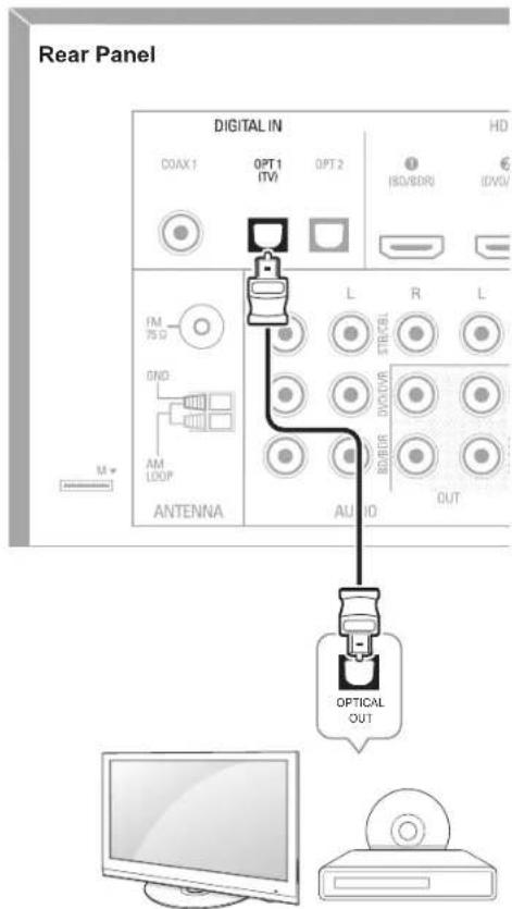
text_image
Rear Panel DIGITAL IN COAX1 OPT 1 (TV) OPT 2 HD ISO/BDRI ISO/DVD/ IM 75 Ω GND AM LOOP ANTENNA L R L AUDIO OUT OPTICAL OUTCoaxial Digital Audio Devices
If your source devices have coaxial digital outputs, connect them to the AVR's coaxial digital audio connectors.
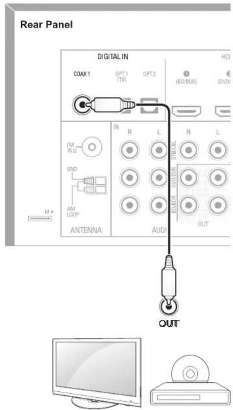
text_image
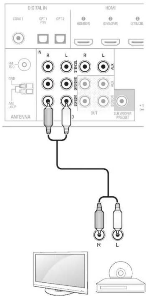
Rear Panel DIGITAL IN COAX1 OPT 1 (TVI) OPT 2 HD (80/80R) IDVV IN R L R L R/DVD AM LOOP ANTENNA AUDI OUT M OUTMake analog audio connections from your source devices that do not have HDMI or digital audio connections. If you're connecting video sources to the AVR's Video 1 or Video 2 audio inputs, you must also connect the source device's composite video output to the corresponding composite video connector.
Rear Panel
text_image
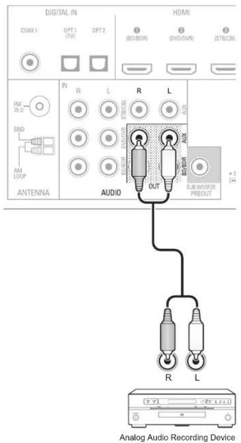
DIGITAL IN HDMI CDAX 1 OPT 1 OPT 2 (BD/BDI) (DVD/DVR) (STB/CBL) FM PS 0 GND AM LOOP ANTENNA IN R L R L STB/CBL DVD/DR ALUX BO/DDR OUT BO/DDR SUN WOOPER PREDUT +3 R LConnect an analog audio recorder's inputs to the AVR's analog audio Tape Out connectors. You can record any analog audio input signal (except Tape In).
Rear Panel
text_image
DIGITAL IN COAX1 OPT 1 OPT 2 BVD/BDRI DVD/DVR JSTR/CBI HDMI FM 75 Ω IN R L R L STD/CBI AUX END AM LOOP ANTENNA AUDIO OUT BDD/RD SUB WOOFER PREOUT Analog Audio Recording DeviceVideo Recorders
Connect an analog video recorder's video input connector to the AVR's Video 1 Out composite video connector and its audio input connectors to the AVR's Video 1 Out analog audio connectors. You can record the Video 2 composite video input signal.
Rear Panel
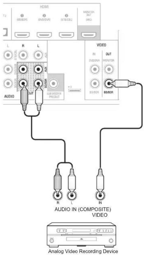
text_image
HDMI T2 (HD/DDR) (IVDM/VR) (STR/CBL) MDI/ON OUT (MCI) L R L AUX SIN/CDL SIN/DDR SIN/DDR AUDIO R OUT B0/DDR SUB VIDEO PRE OUT VIDEO IN DIN/DDR MONITOR B0/DDR B0/DDR R L IN AUDIO IN (COMPOSITE) VIDEO Analog Video Recording DeviceConnect the Tuner Antennas
- Connect the supplied FM antenna to the AVR's FM 75Ω antenna connector. For the best reception, extend the FM antenna as far as possible.
- Bend and fold the base of the supplied AM antenna as shown and connect the antenna wires to the AVR's AM and Gnd connectors. Rotate the antenna as necessary to minimize background noise.
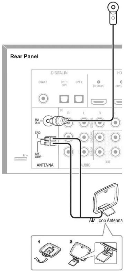
text_image
Rear Panel DIGITAL IN COAX1 OPT 1 OPT 2 IBD/BDMO HD IN R L R L FM 75 Ω GND AM LOOP ANTENNA AUDIO OUT AM Loop Antenna 1 2Connect to AC Power
Connect the AC power cord to the AVR's AC Input connector and then to a working AC power outlet.
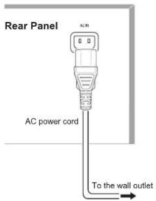
text_image
Rear Panel ACIN 0 0 AC power cord To the wall outlet
Note
- Before connecting the AC power cord, make sure that the AC voltage listed on the AVR's back panel matches the AC voltage used in your country.
Install the Batteries in the Remote Control
Remove the remote control's battery cover, insert the two supplied AAA batteries as shown in the illustration, and replace the battery cover.
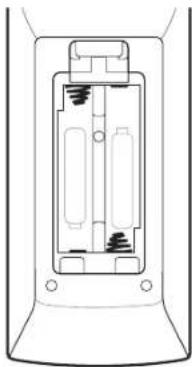
natural_image
Technical line drawing of a mechanical component or housing (no text or symbols)
Note
- Remove the protective plastic from the AVR's front panel to keep it from reducing the remote control's effectiveness.
Setup
Turn On the AVR
1 Set the AVR's Main Power switch to "On". (The Standby indicator will glow red.)
2 Press the front-panel On/Standby button.
Main Power Switch Standby Indicator
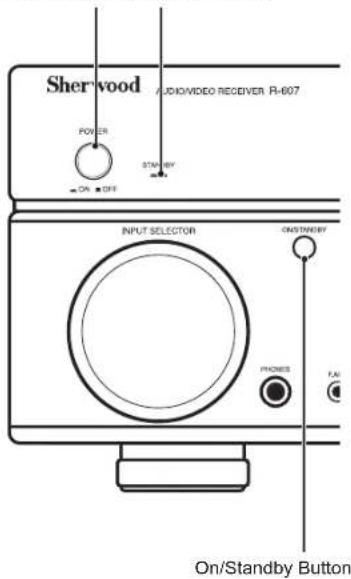
text_image
Sherwood AUDIO/VIDEO RECEIVER R-607 POWER STRAWBY ON STRAWBY INPUT SELECTOR ON STRAWBY PHONES FAI On/Standby ButtonOn the remote control, you can only turn on or off the AVR to standby mode by following the steps below. When the power button is pressed on the main unit, you cannot turn on the main unit even by pressing the power button on the remote control.
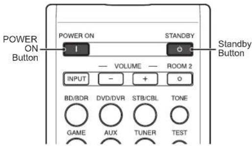
text_image
POWER ON Button POWER ON STANDBY VOLUME ROOM 2 INPUT - + - BD/BDR DVD/DVR STB/CBL TONE GAME AUX TUNER TEST Standby Button1 Press POWER ON on the standby mode.
2 Press STANDBY to turn on the standby mode.
Configure the AVR for Your Speakers
You will be using the following remote control buttons to configure your AVR:
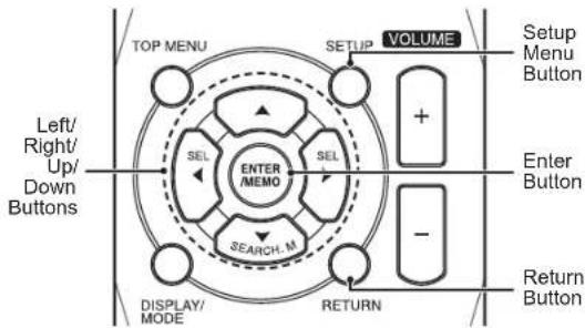
text_image
TOP MENU VOLUME SETUP + Setup Menu Button Enter Button SEL ENTER /MEMO SEL - SEARCH M RETURN DISPLAY/ MODE Return Button Left/ Right/ Up/ Down Buttons1 Turn on your TV and select the TV input where you connected the AVR's Composite Monitor Out connector in Connect Your Audio and Video Source Devices, on page 10.

Note
- Although you can configure the AVR using only its front-panel message display, it is much easier to use the On-Screen Display (OSD) menu system.
2 Press the remote control's SETUP button. The AVR's OSD System Setup menu will appear on the TV.
System Setup
-
Speaker Setup
-
HDMI Setup
- Audio Setting's
- Auto Power Control
- Speakers On/OFF
3 Use the remote's arrow and ENTER buttons to select "Speaker Setup". The Speaker Setup menu will appear.
- Speaker Setup
a. Speaker Settings
b. Crossover
6. Channel Level
6. Speaker Distance
4 Select "Speaker Settings". The Speaker Settings menu will appear.
1a. Speaker Setting'sla.
| Front | < LARGE > |
| Center | [ LARGE ] |
| Surround L/R | [ LARGE ] |
| Subwoofer | [ YES ] |
5 Use the remote's left and right arrow buttons to select NO, SMALL or LARGE for the Front, Center and Surround speaker positions, depending on the speakers you have connected to the receiver.
NO: Select this setting if you have not connected a speaker in that position (not available for the Front speakers).
SMALL: Select this setting if the speaker is not capable of producing clean, deep bass energy at output levels that match those produced by a powered subwoofer. All bass in that channel is removed from that speaker and is sent to the subwoofer (or to the Front speakers if Subwoofer is set to NO). Most speakers (unless they are large and powerful) should be considered SMALL.
LARGE: Select this setting if the speaker is capable of producing clean, deep bass energy at output levels that match those produced by a powered subwoofer. All bass in that channel is sent to that speaker.
When you're finished, press the remote control's RETURN button to return to the Speaker Setting menu.

Note
- If your system has a subwoofer and you set the Front speakers to LARGE, the subwoofer may not output audio except for Dolby Digital and DTS encoded program material that contains LFE channel information. If you set your Front speakers to LARGE and you want your subwoofer to reproduce bass from all program material, set the Subwoofer to PLUS (see below).
- For Subwoofer, select YES (if your system has a subwoofer), NO (if your system does not have a subwoofer), or PLUS (if your system has a subwoofer, you set your Front speakers to LARGE and you want your subwoofer to reproduce bass from all program material).
6 For now you can skip the "Crossover" setting.
7 Select "Speaker Distance". The Speaker Distance menu will appear.
1d. Speaker Distanceid.
| Units | [ FEET ] |
| Front L | < 100ft) |
| Center | [ 10.0ft ] |
| Front R | [ 10.0ft ] |
| Surround R | [ 10.0ft ] |
| Surround L | [ 10.0ft ] |
| Subwoofer | [ 10.0ft ] |

Note
- The unit display may differ depending on the distributed models.
8 Measure the distance from each speaker in your system to the listening position. Write down the distances.
9 Use the remote's left and right arrow buttons to change the distance setting for each speaker so it matches the distance you wrote down in step 8. When you're finished, press the remote control's RETURN button to return to the Speaker Setting menu.
10 Select "Channel Level". The Channel Level menu will appear. Use the remote's left and right arrow buttons to set Test Tone to "Manual" and press the remote's ENTER button. After the on-screen countdown you will hear test noise through the front left speaker.
- Channel Level 10
Test Tone < Material >
11 Sit in the main listening position and adjust the AVR's volume control so the test noise is moderately loud. Note the volume of the test noise through the first speaker. Press the remote's down arrow button to advance the test noise to each of your system's speakers and note the volume level of the noise in each speaker.
12 As you advance the test noise through the speakers, use the remote's left and right arrow buttons to adjust the volumes of the channels until all of them play at the same volume. When you're finished, press the remote's SETUP button to turn of the on-screen menus.
Operation
Operating Your AVR
Now that you have installed your components and completed a basic configuration, you are ready to begin enjoying your home theater system.
Controlling the Volume
Adjust the volume either by turning the front-panel Volume knob (clockwise to increase volume or counterclockwise to decrease volume) or by pressing the Volume Up/Down buttons on the remote.
Muting the Sound
To mute all speakers and the headphones, press the Mute button on the remote. Any recording in progress will not be affected. The MUTE message will appear in the front-panel display as a reminder. To restore the sound, press the Mute button again, or adjust the volume.
Listening Through Headphones
Plug the 1/4-inch stereo plug on a pair of headphones into the front-panel Phones jack for private listening.

Note
- For information about turning off the speakers during headphone listening, see page 15.
Selecting a Source
There are two different ways to select a source:
- Rotate the front-panel INPUT SELECTOR.
- Directly select any source by pressing its Source Selector button on the remote.
The AVR selects the analog audio and video inputs assigned to the source and any other settings you made during setup.
The digital audio inputs are not assigned to any specific sets of analog inputs. Once you select a source device you can use the remote control's Audio Input Select (DIGITAL) button to select the specific audio input connection (HDMI, coaxial digital, optical digital, analog) that you want to listen to. (Note: You cannot select an audio input connection for the FM/AM or USB source buttons.)
The source name, the selected audio input and the surround mode will appear on the front panel.
Video Troubleshooting Tips
If there is no picture:
- Check the source selection.
- Check all connections for a loose or incorrect connection.
- Check the video-input selection on the TV/display device.
Additional Tips for Troubleshooting HDMI Connections
- Turn off all devices (including the TV, the AVR and any source components).
- Unplug the HDMI cables, starting with the cable between the AVR and the TV, and continuing with the cables between the AVR and each source device.
- Carefully reconnect the cables from the source devices to the AVR. Connect the cable from the AVR to the TV last.
- Turn on the devices in this order: TV, AVR, source devices.

Note
- Depending upon the particular components involved, the complexity of the required communication between HDMI components may cause delays of up to a minute in the completion of some actions, such as input switching or switching between SD and HD channels.
Listening to FM and AM Radio
Select the AM/FM source. Use the Tuning Up/Down buttons to tune a station, which will be shown on the front-panel display. For automatic tuning, press and hold the Tuning Up/Down buttons to scan stations until a station with acceptable signal strength is found. For manual tuning, press each Tuning button until the desired station is found. Using the FM Mono mode may improve the reception of weaker stations.
Preset Stations
A total of 30 stations (AM and FM combined) may be stored as presets. When the desired station has been tuned in, press the Memory button and the preset number will flash on the front-panel Message display. Use the remote's Number buttons to enter the desired preset number.
To tune a preset station, press the Preset Up/Down buttons or enter the preset number using the remote's Number buttons.
RDS
RDS(Radio Data System) is a method for sending information signals together with the transmitter signals. These codes contain Program Service name (PS), A list of Program Types (PTY), Radio Text (RT).

Note
- RDS is available only in models that are distributed in Europe.
• RDS is only possible in the FM band. - RDS searches for the preset stations only. If no stations have been stored in the memory, or if the program type could not be found among the preset stations, "NO PTY" is displayed.
Listening to Media on a USB Device
Your AVR is compatible with USB 2.0 or USB 1.1 media in the FAT 16 or FAT 32 file format and is compatible with the following MP3 and WMA media:
- MP3: Bit rates between 96 – 320kbps. Fixed bit-rates at 44.1kHz sampling is recommended. Variable bit-rates (VBR) are playable, but playing time may be displayed incorrectly. Files must have a “.mp3” file extension.
- WMA: Bit rates of 64kbps or higher. NOTE: Bit rates of 80kbps and 256kbps are not compatible. Files must have a ".wma" file extension.
A maximum number of 65,536 folders and files can be supported.
Playing files on a USB device
1 Insert the USB drive into the AVR's front-panel USB port.

Caution
- Do not connect a personal computer or peripheral to the USB port. USB hubs are not supported.
2 Select USB as the source device. "USB" will appear on the front-panel display, and after the AVR loads the contents of the current folder the USB playback screen will appear on the OSD.
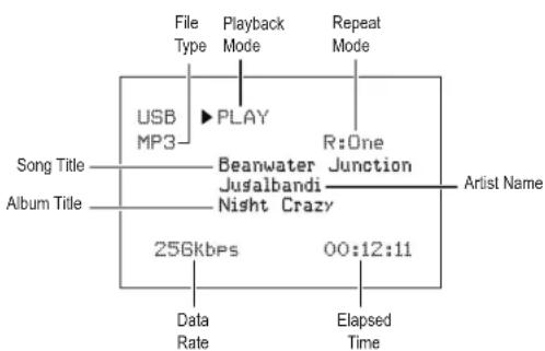
flowchart
graph TD
    A["File Type"] --> B["USB MP3"]
    B --> C["PLAY"]
    C --> D["Beanwater Jusalbandi Night Crazy"]
    D --> E["R:One Junction"]
    E --> F["Artist Name"]
    G["Album Title"] --> H["256Kbps"]
    H --> I["Data Rate"]
    H --> J["00:12:11"]
    K["Playback Mode"] --> L["Repeat Mode"]
Use the remote's Transport Control buttons to control playback.
To browse the contents of the current folder, press the remote's RETURN button. The USB folder screen will appear on the OSD for 20 seconds.
USB
▲Last
002/010
[Ants Ate My Silkworms.mp3]
[Night Crazy.mp3]
[Beanwater Junction, Part 1]
[Yarmishun Jim.mp3]
[Successfully Assimilated, P]
[The Lost Transit Center.mp]
[Successfully Assimilated, P]
[Beanwater Junction, Part 2]
ENTER
▼ Next
Use the remote's UP/Down and ENTER buttons to highlight and select tracks.

Caution
- To prevent damage or malfunction, press the remote's Stop (■) Transport Control button before removing the USB device from the AVR's USB port.
Selecting a Surround Mode
Selecting a surround mode can be as simple or sophisticated as your individual system and tastes. Feel free to experiment, and you may find a few favorites for certain sources or program types. You can find more detailed information on surround modes in Audio Processing and Surround Sound, below.
To select a surround mode, press the Surround Mode Select buttons. Each press advances to the next available surround mode.
Digital surround-sound modes, such as Dolby Digital and DTS systems, are available only with specially encoded programs, such as those available via HDTV, DVD and Blu-ray Disc media and digital cable or satellite television. Other surround modes such as Dolby Pro Logic II may be used with digital or analog signals to create a different surround presentation or to use a different number of speakers.
Surround mode selection depends upon the number of speakers in your system, the programs you are watching or listening to, and your personal tastes.
Advanced Functions
Much of the adjusting and configuration your AVR requires is handled automatically, with little intervention required on your part. You can also customize your AVR to suit your system and your tastes. In this section, we will describe some of the more advanced adjustments available to you.
Audio Processing and Surround Sound
Audio signals can be encoded in a variety of formats that affect not only the quality of the sound but also the number of speaker channels and the surround mode. You may also manually select a different surround mode, when available.
Analog Audio Signals
Analog audio signals usually consist of two channels – left and right. Your AVR offers several options for analog playback:
- Stereo: When you want conventional 2-channel playback, press the STEREO button. Sound will be output from the front left and right speakers.
- 5-Ch Stereo: When you want to hear stereo sound through all of the system's speakers (such as during a party), select 5CH STEREO via the Surround Mode Select buttons. This plays the left-channel signal through the front left and surround left speakers, the right-channel signal through the front right and surround right speakers, and a summed mono signal through the center speaker.
- Analog Surround Modes: Your AVR is able to process 2-channel audio signals to produce multi-channel surround sound, even when no surround sound has been encoded in the recording. Among the available modes are Dolby Pro Logic II, Dolby Pro Logic, DTS Neo: 6, Theater, Hall, Stadium, Club and Arena modes. Use the Surround Mode Select buttons to select one of these modes.
Digital Audio Signals
Digital audio signals offer greater flexibility and capacity than analog signals and allow the encoding of up to 5.1 channels of discrete channel information directly into the signal. The result is improved sound quality and startling directionality, since each channel's information is transmitted independently of the other channels. High-resolution recordings sound extraordinarily distortion-free, especially in the high frequencies.
Digital surround-sound formats include Dolby Digital 2.0 (two channels only), Dolby Digital 5.1, Dolby Digital EX, Dolby Digital Plus, Dolby TrueHD, DTS-HD High-Resolution Audio, DTS-HD, DTS 5.1, DTS 96/24, 2-channel PCM modes in 44.1kHz, 48kHz, 88.1kHz, 96kHz or 176.4kHz, and 5.1 or 7.1 multichannel PCM. (Your AVR will downmix the discrete surround back-
channel information in 6.1-channel and 7.1-channel recordings into your system's surround left and surround right channels.)
Surround Mode Selection
Surround-mode selection depends upon the format of the incoming audio signal as well as your personal taste. Although there is never a time when all of the AVR's surround modes are available, the table below indicates which surround modes are available for a given input.
| Input Signal Format | Available Surround Modes |
| Dolby TrueHD(Only for R- 607),Dolby Digital Plus (Only for R- 607),Dolby Digital(7.1-channel/5.1-channel) | Corresponding Dolby TrueHD(Only for R-607) or Dolby Digital mode (Theater, Hall, Stadium, Club, Arena and 5-Ch Stereo are also available for 5.1-channel programs) |
| Dolby Digital(2.0-channel) | Dolby Pro Logic II Movie, Dolby Pro Logic II Music, Dolby Pro Logic II Game, Dolby Pro Logic |
| DTS-HD (Only for R- 607),DTS, DTS 96/24 | Corresponding DTS Mode(Theater, Hall, Stadium, Club, Arena and 5-Ch Stereo are also available for 5.1-channel programs) |
| PCM(2-channel),Analog(2-channel) | Dolby Pro Logic II Movie, Dolby Pro Logic II Music, Dolby Pro Logic II Game, Dolby Pro Logic, DTS Neo:6 Cinema, DTS Neo:6 Music, Theater, Hall, Stadium, Club, Arena, 5-Ch Stereo |
| MP3/WMA | Dolby Pro Logic II Movie, Dolby Pro Logic II Music, Dolby Pro Logic II Game, Dolby Pro Logic, DTS Neo:6 Cinema, DTS Neo:6 Music, Theater, Hall, Stadium, Club, Arena, 5-Ch Stereo |
When in doubt, check the broadcast or the jacket of your disc for more information on which surround modes are available. Usually, nonessential sections of a disc, such as trailers, extra materials or the disc menu, are available only in Dolby Digital 2.0 (2-channel) or PCM 2-channel mode. Look for an audio setup section in the disc's menu.
Also, make sure your disc player's audio output is set to the original bitstream rather than 2-channel PCM. Stop play and check the player's output setting.
Adjusting the Channel Volumes
In addition to using the AVR's built-in test noise to configure the AVR for your speakers as explained in Configure the AVR for Your Speakers, you can also adjust the volume of any channel at any time to compensate for individual program sources or your personal taste.
1 Press the remote's Channel Level button. The Message Display will show the left channel volume level.
2 Use the remote's up and down arrow buttons to display the channel you want to adjust.
3 Use the remote's left and right arrow buttons to adjust the channel's volume.
Press the RETURN button when you're finished.
Recording
Two-channel analog audio signals, as well as composite video signals, are normally available at the appropriate recording output connectors. To make a recording, connect your audio or video recorder to the appropriate AVR output connectors as described in the Making Connections section, insert blank media in the recorder and make sure the recorder is turned on and recording while the source is playing. Refer to the recording device's instructions for complete information about making recordings.

Note
- The AVR does not convert digital signals to analog. Only devices connected to the analog audio and composite video input connections can be recorded.
- HDMI video sources are not available for recording.
- Please make certain that you are aware of any copyright restrictions on any material you record. Unauthorized duplication of copyrighted materials is prohibited by law.
Sleep Timer
The sleep timer sets the AVR to play for up to 90 minutes and then turn off automatically. Press the Sleep button on the remote, and the time until turn-off will be displayed on the front-panel Message display The available settings are 30 min., 60 min., 90 min. and OFF.
When the sleep timer has been set, a small crescent-moon icon will appear on the front-panel display.
If you press the SLEEP button after the timer has been set, the remaining play time will be displayed. Press the SLEEP button again to change the play time.
Processor Reset
If the AVR behaves erratically after a power surge, first turn off the front-panel Main Power switch and unplug the AC power cord for at least 3 minutes. Plug the cord back in and turn the AVR on. If this procedure doesn't help, reset the AVR's processor as described below.

Note
- Resetting the processor will erase all user configurations, including speaker and level settings, and tuner presets. After a reset, reenter all of these settings from your notes in the Appendix worksheets.
To reset the AVR's processor:
1 Press the front-panel Standby/On switch to place the unit in the Standby mode (the Standby Indicator LED will turn red).
2 Press and hold the SURROUND down button on the remote control as pressing and holding the front-panel Standby/On switch simultaneously.
3 When the RESET message "RESET?" appears on the front-panel Message display, press BAND.
4 When the RESET message "OK?" appears on the front-panel Message display, press BAND.
Memory
If the AVR is unplugged or experiences a power outage, it will retain your user settings for up to two weeks.
Troubleshooting
If you experience any of the following difficulties while using the system, use this troubleshooting guide to help remedy the problem before requesting servicing. Should any problem persist, consult your nearest authorized dealer or authorized independent company.
If the unit does not operate normally due to external influence such as static electricity, disconnect the power plug from the outlet and insert again to return to normal operating conditions.
| Symptom Cause Solution | ||
| Unit does not function when Main Power switch is turned on. | No AC power. | Ensure that the power cord is plugged into a live AC power outlet.Check if the AC outlet is switch-controlled. |
| Front-panel Message display lights, but there's no sound or picture. | Intermittent input connection.Mute is on.Volume control is turned down. | Secure all input and speaker connectionsPress Mute button.Turn up Volume control. |
| No sound from any speaker. | Speakers set to “Off” in System Setup menu. | Set speakers to “On” in System Setup menu. See page 15, for more information. |
| No sound from any speaker; PROTECT message appears on Message display. | Amplifier is in protection mode due to possible short circuit.Amplifier is in protection mode due to internal problems. | Check all speaker wires at speaker and AVR connections for crossed wires.Contact your local service center. |
| No sound from center or surround speakers. | Incorrect surround mode.Program material is monophonic.Incorrect speaker configuration.Program material is stereo. | Select a surround mode other than stereo.Mono programs contain no surround information.Check the speaker configuration in the setup menu.The surround decoder may not create center- or surround-channel information from non-encoded stereo programs. |
| Unit does not respond to remote control commands. | Weak batteries in remote.AVR not selected.Remote sensor is obscured. | Change batteries in remote.Press the Setup/AVR button.Ensure that the AVR’s front-panel remote sensor is in the line of sight of the remote. |
| Intermittent buzzing in tuner. | Local interference. | Move the AVR or antenna away from computers, fluorescent lights, motors or other electrical appliances. |
Specifications
| Audio Section | |
| Power Output | 100 W x 5ch (20 Hz~20 kHz, 6 Ohms, THD 1 %/Only Channel Driven)75 W x 2ch (20 Hz~20 kHz, 6 Ohms, THD 0.1 %/Stereo Mode) |
| Input sensitivity/impedance 200 mV/47k ohms | |
| Signal-to-noise ratio (IHF-A) 95 dB | |
| Surround system adjacent-channel separation | Dolby Pro Logic/PLII: 40 dBDolby Digital: 55 dBDTS: 55 dB |
| Frequency response 10Hz - 100kHz: ±3 dB | |
| High instantaneous-current capability (HCC) ±25 amps | |
| FM Tuner Section | |
| Frequency range 87.5 - 108.0 MHz | |
| Usable sensitivity IHF 1.3 μV/13.2 dBf | |
| Signal-to-noise ratio (mono/stereo) 65 dB/62 dB | |
| Distortion (mono/stereo) 0.2 %/0.3 % | |
| Stereo separation 35 dB @ 1 kHz | |
| Image rejection 80 dB | |
| IF rejection 80 dB | |
| AM Tuner Section | |
| Frequency range 520 - 1720 kHz, 522 -1161 kHz | |
| Signal-to-noise ratio 45 dB | |
| Usable sensitivity (loop) 500 μV | |
| Selectivity (±10kHz) 30 dB | |
| IF rejection 80 dB | |
| Video Section | |
| Television format | NTSC/PAL |
| Input level/impedance | 1 Vp-p/75 ohms |
| Output level/impedance | 1 Vp-p/75 ohms |
| Video frequency response (composite video) | 10 Hz - 8 MHz (-3 dB) |
| HDMI | With 3 D and Deep Color |
| General Specifications | |
| Power requirement | AC 120 V/60 Hz, AC 230 V/50 Hz |
| Power consumption | <0.5 W (standby), 280 W maximum |
| Dimensions (W×H×D, including protruding parts) | 17.1" x 5.4" x 14.9" (435mm x 138mm x 379mm) |
| Weight (Net) | 17.6lb (8kg) |
MEMO
R&TTE Directive 1999/5/EC
ATTENTION
AFIN DE REDUIRE LES RISQUE DE CHOC ELECTRIQUE, N'ENLEVEZ PAS LE PANNEAU ARRIERE. AUCUNE PIÈCE À L'INTÉRIEUR NE PEUT ÊTRE RÉPARÉE PAR L'UTILISATEUR. EN CAS DE PROBLÈME, S'ADRESSER À DU PERSONNEL TECHNIQUE QUALIFIÉ.

text_image
1 2 3 4 5 6 7 8 OUTPUT IN HDMI MOUNT AVIO R L R L R L R L R L R L R L R L R L R L R L R L R L R L R L R L R L R L R L R L R L R L R L R L R L R R R R R R R R R R R R R R R R R R R R R R R R R R R R R R R R R R R R R R R R R R R R R R R R R Rtext_image
TV C FL 30° 30° FR 110° 110° SL SR SUBtext_image
DIGITAL IN HDMI CDAX 1 OPT 1 OPT 2 (TV) (BD/BD/P) (DVD/DVD) (ISTB/CBL) FM 75 Ω DND AM LOOP ANTENNA IN R L R L STB/CBL DV/DWR BDO/R AUX OUT SUB WOOFER PRED OUT R Ltext_image
DIGITAL IN COAX1 OPT 1 OPT 2 I/O/BOB DVD/DVR ISTB/CBL IN R L R L 75 Ω GND AM LOOP ANTENNA AUDIO OUT R L AUX BOB/BOB SUB WOOFER PREFOUTnatural_image
Technical line drawing of a mechanical component or housing (no text or symbols)
Remarque
-
Speaker Setup
-
HDMI Setup
- Audio Setting's
- Auto Power Control
- Speakers On/Off
| Front | < LARGE > |
| Center | [ LARGE ] |
| Surround L/R | [ LARGE ] |
| Subwoofer | [ YES ] |
1d. Speaker DistanceId.
| Units | [ FEET ] |
| Front L | < 10.0ft] |
| Center | [ 10.0ft ] |
| Front R | [ 10.0ft ] |
| Surround R | [ 10.0ft ] |
| Surround L | [ 10.0ft ] |
| Subwoofer | [ 10.0ft ] |

Remarque
1c. Channel Level 10.
Test Tore < [F100]
[Ants Ate My Silkworms.mp3]
[Night Crazy.mp3]
[Beanwater Junction, Part 1]
[Yarmishun Jim.mp3]
[Successfully Assimilated, P]
[The Lost Transit Center.mp]
[Successfully Assimilated, P]
[Beanwater Junction, Part 2]
ENTER ▼ Next
R&TTE Directive 1999/5/EC

text_image
1 2 3 4 5 6 7 8 OUTPUT IN HDMI MOUNT AVIO AUDIO VIDEO R L R L R L R L R L R L R L R L R L R L R L R L R L R L R L R L R L R L R L R L R L R L R L R L R L R L R L R L R L R L R L R L R L R L R L R MOUNT Speaker Reference Source AC R1 Conectores de audio digital
2 Conectores HDMI
3 Conectores de la antena de radio
4 Conectores de audio analógico
5 Conector del Subwoofer
text_image
TV C FL 30° 30° FR 110° 110° SL SR SUBtext_image
Panel Trasero DIGITAL IN COAX 1 OPT 1 (TV) OPT 2 HD (ISO/8DR) ( DVD/ FM 75 G GND AM LOOP ANTENNA L R L ST6/DR DV8/WR SENSOR OUT AUDIO OPTICAL OUTTV, Reproductor DVD, etc.
Dispositivos de Audio Digital Coaxial
text_image
Panel Trasero DIGITAL IN COAX1 OPT 1 (TV) OPT 2 HD (RG/8DR) (DVD) IN R L R L S10/DL AM LOOP ANTENNA AUDI OUT M SALUTATV, Reproductor DVD, etc.
text_image
DIGITAL IN HDMI CDAX 1 OPT 1 OPT 2 (TV) (BD/BD/P) (DVD/DVD) (ISTB/CBL) FM 75 Ω DND AM LOOP ANTENNA IN R L R L STB/CBL DV/DVR BDO/R AUX OUT R D/D/WM SUB WOOFER PRED OUT R LTV, Reproductor DVD, etc.
Grabador de audio
natural_image
Technical line drawing of a mechanical component with internal slots and mounting holes (no text or symbols)
Nota
-
Speaker Setup
-
HDMI Setup
- Audio Setting's
- Auto Power Control
- Speakers On/OFF
| Front | < LARGE > |
| Center | [ LARGE ] |
| Surround L/R | [ LARGE ] |
| Subwoofer | [ YES ] |
| Units | [ FEET ] |
| Front L | < 10.0ft) |
| Center | [ 10.0ft ] |
| Front R | [ 10.0ft ] |
| Surround R | [ 10.0ft ] |
| Surround L | [ 10.0ft ] |
| Subwoofer | [ 10.0ft ] |

Nota
1c. Channel Level 10.
Test TGF6 < [F100000] >