Ice Cube2 - Basket ROBLIN - Free user manual and instructions
Find the device manual for free Ice Cube2 ROBLIN in PDF.

User questions about Ice Cube2 ROBLIN
0 question about this device. Answer the ones you know or ask your own.
Ask a new question about this device
Download the instructions for your Basket in PDF format for free! Find your manual Ice Cube2 - ROBLIN and take your electronic device back in hand. On this page are published all the documents necessary for the use of your device. Ice Cube2 by ROBLIN.
USER MANUAL Ice Cube2 ROBLIN
natural_image
Technical line drawing of a mechanical assembly with a square top and rectangular base (no text or symbols)Libretto di Istruzioni Instructions Manual Manuel d'Instructions Bedienungsanleitung Gebruiksaanwijzing
INDICE
IT
CONSIGLI E SUGGERIMENTI ....3
CARATTERISTICHE 4
INSTALLAZIONE 6
USO 11
MANUTENZIONE 12
INDEX
EN
RECOMMENDATIONS AND SUGGESTIONS....16
CHARACTERISTICS....17
INSTALLATION 19
USE....24
MAINTENANCE....25
SOMMAIRE
FR
CONSEILS ET SUGGESTIONS 29
CARACTERISTIQUES ....30
INSTALLATION 32
UTILISATION....37
ENTRETIEN....38
INHALTSVERZEICHNIS
DE
natural_image
Illustration of a kitchen induction setup with a lamp emitting green smoke, no text or symbols present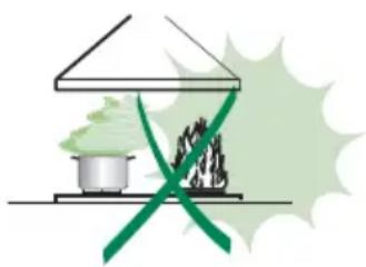
natural_image
Illustration of a greenhouse with a pot and smokestack emitting vapor, crossed by green lines (no text or symbols)Componenti
text_image
Exploded view diagram of a mechanical device with numbered parts and labeled components
text_image
347 MIN 780 - MAX 1030 MIN 860 - MAX 1140 650 100 598 **
natural_image
Technical drawing of a square frame with a central circular hole and dimension label (483), no readable text or symbols beyond the dimension line.
text_image
21.5 85 76.3 287.5 135 76.3 750 Min. 650mm Min. 650mmnatural_image
Technical diagram of a mechanical assembly with a base and mounting bracket, showing alignment lines (no text or symbols)natural_image
Technical illustration of a screwdriver inserted into a mechanical assembly (no text or symbols)
text_image
Technical diagram of a mechanical assembly with labeled components and directional arrows indicating motion or force directions.Connessioni
USCITA ARIA VERSIONE ASPIRANTE
natural_image
Technical line drawing of a mechanical assembly with mounting base and internal components (no text or symbols)
text_image
24 EFGHABCDQuadro comandi
natural_image
Illustration of two electronic devices with green leads, one emitting a probe (no text or symbols)natural_image
Diagram showing a container with a rotating arrow and a close-up of its interior (no text or symbols)natural_image
Hand holding a smartphone with a green directional arrow on screen (no text or symbols)natural_image
Illustration of a hand pressing down on a green surface with a green arrow indicating direction (no text or symbols)Illuminazione
natural_image
Illustration of a hand holding a small object with a green flag above it (no text or symbols)Illuminazione
natural_image
Technical line drawing of a mechanical device with no visible text or symbolsThe Instructions for Use apply to several versions of this appliance. Accordingly, you may find descriptions of individual features that do not apply to your specific appliance.
INSTALLATION
- The manufacturer will not be held liable for any damages resulting from incorrect or improper installation.
- The minimum safety distance between the cooker top and the extractor hood is 650 mm (some models can be installed at a lower height, please refer to the paragraphs on working dimensions and installation).
- Check that the mains voltage corresponds to that indicated on the rating plate fixed to the inside of the hood.
- For Class I appliances, check that the domestic power supply guarantees adequate earthing.
Connect the extractor to the exhaust flue through a pipe of minimum diameter 120 mm. The route of the flue must be as short as possible.
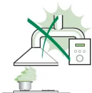
- Do not connect the extractor hood to exhaust ducts carrying combustion fumes (boilers, fireplaces, etc.).
- If the extractor is used in conjunction with non-electrical appliances (e.g. gas burning appliances), a sufficient degree of aeration must be guaranteed in the room in order to prevent the backflow of exhaust gas. The kitchen must have an opening communicating directly with the open air in order to guarantee the entry of clean air.
USE
- The extractor hood has been designed exclusively for domestic use to eliminate kitchen smells.
- Never use the hood for purposes other than for which it has been designed.
- Never leave high naked flames under the hood when it is in operation.
- Adjust the flame intensity to direct it onto the bottom of the pan only, making sure that it does not engulf the sides.
- Deep fat fryers must be continuously monitored during use: overheated oil can burst into flames.
- Do not flambè under the range hood; risk of fire
- This appliance is not intended for use by persons (including children) with reduced physical, sensory or mental capabilities, or lack of experience and knowledge, unless they have been given supervision or instruction concerning use of the appliance by a person responsible for their safety.
- Children should be supervised to ensure that they do not play with the appliance.
MAINTENANCE
- Switch off or unplug the appliance from the mains supply before carrying out any maintenance work.
- Clean and/or replace the Filters after the specified time period (Fire hazard).
- Clean the hood using a damp cloth and a neutral liquid detergent.
The symbol 📄 on the product or on its packaging indicates that this product may not be treated as household waste. Instead it shall be handed over to the applicable collection point for the recycling of electrical and electronic equipment. By ensuring this product is disposed of correctly, you will help prevent potential negative consequences for the environment and human health, which could otherwise be caused by inappropriate waste handling of this product. For more detailed information about recycling of this product, please contact your local city office, your household waste disposal service or the shop where you purchased the product.
natural_image
Illustration of a kitchen induction setup with a smokestack emitting vapor and a green X-shaped warning symbol (no text or symbols present)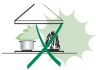
natural_image
Illustration of a greenhouse with a pot and smokestack emitting green smoke, crossed by a green ribbon (no text or symbols)Components
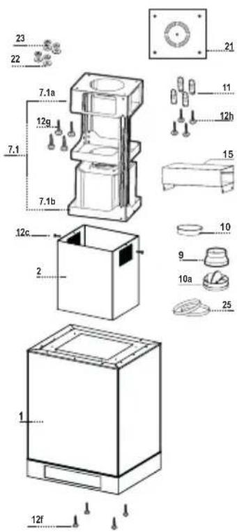
| Ref. | Q.ty | Product | Components |
| 1 | 1 | Hood Canopy complete with: Controls, Light, Filters | |
| 2 | 1 | Telescopic chimney, made up of: | |
| 2.1 | 1 | Upper | chimney |
| 2.2 | 1 | Lower | chimney |
| 7.1 | 1 | Telescopic frame complete with Suction fan, made up of: | |
| 7.1a | 1 | Upper | frame |
| 7.1b | 1 | Lower | frame |
| 9 | 1 | Reduction flange ø 150-120 mm | |
| 10 | 1 | Flangeø | 150 |
| 10a | 1 | Damper ø 150 | |
| 11 | 2 | Side Glass | |
| 12 | 2 | Front Glass | |
| 13 | 4 | Glass Fastener Element | |
| 15 | 1 | Air Outlet Connector | |
| 25 | 2 | Pipe | clamps |
| Ref. | Q.ty | Installation | Components |
| 7.1.1 | 2 | Side Glass Brackets | |
| 7.1.2 | 2 | Centre Glass Brackets | |
| 11 | 4 | Wall plugs ø 10 | |
| 12c | 2 | Screws 2.9 x 6.5 | |
| 12f | 4 | Screws M6 x 10 | |
| 12g | 4 | Screws M6 x 80 | |
| 12h | 4 | Screws 5.2 x 70 | |
| 12p | 10 | Screws M4x10 | |
| 21 | 1 | Drilling template | |
| 22 | 4 | Washers ø 6.4 | |
| 23 | 4 | Nuts M6 |
| Q.ty | Documentation |
| 1 | Instruction Manual |
text_image
Technical diagram of a device with numbered parts and exploded view, including labeled components like 7.1a, 7.1b, and 12f.
text_image
347 MIN 780 - MAX 1030 MIN 860 - MAX 1140 650 100 598 **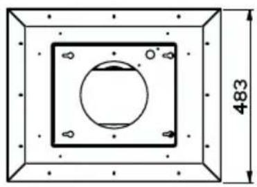
natural_image
Technical drawing of a square frame with a central circular hole and dimension label (483), no readable text or symbols beyond the dimension line.
text_image
21.5 85 76.3 287.5 135 76.3 750 Min. 650mm Min. 650mm* Dimensions of the hood in ducting version.
** Dimensions of the hood in recycling version.

natural_image
Technical diagram of a mechanical assembly with a base and mounting bracket, showing alignment lines (no text or symbols)Drilling the Ceiling/shelf and fixing the frame
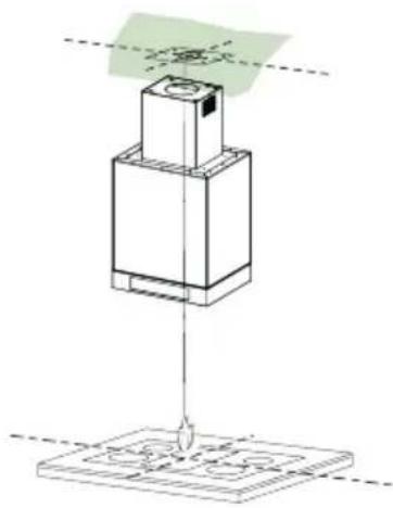
DRILLING THE CEILING/SHELF
- Use a plumb line to mark the centre of the hob on the ceiling/support shelf.
- Place the drilling template 21 provided on the ceiling/support shelf, making sure that the template is in the correct position by lining up the axes of the template with those of the hob.
• Mark the centres of the holes in the template. -
Drill the holes at the points marked:
-
For concrete ceilings, drill for plugs appropriate to the screw size.
- For hollow brick ceilings with wall thickness of 20 mm: drill 10 mm(immediately insert the Dowels 11 supplied).
- For wooden beam ceilings, drill according to the wood screws used.
- For wooden shelf, drill 7 mm.
- For the power supply cable feed, drill 10 mm.
- For the air outlet (Ducted Version), drill according to the diameter of the external air exhaust duct connection.
- Insert two screws of the following type, crossing them and leaving 4-5 mm from the ceiling:
- For concrete ceilings, use the appropriate plugs for the screw size (not provided).
- for Cavity ceiling with inner space, with wall thickness of approx. 20 mm, Screws 12h, supplied.
- For wooden beam ceilings, use 4 wood screws (not provided).
- For wooden shelf, use 4 screws 12g with washers 22 and nuts 23, provided.
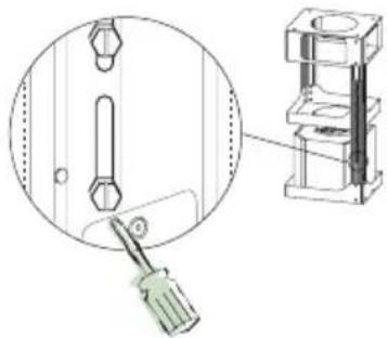
Should it be necessary to adjust the height of the frame, proceed as follows:
- Unfasten the two screws fixing the upper chimney, and remove it from the frame (from the upper part).
- Unfasten the eight metric screws joining the two columns, at the sides of the frame;
- Adjust the frame to the height required, then replace the eight screws removed as described above;
- Insert the upper chimney from above and leave it free on the frame;
- Lift the frame, insert the slots onto the screws and slide them until they lock;
- Tighten the two screws and insert the other two screws provided.
Before final locking of the screws it is possible to make small adjustments to the frame, making sure that the screws do not come out of the adjustment slot.
- The Frame must be securely fastened both due to the weight of the Hood and the stress caused by occasional sideways pressure on the Appliance when in position. When fastened, check that the base is stable even when the Frame is subjected to bending.
- In all cases where the Ceiling is not sufficiently strong at the point of suspension, the Installation technician must strengthen it with suitable plates and counterplates, anchored to structurally sound elements.
natural_image
Technical illustration of a screwdriver inserted into a mechanical assembly (no text or symbols)
text_image
Technical diagram of a mechanical assembly with numbered components and directional arrows indicating motion or force directions.Connections
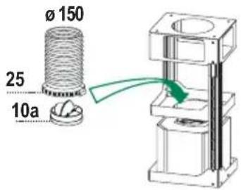
DUCTED VERSION AIR EXHAUST SYSTEM
When installing the ducted version, connect the hood to the chimney using either a flexible or rigid pipe the choice of which is left to the installer.
To install a ø 150
• To install the dumper 10a ø 150.
• Fix the pipe using the pipe clamps 25 provided.
To install a ø 120
- To install a 120 mm air exhaust connection, insert the reducer flange 9 on the dumper 10a.
• Fix the pipe using the pipe clamps 25 provided. - Remove any activated charcoal filters.
text_image
Ø 150 25 10a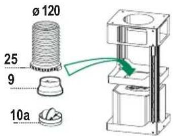
text_image
Ø 120 25 9 10aRecirculation version air outlet
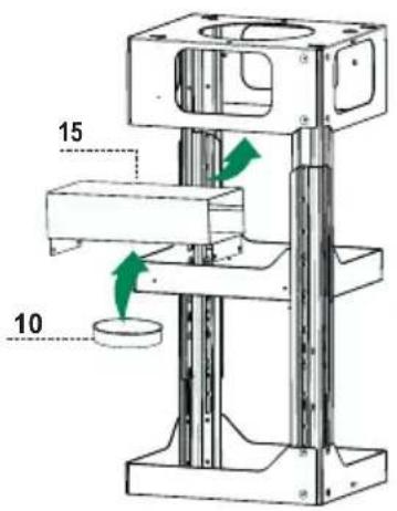
- Fix the connection 15 to the frame using the 4 screws provided.
• Fix the flange 10 to the lower opening of the connection 15. - Connect the hood air outlet to the flange in the lower part of the junction using a rigid or flexible 150 tube (by installer's choice).
text_image
15 10Fitting the Chimney and Fixing the Hood Canopy
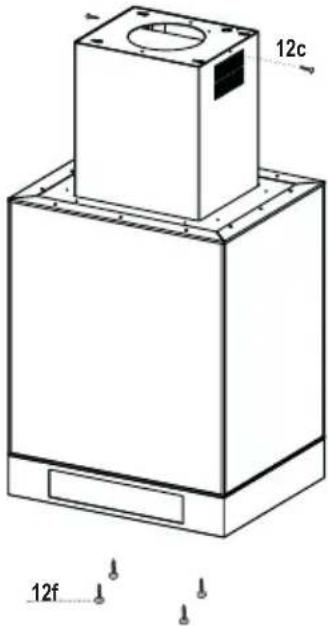
- Insert the Upper chimney with the slots facing upwards if the hood is to be installed in the recirculation version, or vice versa with the slots facing downwards if it is to be installed in the ducting version, and fix the top part to the Upper Chimney Connector using the Screws 12c (2.9 x 9.5) provided.
Recirculation version
• Make sure that position of the Air Outlet Connector 15 corresponds to the Chimney Grille.
- If this is not the case, remove the chimney and adjust the position of the Air Outlet Connector 15; replace the elements as described above.
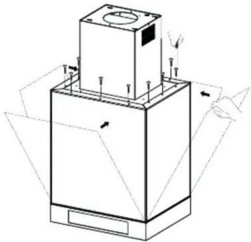
Before fixing the Hood Canopy to the Frame:
- Open the suction panel by pulling it.
- Unfasten the panel from the hood canopy by sliding the fixing pin lever provided.
- Remove the Grease filters from the Hood Canopy.
- Remove any Activated charcoal filters.
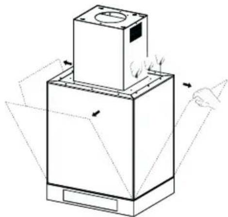
- Working from below, fix the Hood canopy to the Frame provided, using the 4 screws 12f provided.
text_image
12c 12fELECTRICAL CONNECTION
- Connect the Hood to the Mains Power Supply, inserting a bipolar switch with a contact aperture of at least 3 mm.
- Open the Suction Panel and the grease filters, make sure that the power cable is properly inserted into the Suction fan socket
- Hook up the Connectors.
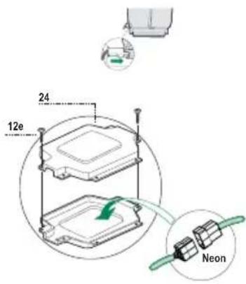
- From the inside, open the Neon lamp wiring box 24 by unfastening the Screws.
- Hook up the remaining free Connector to the one in the Neon lamp wiring box, then close the cover and fit the box in the location provided.
- For the Recirculation Version, fit the Activated Charcoal Odour Filter.
- Replace the Grease Filters and the Suction Panel.
text_image
24 12e NeonFitting Glass Elements
- Fit the Side Glass on the Body (first the bottom then the top) and fix it in place with the Side Glass Bracket 7.1.1 using the Screws 12p provided.
- Fit the Glass Fastener Elements on the Front Glass, fit the latter on the Body (first the bottom then the top) and fix it in place with the Front Glass Bracket 7.1.2 using the Screws 12p provided.
natural_image
Technical line drawing of a mechanical assembly with mounting base and internal components (no text or symbols)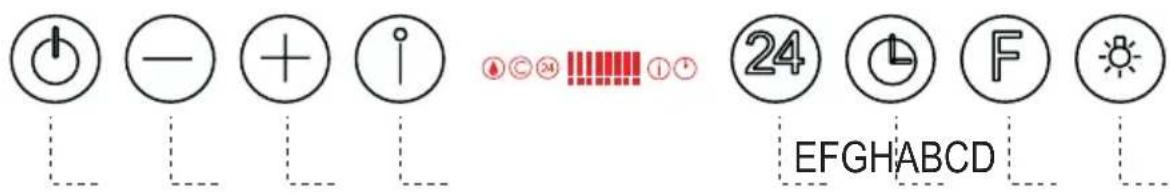
text_image
Power - + i 24 EFGHABCDControl panel
| Button | Function Display | |
| A Turns the suction motor on and off at the last speed used. | Displays the set speed. | |
| B Decrease the working speed. The number of lighted segments decreases. | ||
| C Increase the working speed. The number of lighted segments increases. | ||
| D Activate intensive speed from any other speed, including motor off. This speed is set to operate for 10 minutes, after which the system returns to the speed that was set before. Suitable to deal with maximum levels of cooking fumes. | The indicator I flashes and all the segments on the Display are lit.It is disabled by pressing the Button. | |
| E Starts the Motor at a speed that allows suction of 100 m3/h for 10 minutes per hour, after which the Motor will stop. | Displays 24 and the segments on the Display all light up and then turn off one at a time in cycle.It is disabled by pressing the Button. | |
| F | Activate automatic switch-off with a 30' delay. Suitable to complete elimination of residual odours. Can be activated from any position, and is disabled by pressing the button or turning the motor off. | Displays a flashing Clock symbol.It is disabled by pressing the Button. |
| G | Perform a Reset of the Filter saturation alarm when the Button is pressed for approximately 2 seconds. | After 100 hours in operation the Drop symbol is displayed to indicate saturation of the Metal Grease Filters.After 200 hours in operation the letter C is displayed to indicate saturation of the Activated Charcoal filters. |
| H Turns the lighting system (Spotlights) on and off. Turns the Neon lights on and off when pressed and held for 2 seconds. | ||
Keyboard Lock: it is possible to lock the keyboard, for example when cleaning the Glass, when the Hood has Motor and Lights turned off.
Press D (Intensive) for approximately 5 Seconds to enable or disable the Keyboard Lock, which is always confirmed by a Beep and an animation on the display motor bar.
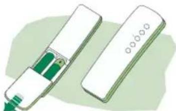
REMOTE CONTROL (OPTIONAL)
The appliance can be controlled using a remote control powered by a 1.5 V carbon-zinc alkaline batteries of the standard LR03-AAA type.
- Do not place the remote control near to heat sources.
• Used batteries must be disposed of in the proper manner.
natural_image
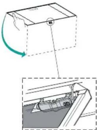
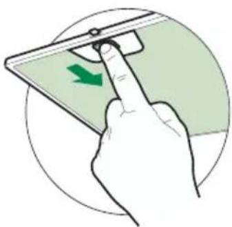
Illustration of a handheld device with green leads and a white rectangular tray (no text or symbols)Cleaning the Comfort Panels
• Pull the Comfort Panel to open it.
- Disconnect the panel from the hood canopy by sliding the fixing pin lever.
- The comfort panel must never be washed in a dishwasher.
- Clean the outside using a damp cloth and neutral liquid detergent.
- Clean the inside as well using a damp cloth and neutral detergent; do not use wet cloths or sponges, or jets of water; do not use abrasive substances.
- When the above operation has been completed, hook the panel back to the hood canopy and close it by turning the knob in the opposite direction.
natural_image
Diagram showing a container with a handle and a side view of a mechanical component (no text or symbols)Metal grease filters
Metal filters can be washed also in a dish machine. They need to be washed every time a drop-symbol appears in the display or at least every two months. In case of very frequent use these have to be washed even more often.
Alarm reset
- Press the G-key for at least 2 seconds.
Cleaning
- Open the comfort panel.
- Remove the filters one by one by pushing them backwards and pulling them down contemporaneously.
- Wash the filters. Pay attention not to bend them. Make sure that filters are completely dry before putting them into their seat. (a possible modification of the filter surface doesn't influence its efficiency).
- Place the filters again into their seats and make sure that the handle of the filter remains outside.
- Close the comfort panel.
natural_image
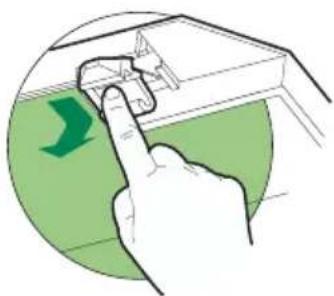
Hand pressing a green arrow on a device screen, enclosed in a circular frame (no text or symbols)This filter cannot be washed or regenerated. It must be replaced when the C appears on the display or at least once every 4 months. The filter saturation alarm has to be activated already before.
Activation of the alarm signal
- In the recycling version hoods the filter saturation alarm must be activated during the installation or later.
- Switch off the hood and the lights.
- Press the E-key for about 5 seconds until the last two segments of the motor LEDs are lit on the display.
- By releasing the E-key the clock icon starts to flash.
- Within 3 seconds press the D-key to activate/deactivate charcoal filter saturation alarm.
• C-symbol lit - charcoal filter saturation alarm ACTIVATED.
• C-symbol unlit - charcoal filter saturation alarm DEACTIVATED.
SUBSTITUTION OF THE CHARCOAL FILTER
Alarm reset
- Switch off the motor and the lighting system.
- Press the G-key for at least 2 seconds.
Substitution of the filter
- Open the comfort panel.
- Remove the metal grease filters.
- Remove the charcoal filter as indicated in the picture.
- Place the filter again into its seat.
- Place again the metal grease filters into their place.
natural_image
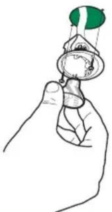
Illustration of a hand pressing down on a green surface with a green arrow indicating direction (no text or symbols)Lighting
LIGHT REPLACEMENT
20 W halogen light.
- Remove the 2 screws fixing the Lighting support, and pull it out of from the Hood.
• Extract the lamp from the Support. - Replace with another of the same type, making sure that the two pins are properly inserted in the lamp holder socket holes.
- Replace the Support, fixing it in place with the two screws removed as above.
natural_image
Line drawing of a hand holding a small object with a green flag on top (no text or symbols)Lighting
CHANGING LAMPS
ATTENTION: When removing the Upper Glass Support Bracket, hold the Glass with the Hand and be careful not to drop it.
16 W neon lamps.
- Unfasten the Screw fixing the head of the Vertical Glass protecting the Neon lamp to be changed.
- Slide the Glass until the end comes free.
- Remove the lamp and replace it with a new one with the same characteristics.
- Reassemble by repeating the above operations in reverse order.
N.B. Should it be necessary to change the Starter, follow the same steps given above for changing the lamp, then replace the component in the upper part of the broken Neon lamp.
natural_image
Technical line drawing of a mechanical assembly with no visible text or symbolsnatural_image
Illustration of a kitchen induction setup with a smokestack emitting vapor and a green X-shaped warning symbol (no text or symbols present)
natural_image
Illustration of a greenhouse with a stove and smokestack emitting vapor, crossed by a green ribbon (no text or symbols)text_image
Technical diagram of a device with numbered parts and exploded view, including labeled components like 7.1a, 7.1b, and 12f.
text_image
347 MIN 780 - MAX 1030 MIN 860 - MAX 1140 650 100 598 **
natural_image
Technical drawing of a square frame with a central circular hole and dimension label (483), no readable text or symbols beyond the dimension line.
text_image
21.5 85 76.3 287.5 135 76.3 750 Min. 650mm Min. 650mmnatural_image
Technical diagram of a mechanical assembly with a base and mounting bracket, showing alignment lines (no text or symbols)natural_image
Technical illustration of a screwdriver inserted into a mechanical assembly (no text or symbols)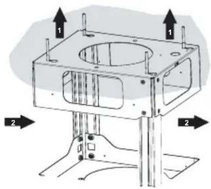
text_image
Technical diagram of a mechanical assembly with labeled components and directional arrows indicating motion or force directions.Branchements
SORTIE AIR VERSION ASPIRANTE
natural_image
Technical line drawing of a mechanical assembly with mounting base and internal components (no text or symbols)
text_image
EFGHABCDTableau de commande
natural_image
Illustration of two electronic devices with green leads, one emitting a probe (no text or symbols)Nettoyage des Confort Panel
natural_image
Diagram showing a car interior with a moving vehicle and a magnified view of the dashboard (no text or symbols)natural_image
Illustration of a hand pressing a green arrow on a device screen (no text or symbols)REEMPLACEMENT DU FILTRE ANTI-ODEUR AU CHARBON ACTIF
natural_image
Illustration of a hand pressing down on a green surface with a green arrow indicating direction (no text or symbols)Eclairage
REMLACEMENT LAMPES
natural_image
Line drawing of a hand holding a small object with a green flag on top (no text or symbols)Éclairage
REEMPLACEMENT DES AMPOULES
natural_image
Technical line drawing of a mechanical device with internal components and directional arrows indicating motion (no text or symbols)natural_image
Illustration of a kitchen induction setup with a smokestack emitting vapor, a control panel, and a green X-shaped warning symbol (no text or labels)
natural_image
Illustration of a greenhouse with a stove and smokestack emitting vapor, crossed by a green ribbon (no text or symbols)text_image
Exploded view diagram of a mechanical device with numbered parts and exploded views
text_image
MIN 780 - MAX 1030 MIN 860 - MAX 1140 650 100 598 347
natural_image
Technical drawing of a square frame with a central circular hole and dimension label (483), no readable text or symbols beyond the dimension line.
text_image
21.5 85 76.3 287.5 135 76.3 750 Min. 650mm Min. 650mm* Abmessungen der Haube in Abluftversion.
** Abmessungen der Haube in Umluftversion.
natural_image
Technical diagram of a mechanical assembly with a base and mounting bracket, showing alignment lines (no text or symbols)natural_image
Technical illustration of a screwdriver inserted into a mechanical component, showing internal components and assembly (no text or symbols)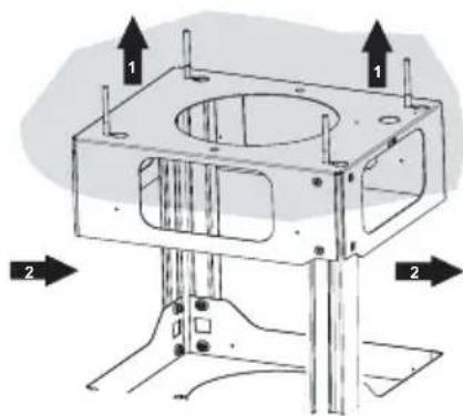
text_image
Technical diagram of a mechanical assembly with numbered components and directional arrows indicating motion or force directions.Anschlüsse
natural_image
Technical line drawing of a mechanical assembly with mounting base and internal components (no text or symbols)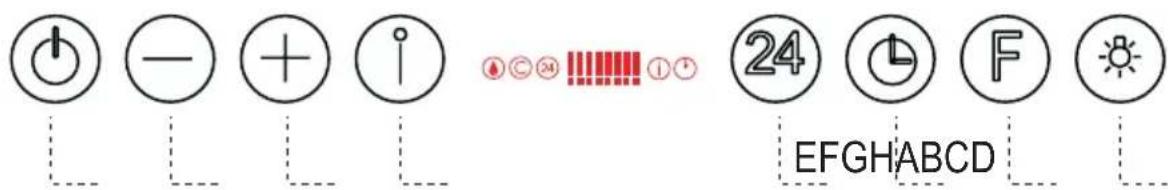
text_image
24 EFGHABCDSchalttafel
natural_image
Illustration of two electronic devices with green connectors and a display screen (no text or symbols)natural_image
Diagram showing a car interior with a moving box and a magnified view of the dashboard (no text or symbols)Metallfettfilter
natural_image
Hand holding a smartphone with a green directional arrow on screen (no text or symbols)natural_image
Illustration of a hand pressing down on a device component with a green arrow indicating left motion (no text or symbols)Beleuchtung
AUSWECHSELN DER LAMPEN
Halogenlampe 20 W
natural_image
Line drawing of a hand holding a small object with a green flag above (no text or symbols)Beleuchtung
AUSWECHSELN DER LAMPE
natural_image
Technical line drawing of a mechanical device with no visible text or symbolsnatural_image
Illustration of a kitchen induction setup with a smokestack emitting vapor and a control panel (no text or symbols)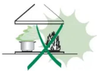
natural_image
Illustration of a greenhouse with a pot and smokestack emitting vapor, crossed by a green ribbon (no text or symbols)text_image
Technical diagram of a device with labeled parts and exploded view, including zoomed-in views and numbered components.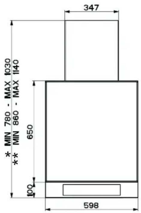
text_image
347 MIN 780 - MAX 1030 MIN 860 - MAX 1140 650 100 598 **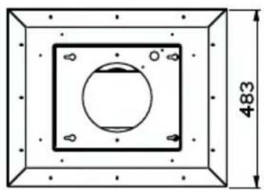
natural_image
Technical drawing of a square frame with a central circular hole and dimension label (483), no readable text or symbols beyond the dimension line.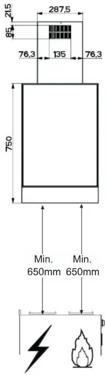
text_image
21.5 85 76.3 287.5 135 76.3 750 Min. 650mm Min. 650mmnatural_image
Technical diagram of a mechanical assembly with a base and mounting bracket, showing alignment lines (no text or symbols)Gaten boren in plafond/plank en bevestiging frame
GATEN BOREN IN PLAFOND/PLANK
natural_image
Technical illustration of a screwdriver inserted into a mechanical assembly (no text or symbols)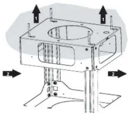
text_image
Technical diagram of a mechanical assembly with labeled components and directional arrows indicating motion or force directions.Aansluitingen
LUCHTUITLAAT AFZUIGVERSIE
natural_image
Technical line drawing of a mechanical assembly with mounting base and internal components (no text or symbols)
text_image
EFGHABCDBedieningspaneel
natural_image
Illustration of two electronic devices with green leads, one emitting a probe (no text or symbols)natural_image
Diagram showing a mechanical component with a rotating arrow and a close-up view of its internal structure (no text or symbols)Metalen Vetfilters
natural_image
Hand holding a smartphone with a green directional arrow indicating left touch (no text or symbols)natural_image
Illustration of a hand pressing down on a green surface with a green arrow indicating direction (no text or symbols)Verlichting
VERVANGING VAN DE LAMPEN
natural_image
Line drawing of a hand holding a small object with a green flag on top (no text or symbols)Verlichting
VERVANGEN VAN DE LAMPEN
natural_image
Technical line drawing of a mechanical assembly with no visible text or symbolsCE