
PDPS65 - Pregnant PIONEER - Free user manual and instructions
Find the device manual for free PDPS65 PIONEER in PDF.

| Product type | Bass-reflex acoustic speaker, 2-way |
| Weight (speaker only) | 3.15 kg |
| Weight with accessories | 3.7 kg |
| Power supply | Passive (connection to Pioneer TV) |
| Maximum input power | 18 W |
| Rated power | 6 W |
| Impedance | 6 Ω |
| Frequency response | 55 Hz – 30,000 Hz |
| Sensitivity (1 m, 1 W) | 80 dB |
| Crossover frequency | 3 kHz |
| Woofer | 4.8 cm × 13 cm cone |
| Tweeter | 2.5 cm semi-dome |
| Care and cleaning | Soft dry or slightly damp cloth. Do not use chemical products. |
| Safety | Installation by two persons, use only provided screws, do not move the TV by the speakers. |
| Spare parts and repairability | Contact an authorized Pioneer service center. |
| General information | Designed exclusively for Pioneer flat-screen TV. Brackets and cables provided. |
Frequently Asked Questions - PDPS65 PIONEER
User questions about PDPS65 PIONEER
0 question about this device. Answer the ones you know or ask your own.
Ask a new question about this device
Download the instructions for your Pregnant in PDF format for free! Find your manual PDPS65 - PIONEER and take your electronic device back in hand. On this page are published all the documents necessary for the use of your device. PDPS65 by PIONEER.
USER MANUAL PDPS65 PIONEER
OPERATING INSTRUCTIONS
MODE D'EMPLOI
BEDIENUNGSANLEITUNG
ISTRUZIONI PER L'USO
HANDLEIDING
Thank you for buying this Pioneer product.
Please read through these operating instructions before using your speaker system so you will know how to make the most of its performance. After you have finished reading the instructions, put them away in a safe place for future reference.
CAUTION
About compatibility
This product is designed exclusively for use with the Pioneer flat screen TV. For more information on compatibility, please consult with your nearest Pioneer authorized dealer or service center.
About installation and setting
- Do not move the flat screen TV by holding the speaker or speaker brackets. This could result in injury or damage to the brackets. When moving the TV, hold by the top and handles.
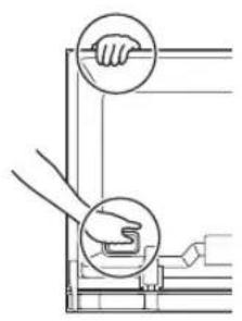
natural_image
Diagram showing two hands operating a tool with circular annotations highlighting the handle (no text or symbols present)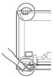
- The speaker is wide, and may become unstable when installed by a one person alone. This may result in injury or product damage. Therefore, at least two people must assemble and install them.
- When installing the speaker, do not use any screws other than those supplied, otherwise the speaker may come off from the main unit and fall over.
- When installing the speaker, tighten the screws firmly.
- Please handle the speaker with sufficient care, as the grille net and the cabinet can become damaged or broken when they are subjected to strong external impacts.
- Placing a CRT computer screen or CRT monitor near to the speaker may result in interference or color distortion. If this happens, distance the monitor from the speaker.
About the input
- In order to prevent damage to the speaker system resulting from input overload, please observe the following precautions:
- Do not connect this speaker to anything other than the specified flat screen TV. Doing so may result in damage or fire.
- Be sure to turn the connected devices off and remove the power cord from the wall outlet beforehand when changing the connection or installation method.
- When using a tone control function to greatly emphasize treble sounds, do not use excessive amplifier volume.
CHECKING THE ACCESSORIES
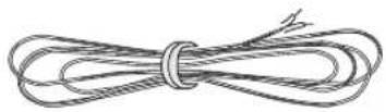
- Speaker Cables × 2
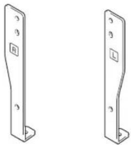
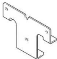
• Speaker Brackets (Left and Right)
natural_image
Two identical metal bracket components with mounting holes and mounting holes, shown side by side (no text or symbols)- Speaker Bracket (Center)
natural_image
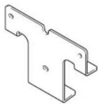
Technical line drawing of a T-shaped metal bracket (no text or symbols)- Speaker Mounting Screws (M5 × 10 mm : Black) × 9

- Operating Instructions
Installation
- Consult your dealer if you encounter any difficulties with this installation.
- Pioneer is not liable for any damage resulting from improper installation, improper use, modification, or natural disasters.
INSTALLATION ON THE FLAT SCREEN TV
Flat screen TV with the speaker installed
When using the table top stand:

NOTE:
Before attaching the speaker, please attach the PDK-TS35 series table top stand (or another Pioneer flat screen TV stand) to the flat screen TV.
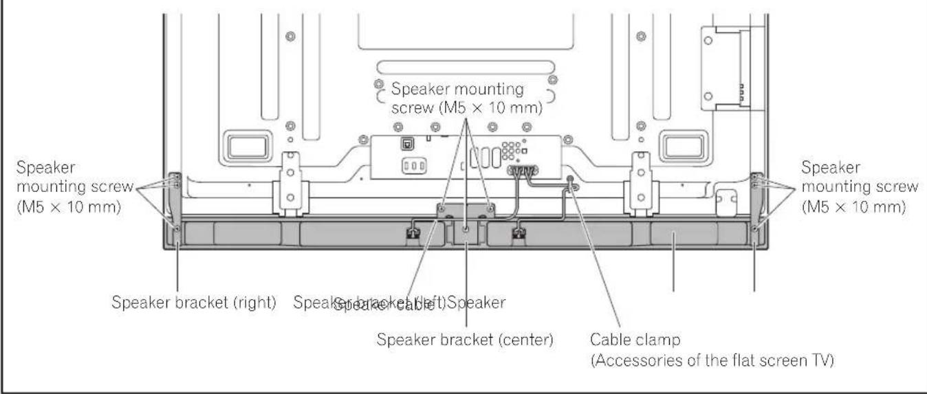
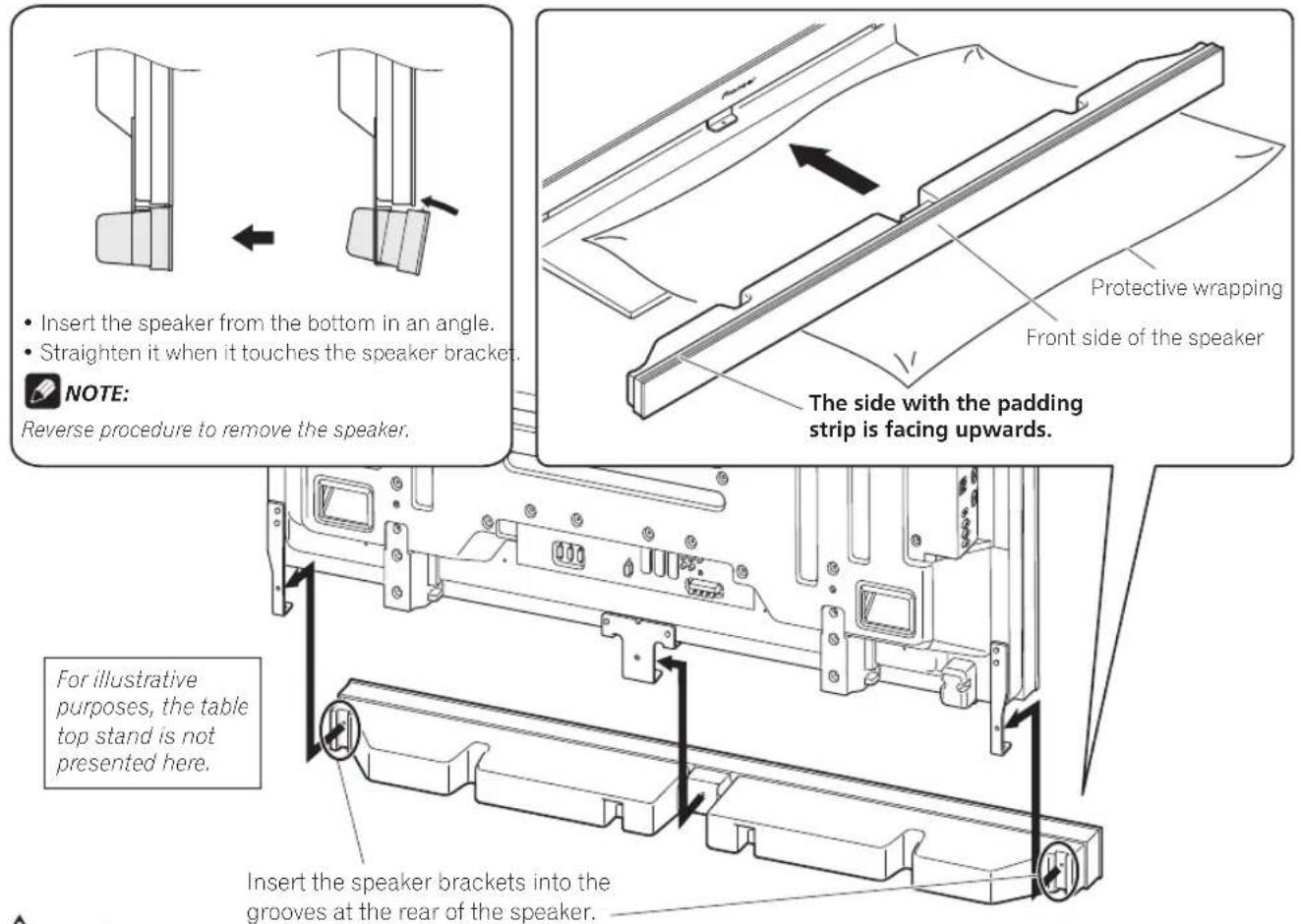
1. Attach the speaker brackets to the rear of the flat screen TV.
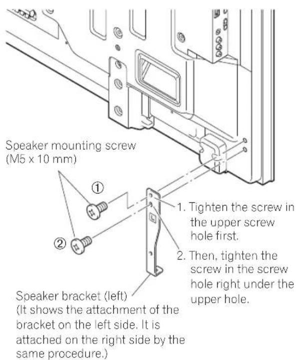
- Attach the brackets for right and left sides to the bottom right and left on the rear panel of the flat screen TV using the supplied screws.
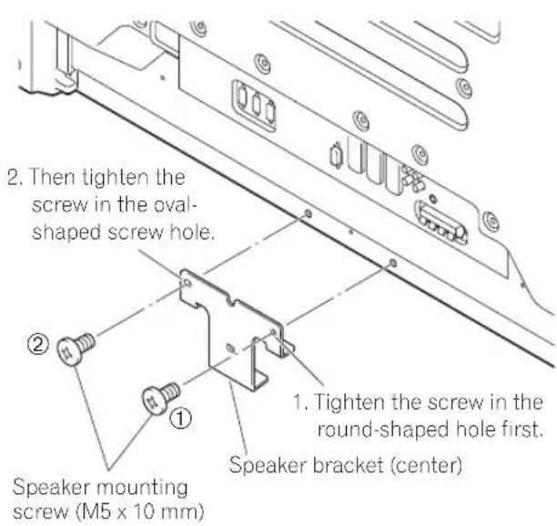
- Attach the bracket for center to the lower center on the rear panel of the flat screen TV using the two supplied screws.
2. Fit the speaker to the brackets in the correct direction.
- Be sure not to mount the speaker upside down.

Caution
- To avoid any damage to the speaker and/or table top stand from striking against each other, fit the speaker to the bracket while confirming their locations. As you may easily strike the stand, use the protective wrapping in which the speaker was wrapped between the speaker and stand.
- When the speaker brackets do not fit the grooves at the rear of the speaker, adjust the speaker brackets angle.
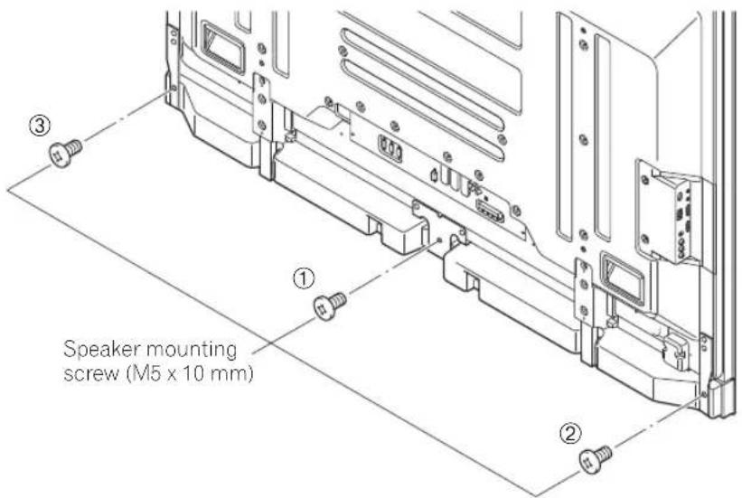
3. Tighten from back using the supplied screws (three locations).
- Tighten the three screws in order ①, ②, ③ as shown in the diagram.

CAUTION
Do not move the flat screen TV holding on to the bracket. This can result in injury or damage to the flat screen TV.
The screw hole at the bottom surface of the speaker bracket is used when the flat screen TV is installed on the wall. It is not used when installed with the stand.

NOTE:
If after attaching the speaker its position needs to be adjusted horizontally or vertically, first loosen the speaker mounting screws, reposition and then tighten the screws again at the appropriate position.
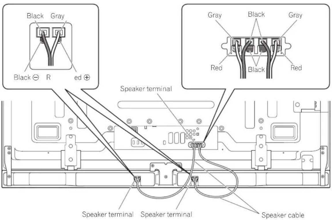
4. Connect the supplied the speaker cables to the speaker.
- Connect the cables correctly with respect to the polarity of the speaker terminals, that is, ⊕ cable (Gray) to ⊕ terminals (Red) and ⊖ cable (Black) to ⊖ terminals (Black).
5. Connect the other end of the speaker cables to the rear of flat screen TV.
- Connect the cables correctly with respect to the polarity of the flat screen TV speaker terminals, that is, ⊕ cable (Gray) to ⊕ terminals (Red) and ⊖ cable (Black) to ⊖ terminals (Black).
For illustrative purposes, the table top stand is not presented here.

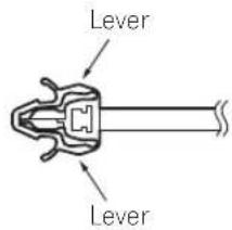
NOTE:
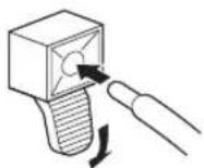
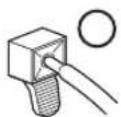
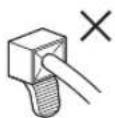
- Press the lever and insert the end of the cable.
- When you release the lever, it clamps onto the speaker cable.

Caution
- Be sure to turn the connected devices off and remove the power cord from the wall outlet beforehand when changing the connection or installation method.
- If you insert the speaker cable too far so that the insulation is touching the speaker terminal, you may not get any sound. Please insert it with showing the copper wire.
- Check if the end of the speaker cables are securely connected to the terminals by slightly tugging on the cable after making connections. Loose connections may result in sound dropouts or noise.
- If there is a short in the and cables caused by an exposed lead wire, excessive load may be applied to the flat screen TV, resulting in interrupted operation or malfunction.
- Incorrect connections of the speaker cable to the right or left of the flat screen TV terminals with respect to the polarity may result in insufficient stereo sound effects, delivering poor bass sounds or unstable sound image.
- Bundle the cable without pulling.
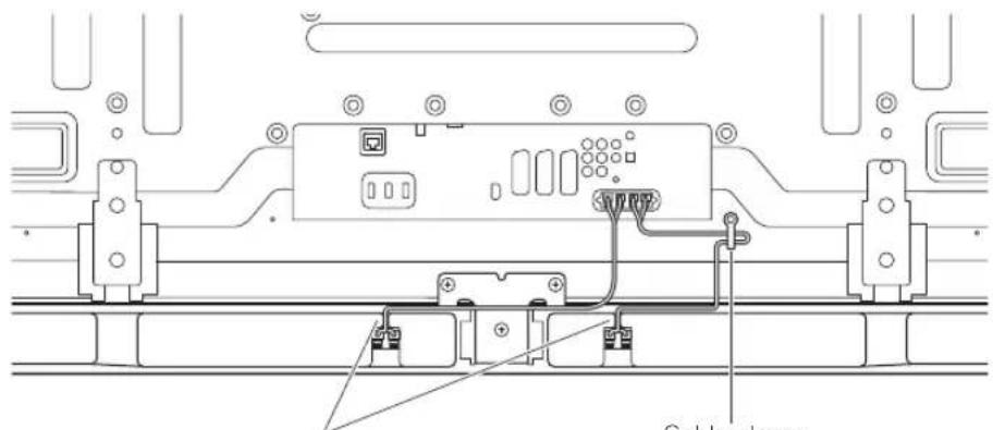
6. Fit the cables into the groove of the speaker.
7. Bundling the cables.
Follow the steps below to attach a cable clamp.
1) Thread the clamp band through the holder and bundle the cable(s) in the cable clamp.
2) Push and hold the levers then insert the hook into an appropriate hole on the rear of the flat screen TV.
3) Pull up the clamp band to lock.
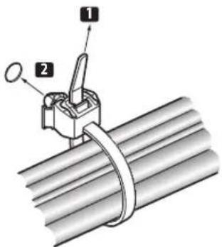
4) Confirm that the cable clamp is seated firmly in the panel.

NOTE:
Avoid pinching or creating pressure points when routing or bundling cables.
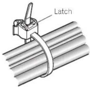
To remove the clamp band, pull and hold the latch to release.
To remove the cable clamp, push and hold the levers then pull it out from the hole.

TE:
The longer a clamp is in place, the better chance of deterioration. An older clamp is more easily damaged while being removed and may not be reusable.
▼ Rear of flat screen TV
Fit the cables into the groove of the speaker.
When using the hung on wall unit:

NOTE:
First lay the flat screen TV on top of a soft sheet etc., then attach the speaker brackets.
- Attach the speaker brackets to the rear of the flat screen TV (See procedure 1 on page 3).
-
Connect the supplied speaker cables to the rear of the flat screen TV (See procedure 5 on page 5).
-
Connect the other cables and power cord to the flat screen TV.
- Place the flat screen TV on the mounting fittings of the hung on wall unit.
- For details, refer to the operating instructions supplied with the hung on wall unit.

Caution
Be careful about the speaker brackets when installing or connecting. This may result in injury.
- Connect the other end of the speaker cables to the speaker (See procedure 4 on page 5).

Caution
Have two people perform this procedure.
- Fit the speaker to the brackets the correct direction.
- Be sure not to mount the speaker upside down.
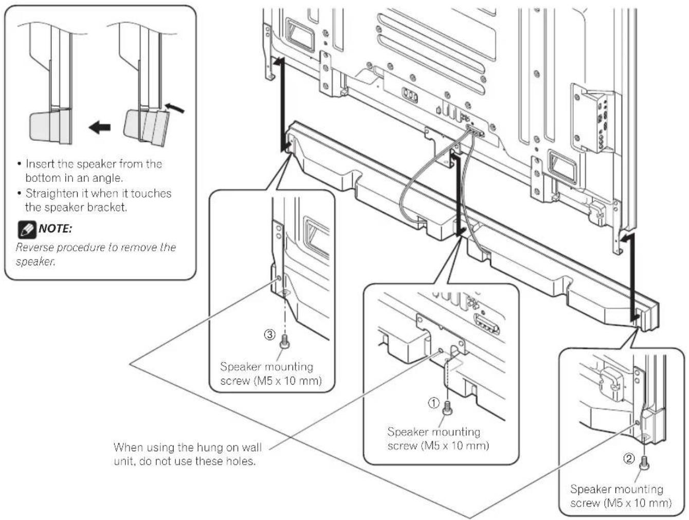
6. Tighten from below using the supplied screws (three locations).
- Tighten the three screws in order ①, ②, ③ as shown in the diagram (see page 7). The screw hole at the rear surface of the speaker bracket is used when the flat screen TV is installed with the table top stand. It is not used when installed on the wall.

NOTE:
If after attaching the speaker its position needs to be adjusted horizontally, first loosen the speaker mounting screws, reposition and then tighten the screws again at the appropriate position.
7. Bundling the cables (See procedure 7 on page 6).
CABINET MAINTENANCE
- Use a polishing cloth or dry cloth to wipe off dust and dirt.
- When the cabinet is very dirty, wipe with a soft cloth moistened with water-diluted cleanser; then wipe again with a dry cloth. Do not use furniture wax or cleaners. They may damage the surface of the cabinet.
- Never use thinner, benzine, insecticide sprays and other chemicals on or near the cabinets, since these will corrode the surfaces.
- When a chemical cloth is used, read the cautions for the chemical cloth carefully.
SPECIFICATIONS
Cabinet ...... Bass-reflex type
Used speaker (two-way system):
Woofer (for low tones) .... 4.8 cm × 13 cm cone type Tweeter (for high tones) .... 2.5 cm semidome type Impedance .... 6 Ω
Frequency Range ....55 Hz to 30 000 Hz
Sensitivity (1 m, 1 W) 80 dB
Permissible input :
Max. input 18 W Rated input 6 W
Crossover frequency 3 kHz
External Dimensions 1 465 (W) mm × 78 (H) mm × 93 (D) mm
Weight :
Speaker only ....3.15 kg With cables, brackets and screws .... 3.7 kg
Accessory parts .....Speaker Cables × 2 .....Speaker Brackets
Left ×1
Right ×1
Center ×1
Speaker Mounting Screws (M5 × 10 mm) × 9
Operating Instructions x 1
NOTE:
Specifications and design subject to possible modification without notice, due to improvements.
IMPORTANT NOTICE – RECORD THE MODEL NUMBER AND SERIAL NUMBERS OF THIS EQUIPMENT BELOW. THE NUMBERS ARE ON THE REAR.
MODEL NO. ____
SERIAL NO. ____
KEEP THESE NUMBERS FOR FUTURE USE.
D1-4-2-6-2_En
If you want to dispose this product, do not mix it with general household waste. There is a separate collection system for used electronic products in accordance with legislation that requires proper treatment, recovery and recycling.
Private households in the member states of the EU, in Switzerland and Norway may return their used electronic products free of charge to designated collection facilities or to a retailer (if you purchase a similar new one).
For countries not mentioned above, please contact your local authorities for the correct method of disposal.
By doing so you will ensure that your disposed product undergoes the necessary treatment, recovery and recycling and thus prevent potential negative effects on the environment and human health. K058 A
K058 A En
Published by Pioneer Corporation.
Copyright © 2008 Pioneer Corporation.
All rights reserved.
natural_image
Diagram showing two hands operating a mechanical device with no visible text or symbols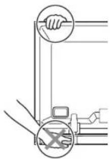
natural_image
Two identical isometric metal bracket diagrams with mounting holes and mounting points, no text or symbols present.natural_image
Technical line drawing of a T-shaped metal bracket (no text or symbols)1 465 (L) mm × 78 (H) mm × 93 (P) mm
Poids :
Publication de Pioneer Corporation.
© 2008 Pioneer Corporation.
natural_image
Technical diagram showing two hands operating a mechanical component, with no visible text or symbols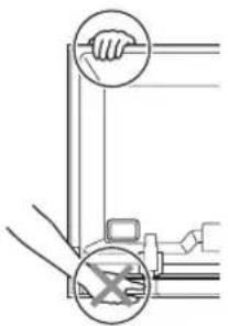
natural_image
Two identical metal bracket components with mounting holes and mounting holes, shown side by side (no text or symbols)natural_image
Technical line drawing of a T-shaped metal bracket (no text or symbols)natural_image
Technical line drawing showing two hands operating a mechanical component (no text or symbols)
natural_image
Two identical metal bracket components with mounting holes and mounting holes, shown side by side (no text or symbols)natural_image
Technical line drawing of a T-shaped metal bracket (no text or symbols)Copyright © 2008 Pioneer Corporation.
natural_image
Two identical metal bracket components with mounting holes and mounting holes, shown side by side (no text or symbols)• Luidsprekerbeugel (Midden)

natural_image
Technical line drawing of a T-shaped metal bracket (no text or symbols)Copyright © 2008 Pioneer Corporation.
natural_image
Diagram showing two hands operating a mechanical device with a handle and a tool, no text or symbols present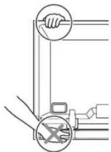
natural_image
Two identical metal bracket components with mounting holes and mounting holes, shown side by side (no text or symbols)natural_image
Technical line drawing of a T-shaped metal bracket with mounting holes (no text or symbols)Copyright © 2008 Pioneer Corporation.
natural_image
Two identical metal bracket components with mounting holes and mounting holes, shown side by side (no text or symbols)- 揚聲器固定裝置(中央)
natural_image
Technical line drawing of a T-shaped metal bracket (no text or symbols)4) 確認扎線扣是否確實安裝在面板上。

備註:
natural_image
Diagram showing two hands operating a mechanical device with circular annotations indicating contact points (no text or symbols present)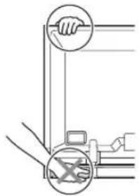
natural_image
Two identical metal bracket components with mounting holes and mounting holes, shown side by side (no text or symbols)natural_image
Isometric line drawing of a T-shaped metal bracket with mounting holes (no text or symbols)natural_image
Technical line drawing of a mechanical or electronic component assembly with no visible text or symbolsDiscover the benefits of registering your product online at
http://www.pioneer.co.uk (or http://www.pioneer.eu).
PIONEER ELECTRONICS (USA) INC.
P.O. BOX 1540, Long Beach, California 90801-1540, U.S.A. TEL: (800) 421-1404
PIONEER ELECTRONICS OF CANADA, INC.
300 Allstate Parkway, Markham, Ontario L3R 0P2, Canada TEL: 1-877-283-5901, 905-479-4411
PIONEER EUROPE NV
Haven 1087, Keetberglaan 1, B-9120 Melsele, Belgium TEL: 03/570.05.11
PIONEER ELECTRONICS ASIACENTRE PTE. LTD.
253 Alexandra Road, #04-01, Singapore 159936 TEL: 65-6472-7555
PIONEER ELECTRONICS AUSTRALIA PTY. LTD.
178-184 Boundary Road, Braeside, Victoria 3195, Australia, TEL: (03) 9586-6300
PIONEER ELECTRONICS DE MEXICO S.A. DE C.V.
Blvd.Manuel Avila Camacho 138 10 piso Col.Lomas de Chapultepec, Mexico, D.F. 11000 TEL: 55-9178-4270
K002_B_En
Published by Pioneer Corporation.
Copyright © 2008 Pioneer Corporation.
All rights reserved.
Publication de Pioneer Corporation.
© 2008 Pioneer Corporation.

- CAUTION
- About compatibility
- About installation and setting
- About the input
- CHECKING THE ACCESSORIES
- Installation
- INSTALLATION ON THE FLAT SCREEN TV
- When using the table top stand:
- NOTE:
- Attach the speaker brackets to the rear of the flat screen TV.
- Fit the speaker to the brackets in the correct direction.
- Tighten from back using the supplied screws (three locations).
- Connect the supplied the speaker cables to the speaker.
- Connect the other end of the speaker cables to the rear of flat screen TV.
- Fit the cables into the groove of the speaker.
- Bundling the cables.
- TE:
- When using the hung on wall unit:
- Tighten from below using the supplied screws (three locations).
- Bundling the cables (See procedure 7 on page 6).
- CABINET MAINTENANCE
- SPECIFICATIONS
- 備註:
- PIONEER ELECTRONICS (USA) INC.
- PIONEER ELECTRONICS OF CANADA, INC.
- PIONEER EUROPE NV
- PIONEER ELECTRONICS ASIACENTRE PTE. LTD.
- PIONEER ELECTRONICS AUSTRALIA PTY. LTD.
- PIONEER ELECTRONICS DE MEXICO S.A. DE C.V.
Brand : PIONEER
Model : PDPS65
Category : Pregnant