BTW250 - Drill MAKITA - Free user manual and instructions
Find the device manual for free BTW250 MAKITA in PDF.
User questions about BTW250 MAKITA
0 question about this device. Answer the ones you know or ask your own.
Ask a new question about this device
Download the instructions for your Drill in PDF format for free! Find your manual BTW250 - MAKITA and take your electronic device back in hand. On this page are published all the documents necessary for the use of your device. BTW250 by MAKITA.
USER MANUAL BTW250 MAKITA
GB Cordless Impact Wrench Instruction Manual
natural_image
Line drawing of a Makada electric drill with attached battery pack (no text or symbols)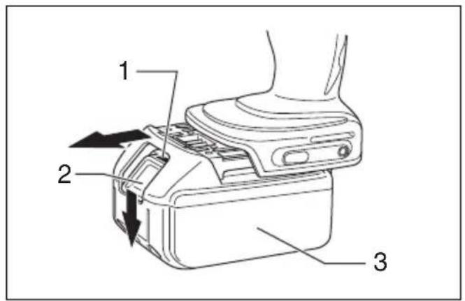
text_image
1 2 31

text_image
Daikita 42
text_image
Tuckita 53
text_image
A 6 B4
text_image
7 85
text_image
7 10 96
text_image
13 12 117
natural_image
Line drawing of a hand using a drill bit to lift a power tool (no text or symbols)8
line
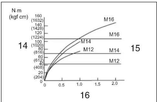
| M | Value | |------|-------| | M16 | 1632 | | M16 | 1428 | | M16 | 1224 | | M14 | 1020 | | M14 | 816 | | M14 | 612 | | M12 | 408 | | M12 | 204 |9
GB Standard bolt
F Boulon standard
D Standardschrauben
I Bullone standard
NL Standaard bout
E Tornillo estándar
P Porca normal
DK Standardbolt
S Standardbult
N Standardbolt
FIN Nornaali pultti
GR Kavovikó μπουλόνι
line
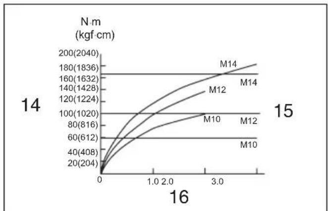
| x | M10 | M12 | M14 | | ---- | ------- | ------- | ------- | | 0 | 20(204) | 40(408) | 60(612) | | 1.0 | 80(816) | 100(1020) | 120(1224) | | 2.0 | 120(1224) | 140(1428) | 160(1632) | | 3.0 | 160(1632) | 180(1836) | 200(2040) |10
GB High tensile bolt
F Boulon à haute résistance
D HV-Schrauben
I Bullone altamente tensile
NL Bout met grote treksterkte
E Tornillo de alta resistencia
P Porca de grande elasticidade
DK Kvalitetsstålbolt
S Bult met hög hållfasthet
N Høy streskkbolt
FIN Suurvetolujuuspultti
GR Μπουλόνι υψηλής
εκτατικότητος
text_image
1711 12
text_image
18 19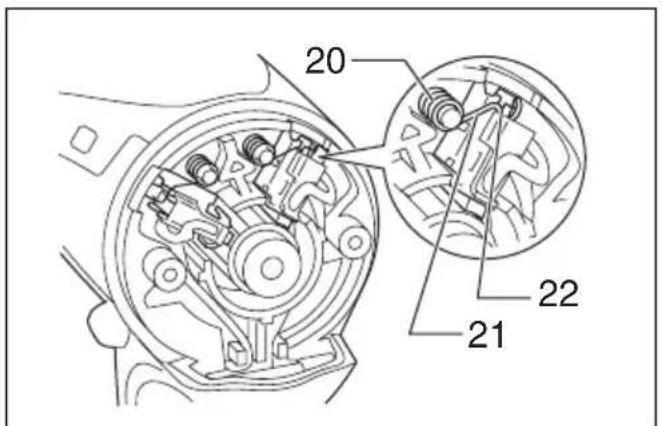
text_image
20 21 22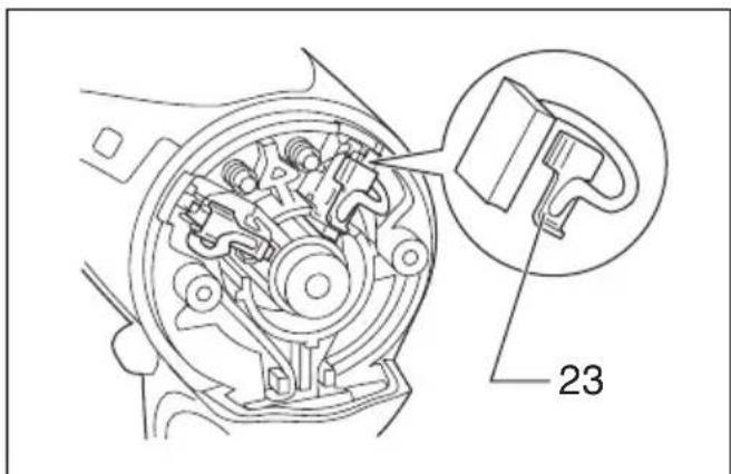
text_image
2313 14
text_image
24 2315
ENGLISH
| Explanation of general view | ||
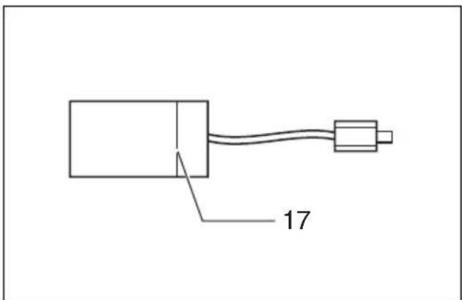
| 1 Red part | 9 P i n | 17 Limit mark |
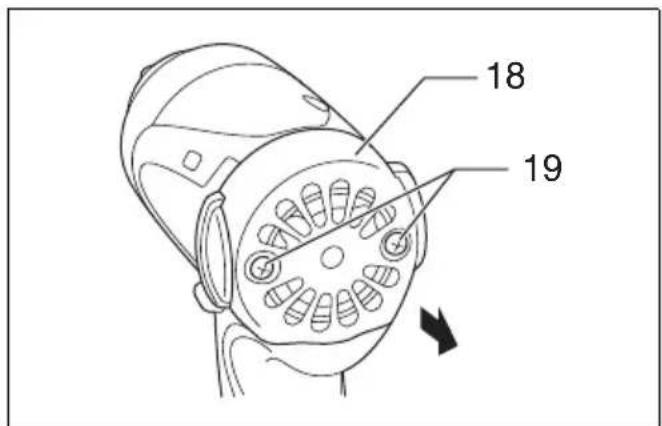
| 2 Button | 10 O-ring | 18 Rear cover |
| 3 Battery cartridge | 11 Hook | 19 Screws |
| 4 Switch trigger | 12 Screw | 20 Spring |
| 5 L a m p | 13 Groove | 21 Arm |
| 6 Reversing switch lever | 14 Fastening torque | 22 Recessed part |
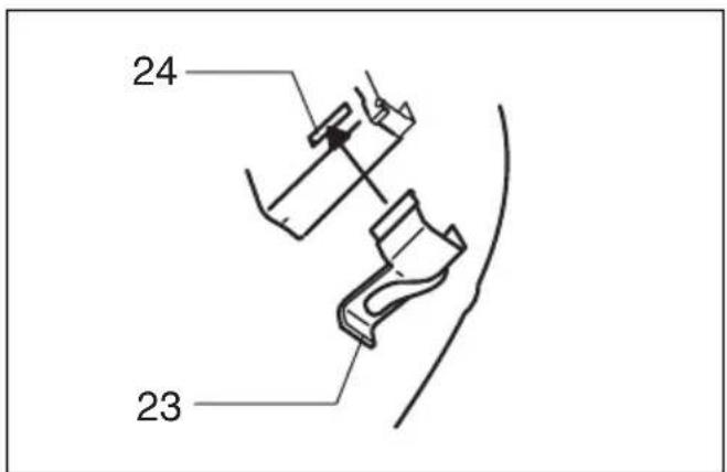
| 7 Socket | 15 Proper fastening torque | 23 Carbon brush cap |
| 8 Anvil | 16 Fastening time | 24 Hole |
SPECIFICATIONS
| Model BTW250 BTW251 | |||
| Capacities | Standard bolt | M10 – M16 | M10 – M16 |
| High tensile bolt | M10 – M14 | M10 – M14 | |
| Square drive 12.7 mm 12.7 mm | |||
| No load speed (min ^-1 ) | 0 – 2,200 | 0 – 2,100 | |
| Impacts per minute | 0 – 3,200 | 0 – 3,200 | |
| Max. fastening torque | 230 N•m | 230 N•m | |
| Overall length | 165 mm | 165 mm | |
| Net weight | 1.6 kg | 1.7 kg | |
| Rated voltage | D.C. 14.4 V | D.C. 18 V | |
- Due to our continuing program of research and development, the specifications herein are subject to change without notice.
- Note: Specifications may differ from country to country.
Intended use
The tool is intended for fastening bolts and nuts.
Safety Hints
For your own safety, please refer to the enclosed safety instructions.
SPECIFIC SAFETY RULES
GEB009-2
DO NOT let comfort or familiarity with product (gained from repeated use) replace strict adherence to impact wrench safety rules. If you use this tool unsafely or incorrectly, you can suffer serious personal injury.
- Hold tool by insulated gripping surfaces when performing an operation where the cutting tool may contact hidden wiring or its own cord. Contact with a "live" wire will make exposed metal parts of the tool "live" and shock the operator.
- Wear ear protectors.
- Check the socket carefully for wear, cracks or damage before installation.
- Hold the tool firmly.
- Always be sure you have a firm footing. Be sure no one is below when using the tool in high locations.
- The proper fastening torque may differ depending upon the kind or size of the bolt. Check the torque with a torque wrench.
SAVE THESE INSTRUCTIONS.
WARNING:
MISUSE or failure to follow the safety rules stated in this instruction manual may cause serious personal injury.
IMPORTANT SAFETY INSTRUCTIONS FOR BATTERY CARTRIDGE
ENC007-2
- Before using battery cartridge, read all instructions and cautionary markings on (1) battery charger, (2) battery, and (3) product using battery.
- Do not disassemble battery cartridge.
- If operating time has become excessively shorter, stop operating immediately. It may result in a risk of overheating, possible burns and even an explosion.
- If electrolyte gets into your eyes, rinse them out with clear water and seek medical attention right away. It may result in loss of your eyesight.
- Do not short the battery cartridge:
(1) Do not touch the terminals with any conductive material.
(2) Avoid storing battery cartridge in a container with other metal objects such as nails, coins, etc.
(3) Do not expose battery cartridge to water or rain.
A battery short can cause a large current flow, overheating, possible burns and even a breakdown.
-
Do not store the tool and battery cartridge in locations where the temperature may reach or exceed 50^ C ( 122^ F).
-
Do not incinerate the battery cartridge even if it is severely damaged or is completely worn out. The battery cartridge can explode in a fire.
-
Be careful not to drop or strike battery.
SAVE THESE INSTRUCTIONS.
Tips for maintaining maximum battery life
- Charge the battery cartridge before completely discharged. Always stop tool operation and charge the battery cartridge when you notice less tool power.
- Never recharge a fully charged battery cartridge. Overcharging shortens the battery service life.
- Charge the battery cartridge with room temperature at 10^ C – 40^ C ( 50^ F – 104^ F). Let a hot battery cartridge cool down before charging it.
FUNCTIONAL DESCRIPTION
CAUTION:
- Always be sure that the tool is switched off and the battery cartridge is removed before adjusting or checking function on the tool.
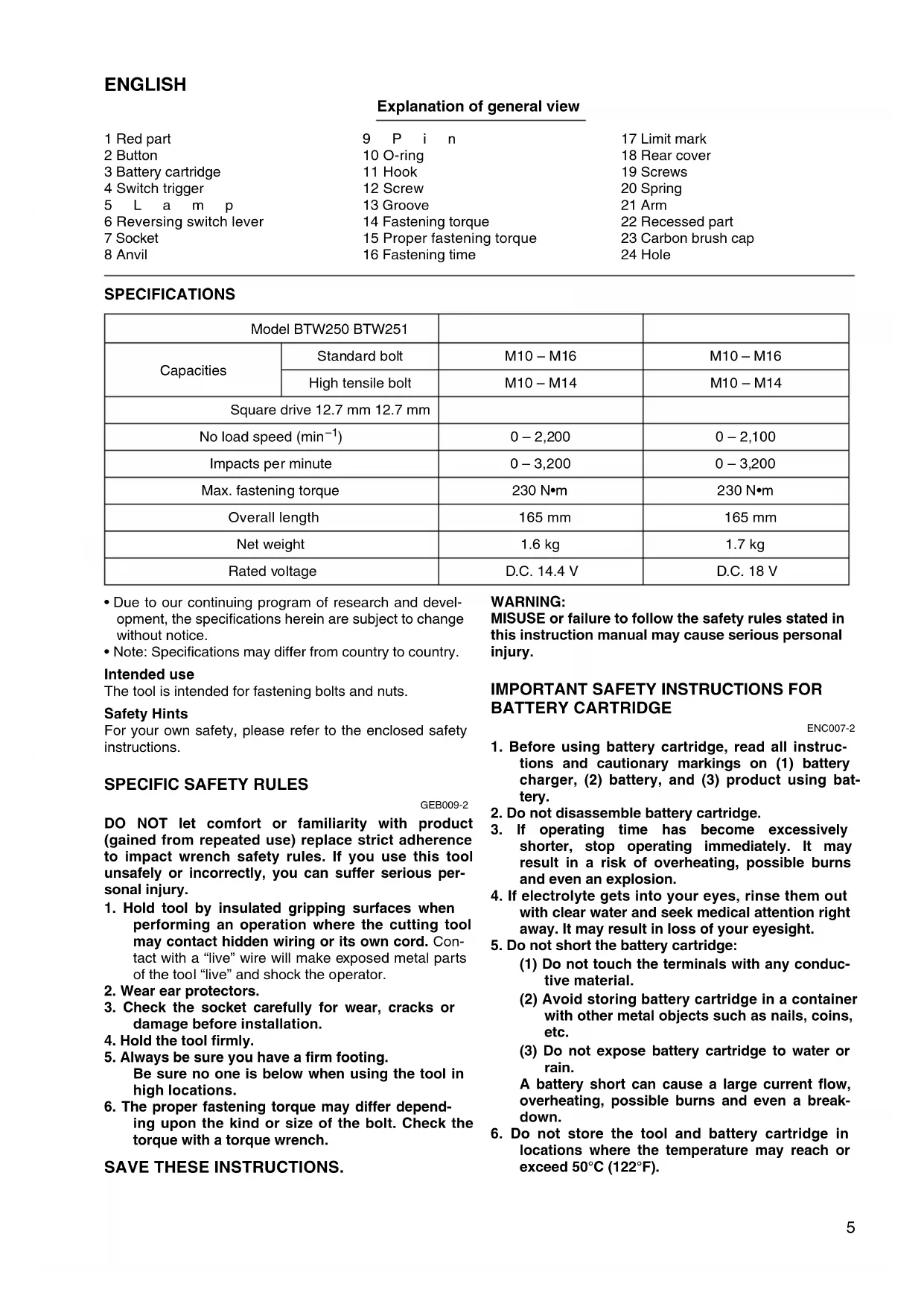
Installing or removing battery cartridge (Fig. 1)
- Always switch off the tool before insertion or removal of the battery cartridge.
- To remove the battery cartridge, withdraw it from the tool while sliding the push button on the front of the cartridge.
- To insert the battery cartridge, align the tongue on the battery cartridge with the groove in the housing and slip it into place. Always insert it all the way until it locks in place with a little click. If you can see the red part on the upper side of the button, it is not locked completely. Insert it fully until the red part cannot be seen. If not, it may accidentally fall out of the tool, causing injury to you or someone around you.
- Do not use force when inserting the battery cartridge. If the cartridge does not slide in easily, it is not being inserted correctly.
Switch action (Fig. 2)
CAUTION:
- Before inserting the battery cartridge into the tool, always check to see that the switch trigger actuates properly and returns to the "OFF" position when released.
To start the tool, simply pull the switch trigger. Tool speed is increased by increasing pressure on the switch trigger. Release the switch trigger to stop.
Lighting up the front lamp (Fig. 3)
CAUTION:
- Do not look in the light or see the source of light directly.
Pull the switch trigger to light up the lamp. The lamp keeps on lighting while the switch trigger is being pulled. The light automatically goes out 10 - 15 seconds after the switch trigger is released.
NOTE:
- Use a dry cloth to wipe the dirt off the lens of lamp. Be careful not to scratch the lens of lamp, or it may lower the illumination.
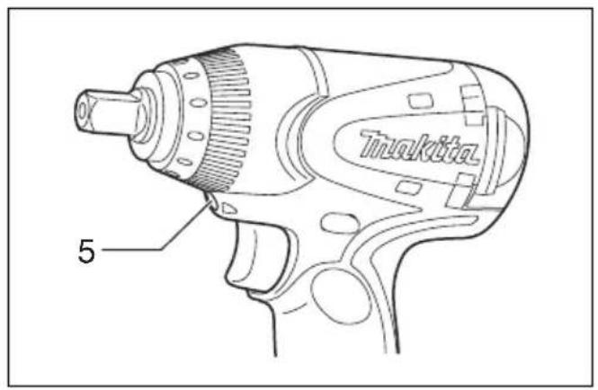
Reversing switch action (Fig. 4)
This tool has a reversing switch to change the direction of rotation. Depress the reversing switch lever from the A side for clockwise rotation or from the B side for counterclockwise rotation.
When the switch lever is in the neutral position, the switch trigger cannot be pulled.
CAUTION:
- Always check the direction of rotation before operation.
- Use the reversing switch only after the tool comes to a complete stop. Changing the direction of rotation before the tool stops may damage the tool.
- When not operating the tool, always set the reversing switch lever to the neutral position.
ASSEMBLY
CAUTION:
- Always be sure that the tool is switched off and the battery cartridge is removed before carrying out any work on the tool.
Selecting correct socket
Always use the correct size socket for bolts and nuts. An incorrect size socket will result in inaccurate and inconsistent fastening torque and/or damage to the bolt or nut.
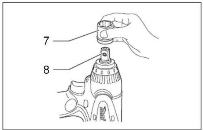
Installing or removing socket
- For socket without O-ring and pin (Fig. 5)
To install the socket, push it onto the anvil of the tool until it locks into place.
To remove the socket, simply pull it off.
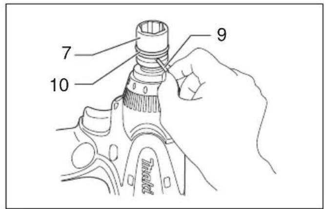
2. For socket with O-ring and pin (Fig. 6)
Move the O-ring out of the groove in the socket and remove the pin from the socket. Fit the socket onto the anvil of the tool so that the hole in the socket is aligned with the hole in the anvil. Insert the pin through the hole in the socket and anvil. Then return the O-ring to the original position in the socket groove to retain the pin. To remove the socket, follow the installation procedures in reverse.
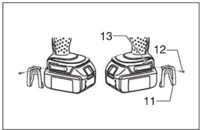
Hook (Fig. 7)
The hook is convenient for temporarily hanging the tool. This can be installed on either side of the tool.
To install the hook, insert it into a groove in the tool housing on either side and then secure it with a screw. To remove, loosen the screw and then take it out.
OPERATION
CAUTION:
- Always insert the battery cartridge all the way until it locks in place. If you can see the red part on the upper side of the button, it is not locked completely. Insert it fully until the red part cannot be seen. If not, it may accidentally fall out of the tool, causing injury to you or someone around you.
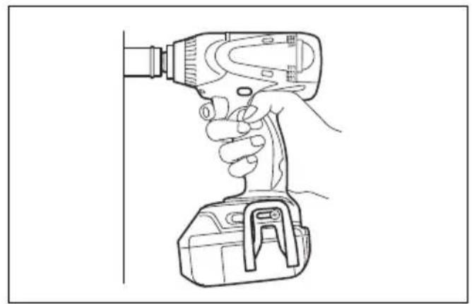
Hold the tool firmly and place the socket over the bolt or nut. Turn the tool on and fasten for the proper fastening time. (Fig. 8)
The proper fastening torque may differ depending upon the kind or size of the bolt, the material of the workpiece to be fastened, etc. The relation between fastening torque and fastening time is shown in the figures. (Fig. 9 & 10)
NOTE:
- Hold the tool pointed straight at the bolt or nut.
- Excessive fastening torque may damage the bolt/nut or socket. Before starting your job, always perform a test operation to determine the proper fastening time for your bolt or nut.
- If the tool is operated continuously until the battery cartridge has discharged, allow the tool to rest for 15 minutes before proceeding with a fresh battery cartridge.
The fastening torque is affected by a wide variety of factors including the following. After fastening, always check the torque with a torque wrench.
-
When the battery cartridge is discharged almost completely, voltage will drop and the fastening torque will be reduced.
-
Socket
-
Failure to use the correct size socket will cause a reduction in the fastening torque.
-
A worn socket (wear on the hex end or square end) will cause a reduction in the fastening torque.
-
Bolt
-
Even though the torque coefficient and the class of bolt are the same, the proper fastening torque will differ according to the diameter of the bolt.
-
Even though the diameters of bolts are the same, the proper fastening torque will differ according to the torque coefficient, the class of bolt and the bolt length.
-
The use of the universal joint or the extension bar somewhat reduces the fastening force of the impact wrench. Compensate by fastening for a longer period of time.
- The manner of holding the tool or the material of driving position to be fastened will affect the torque.
- Operating the tool at low speed will cause a reduction in the fastening torque.
MAINTENANCE
CAUTION:
- Always be sure that the tool is switched off and the battery cartridge is removed before attempting to perform inspection or maintenance.
Replacing carbon brushes
Replace when they wear down to the limit mark. Keep the carbon brushes clean and free to slip in the holders. Both carbon brushes should be replaced at the same time. Use only identical carbon brushes. (Fig. 11)
Use a screwdriver to remove two screws then remove the rear cover. (Fig. 12)
Raise the arm part of the spring and then place it in the recessed part of the housing with a slotted bit screw-driver of slender shaft or the like. (Fig. 13)
Use pliers to remove the carbon brush caps of the carbon brushes. Take out the worn carbon brushes, insert the new ones and replace the carbon brush caps in reverse. (Fig. 14 & 15)
Make sure that the carbon brush cap have fit into the holes in brush holders securely.
Reinstall the rear cover and tighten two screws securely.
To maintain product SAFETY and RELIABILITY, repairs, any other maintenance or adjustment should be performed by Makita Authorized Service Centers, always using Makita replacement parts.
ACCESSORIES
CAUTION:
- These accessories or attachments are recommended for use with your Makita tool specified in this manual. The use of any other accessories or attachments might present a risk of injury to persons. Only use accessory or attachment for its stated purpose.
If you need any assistance for more details regarding these accessories, ask your local Makita service center.
- Sockets
- Extension bar
- Universal joint
- Bit adapter
- Various type of Makita genuine batteries and chargers
Descriptif
VEILIGHEIDSVOORSCHRIFTEN VOOR ACCU
EC-DECLARATION OF CONFORMITY
We declare under our sole responsibility that this product is in compliance with the following standards of standardized documents,
EN60745, EN55014
in accordance with Council Directives, 89/336/EEC and 98/37/EC.
FRANÇAISE
DÉCLARATION DE CONFORMITÉ CE
Michigan Drive, Tongwell, Milton Keynes,
Bucks MK15 8JD, ENGLAND
Responsible manufacturer: Produttore responsabile:
EU-DEKLARATION OM KONFORMITET
Michigan Drive, Tongwell, Milton Keynes,
Bucks MK15 8JD, ENGLAND
Fabricante responsável: Ansvarlig produsent:
For European countries only
Noise and Vibration of Model BTW250
The typical A-weighted noise levels are
sound pressure level: 93 dB (A)
sound power level: 104 dB (A)
Uncertainty is 3 dB (A).
- Wear ear protection. -
The typical weighted root mean square acceleration value is 9 m/s^2 .
These values have been obtained according to EN60745.
FRANÇAISE
For European countries only
Noise and Vibration of Model BTW251
The typical A-weighted noise levels are
sound pressure level: 94 dB (A)
sound power level: 105 dB (A)
Uncertainty is 3 dB (A).
- Wear ear protection. -
The typical weighted root mean square acceleration value is 8.5 m/s^2 .
These values have been obtained according to EN60745.