G42 - Soundbar KLIPSCH - Free user manual and instructions
Find the device manual for free G42 KLIPSCH in PDF.
| Product Type | Soundbar |
| Brand | Klipsch |
| Model | G42 |
| Category | Soundbar |
| Built-in Channels | 3 (left, right, center) |
| Speaker Type | Passive (requires external amplifier) |
| Base included | Tempered glass |
| Wall mounting | Yes (keyhole slots) |
| Connection | Binding posts, speaker wire 16 gauge minimum |
| Cleaning | Dry cloth only |
| Safety | Do not expose to water or moisture; do not block ventilation openings |
| Warranty | 5 years (USA and Canada) |
| Included accessories | Tempered glass base, screws, adhesive tape, mounting template |
| Recommended use | Home theater, TV audio |
| Placement | On base or wall mount, near the screen |
| Power supply | None (passive) |
Frequently Asked Questions - G42 KLIPSCH
User questions about G42 KLIPSCH
0 question about this device. Answer the ones you know or ask your own.
Ask a new question about this device
Download the instructions for your Soundbar in PDF format for free! Find your manual G42 - KLIPSCH and take your electronic device back in hand. On this page are published all the documents necessary for the use of your device. G42 by KLIPSCH.
USER MANUAL G42 KLIPSCH
- READ these instructions.
- KEEP these instructions.
- HEED all warnings
- FOLLOW all instructions.
- DO NOT use this apparatus near water.
- CLEAN ONLY with dry cloth.
- DO NOT block any ventilation openings. Install in accordance with the manufacturer's instructions.
- Do not install near any heat sources such as radiators, heat registers, stoves, or other apparatus (including amplifiers) that produce heat.
- ONLY USE attachments/accessories specified by the manufacturer.
- USE only with a cart, stand, tripod, bracket, or table specified by the manufacturer, or sold with the apparatus. When a cart is used, use caution when moving the cart/ apparatus combination to avoid injury from tip over.
- DO NOT expose this apparatus to dripping or splashing and ensure that no objects filled with liquids, such as vases, are placed on the apparatus.

The exclamation point, within an equilateral triangle, is intended to alert the user to the presence of important operating and maintenance (servicing) instructions in the literature accompanying the product.

The lightning flash with arrowhead symbol within an equilateral triangle, is intended to alert the user to the presence of uninsulated "dangerous voltage" within the product's enclosure that may be of sufficient magnitude to constitute a risk of electrical shock to persons.
WARNING: To reduce the risk of fire or electrical shock, do not expose this apparatus to rain or moisture.
WARNING: No naked flame sources - such as candles - should be placed on the product.

CaUtiOn
RISK OF ELECTRIC SHOCK. DO NOT OPEN.

WARNING: Do Not Open! Risk of Electrical Shock. Voltages in this equipment are hazardous to life. No user-serviceable parts inside. Refer all servicing to qualified service personnel.
ThanKyOU
Thank you for your purchase of the Klipsch Gallery Series speakers! Each speaker blends versatile, superior styling with legendary Klipsch lifelike sound for seamless integration into any décor. The G-12, G-16 and G-28 speakers are designed to operate vertically or horizontally as left, center, right or surround speakers while the G-42 soundbar combines the three front channels in one aesthetic cabinet. Each model comes with a high quality, elegant, tempered glass base for stand, table or bookshelf placement and keyhole mounts for on-wall placement.
prODUCT rEGiStraTiOn
Register your product online at www.klipsch.com/register
- Klipsch will keep you up-to-date on new products and promotions
- Your personal information will never be resold
- This registration information is not used for warranty purposes. Please retain your receipt for warranty claims.
rROOM placEMEnT
Before You Start — Some Klipsch speakers have feet and other accessories that may need to be installed prior to use.
Left and Right Main Channel Speakers — For the most spacious sound Klipsch suggests placing the G-12, G-16 or G-28 front left/right speakers six to 15 feet (2 to 4.5m ) apart with the listening position about 1 to 1.5 times the distance separating the speakers. Excellent sound can still be achieved by placing/wall-mounting these speakers close to both sides of your TV if that is more aesthetically pleasing.
Center Channel Speakers — Speakers used as center channel speakers are designed to place dialogue and primary sounds so that they appear to come from the video screen. These speakers should therefore be placed/
wall-mounted horizontally, as close to the screen as possible, preferably at least 1" directly below the screen. The G-42 three-channel soundbar should also be placed/wall-mounted this way.
Rear Surround Channel Speakers — Speakers used as surround speakers should be placed approximately 2 feet above the listening position. Typically this will be about 5-7 feet above the floor. The surrounds should be placed on the walls directly adjacent to the listening position. Another option would be on the wall behind the listening position. The final surround speaker placement depends on your room's characteristics.
SpEaKER/SOUnDBar pEDESTal inSTallaTiOn
If you place your G-12,G-16,G-28 speakers or G-42 soundbar on a stand, table, etc. (vs. mounting on the wall), you will need to attach the provided tempered glass pedestals with the included screws.
Before you attach a pedestal, have the speaker wire that will attach to that speaker available since attaching the pedestal and connecting the speaker wire to a speaker are done at the same time (see "Connecting" section for proper wire connection).
The G-12, G-16 and G-28 speakers can be attached vertically or horizontally onto their pedestals and, therefore, have threaded inserts in two different positions on the rear of these speakers. The G-48 Soundbar can only be attached horizontally to its pedestal. Attach the pedestal as follows:
- Insert speaker wires (one set for G-12, G-16 and G-28 and three sets, left, right and center channel for G-42 soundbar) inside hole in pedestal back and pull through pedestal top (See Diagram 1).
- Position speaker/soundbar on ridge on pedestal top, lining up the holes in the top with the threaded inserts on the speaker (the G-12 has just one insert when in horizontal position and it should lineup with left hole on pedestal top).
- Using a Phillips screwdriver, screw the screws partially into the speaker inserts, without tightening them.
- If vertical mounting, attach speaker wires (see "Diagram 1"), adjust wires to fit in recessed area around terminals and tighten Phillips screws on pedestal. If horizontal mounting, route speaker wire from the rear center of speaker through channel(s) to the speaker terminals, attach speaker wires in same manner as vertical mounting, then tighten Phillips screws on pedestal. With the G-42 soundbar, use both channels to route all three sets of wires to the speaker terminals. (Note: using speaker wire larger than 18 gauge may not allow wire(s) to completely fit in channels). If needed, use the included adhesive strip to hold excess wire in place.
SpEaKER/S0UnDBar On-Wall inSTallaTiOn
If you mount your G-12,G-16,G-28 speakers or G-42 Soundbar on a wall, do not attach the pedestals. Determine a suitable location for each speaker to wallmount and complete all wiring to all speaker positions before mounting speakers to the wall. Do not ceiling-mount.
- If you have the G-28 or G-42, use included template and choose mount position for the speaker (horizontal or vertical). Pin template to wall, making sure it is level (when horizontally mounting) or plumb (when vertically mounting) and positioned correctly, centered with the TV's center points for example. Mark on wall the pilot hole locations through the template and remove template. If you have the G-12 or G-16, mark on wall 2 pilot hole points 9.26" apart for the G-12 or 13.25" apart for the G-16 (make sure the points are lined up so that the speaker hangs straight up and down vertically or level horizontally). For all speakers, Leave a minimum of one inch space between speaker cabinet and TV. Keep in mind that, when mounted, the speaker will "lock" into position 5/16" up, down, left or right of where the pilot holes are drilled.
- Pre-drill pilot holes in marked locations. If drilling into a wall stud (ideal) it is recommended to use #10 mounting screws (not included) to mount the speaker bracket (G-28 and G-42) or the speaker itself (G-12 and G-16). If there is no stud where a pilot hole is located, install wall anchors (not included) into the pilot holes to hold the bracket or speaker instead. Wall anchors should be rated to at least 6 pounds (G-12 and G-16) or 12 pounds (G-28 and G-42).
- If vertical wall-mounting, feed speaker wire into speaker bottom area and attach each wire to appropriate screw-terminal binding post (See Diagram 1). If horizontal wall-mounting, feed speaker wire to channel(s) that start on the back center part of the speaker, then continue running wire through the channel(s) and attach each wire to the appropriate screw-terminal binding post the same as if vertical mounting. (Note: using speaker wire larger than 18 gauge may not allow wire(s) to completely fit in channels). If needed, stick the included adhesive strip on a point over the channel to hold the wires in place in the channel (See Diagram 2).
- Gently push the speaker onto the two tabs on the mounted bracket through its keyholes (G-28 and G-42) or onto the two screws in the wall (G-12 and G-16) and push 5/16" up, down, right or left to lock into position.
COnnECTinG
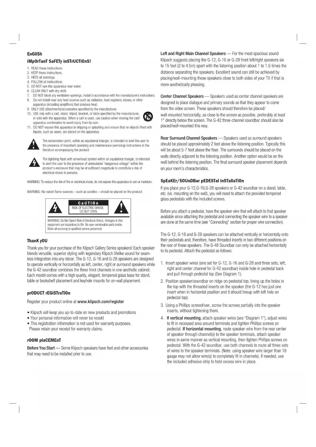
G-12,G-16,G-28 Connection - Using 16-gauge or larger speaker wire, connect the RED "positive" (+) terminal of the LEFT speaker to the RED "positive" (+) terminal of your amplifier's LEFT channel. Connect the BLACK "negative" (-) terminal of the left speaker to the BLACK "negative" (-) terminal of your amplifier's left channel. Repeat this procedure for connecting all remaining speakers to the appropriate amplifier channels.
G-42 Soundbar Connection - Since this speaker contains the LEFT, RIGHT and CENTER channels, connect each one of these channels from your amplifier as above to the designated "Left", "Right" and "Center" terminals on the G-42.
Make sure that no bare wires from any of the connections touch each other or any other terminals as this could cause a short and damage your equipment.
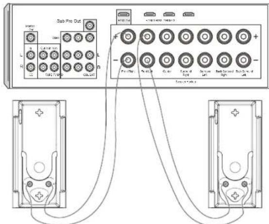
DiaGram 1
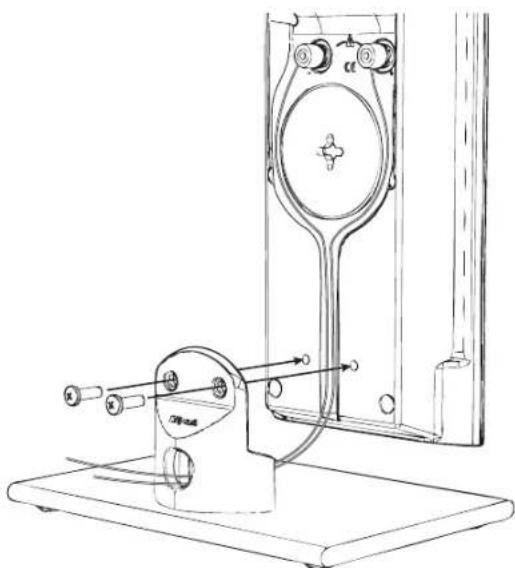
DiaGram 2
Warranty - U.S. and Canada
Klipsch Group, Inc. (KGI) warrants to the original retail purchaser that this product is to be free from defective materials and workmanship for a period of five (5) years from the date of purchase, if it is properly used and maintained. If this product proves defective in either material or workmanship, KGI, at its option, will (a) repair the product, or (b) replace the product, at no charge for parts or labor. If the product model is no longer available and cannot be repaired effectively or replaced with an identical model, KGI at its sole option may replace the unit with a current model of equal or greater value. In some cases, modification to the mounting surface may be required where a new model is substituted. KGI assumes no responsibility or liability for such modification. To obtain a repair or replacement under the terms of this warranty, please return to dealer first, if possible, and they will direct you accordingly for repairs or replacement. You will be required to submit a copy of the original receipt.
Limitations:
- This limited warranty does not cover failure of the product resulting from improper installation, misuse, abuse, accident, neglect, mishandling, or wear from ordinary use or environmental deterioration.
- This limited warranty does not cover cosmetic damage, including paint damage, or consequential damage to other components or premises which may result for any reason from the failure of the product.
- This limited warranty is null and void for products not used in accordance with KGI's instructions.
- This limited warranty is null and void for products with altered or missing serial numbers and for products not purchased from an authorized dealer.
- This limited warranty terminates if you sell or otherwise transfer this product to another party.
THIS WARRANTY GIVES YOU SPECIFIC LEGAL RIGHTS, AND YOU MAY ALSO HAVE OTHER RIGHTS WHICH VARY FROM STATE TO STATE, JURISDICTION TO JURISDICTION OR COUNTRY TO COUNTRY. KGI'S RESPONSIBILITY FOR MALFUNCTIONS AND DEFECTS IN HARDWARE IS LIMITED TO REPLACEMENT OR REPAIR AS SET FORTH IN THIS WARRANTY STATEMENT. FOR CANADIAN CUSTOMERS, KGI DISCLAIMS ALL OTHER WARRANTYIES AND CONDITIONS, EXPRESS OR IMPLIED, STATUTORY OR OTHERWISE, FOR THE PRODUCT. FOR U.S. CUSTOMERS, ALL EXPRESS AND IMPLIED WARRANTYES FOR THE PRODUCT, INCLUDING BUT NOT LIMITED TO ANY IMPLIED WARRANTYES OF MERCHANTABILITY AND FITNESS FOR A PARTICULAR PURPOSE ARE LIMITED IN TIME TO THE TERM OF THIS WARRANTY. SOME STATES, JURISDICTIONS OR COUNTRIES DO NOT ALLOW THE EXCLUSION OF CERTAIN IMPLIED WARRANTYES OR CONDITIONS, OR LIMITATIONS ON HOW LONG AN IMPLIED WARRANTY OR CONDITIONS LASTS, SO THIS LIMITATION MAY NOT APPLY TO YOU. KGI DOES NOT ACCEPT LIABILITY FOR SPECIAL, INDIRECT, CONSEQUENTIAL OR INCIDENTIAL DAMAGES, INCLUDING WITHOUT LIMITATION, ANY LIABILITY FOR THIRD PARTY CLAIMS AGAINST YOU FOR DAMAGES OR FOR PRODUCTS NOT BEING AVAILABLE FOR USE. THE MAXIMUM LIABILITY FOR WHICH KGI MAY BE RESPONSIBLE WILL BE NO MORE THAN THE AMOUNT YOU PAID FOR THE PRODUCT THAT IS THE SUBJECT OF THE CLAIM. SOME STATES, JURISDICTIONS OR COUNTRIES DO NOT ALLOW THE EXCLUSION OR LIMITATION OF SPECIAL, INDIRECT, INCIDENTAL OR CONSEQUENTIAL DAMAGES, SO THE ABOVE LIMITATION OR EXCLUSION MAY NOT APPLY TO YOU.
Warranty OUTSIDE The U.S. and Canada
The Warranty on this product if it is sold to a consumer outside of the United States and Canada shall comply with applicable law. To obtain any applicable warranty service, please contact the dealer from which you purchased this product, or the distributor that supplied this product.
EU COMplianCE inFOrMaTiOn:
Eligible to bear the CE mark, Conforms to European Union Low Voltage Directive 2006/95/EC; Conforms to European Union EMC Directive 2004/108/EC.
WEEE nOticE
Note: This mark applies only to countries within the European Union (EU) and Norway.
This appliance is labeled in accordance with European Directive 2002/96/EC concerning waste electrical and electronic equipment (WEEE). This label indicates that this product should not be disposed of with household waste. It should be deposited at an appropriate facility to enable recovery and recycling.