
GW20853 - Thermostat Gewiss - Free user manual and instructions
Find the device manual for free GW20853 Gewiss in PDF.
| Product type | Electronic thermostat for Fan-Coil |
| Brand | Gewiss |
| Model | GW20853 |
| Supply voltage | 230 V ~ 50/60 Hz |
| Temperature setting range | +5°C to +30°C (mechanically limitable) |
| Reading accuracy | ± 1°C |
| Control type | Proportional band (amplitude 1°C) |
| Maximum temperature gradient | 1 K / 15 min |
| Protection degree | IP30 |
| Insulation class | Class II |
| Number of fan speeds | 3 (Low, Medium, High) |
| Fan output maximum current | 5(2) A ~ 250 V |
| Valve output maximum current | 5(2) A ~ 250 V |
| Total maximum current | 5(2) A ~ 250 V |
| Maximum conductor cross-section | 2.5 mm² |
| Operating temperature | 0°C to +50°C |
| Main functions | Heating/cooling, 3 fan modes (fixed, thermostatic, valve only) |
| Maintenance and cleaning | Clean with a dry cloth. Do not use solvents. |
| Safety | Cut off power before installation. Installation by qualified personnel. |
| Spare parts and reparability | Contact Gewiss after-sales service for any intervention. |
| General information | Compliant with standards HD 384 - IEC364. Weight and dimensions not communicated. |
Frequently Asked Questions - GW20853 Gewiss
User questions about GW20853 Gewiss
0 question about this device. Answer the ones you know or ask your own.
Ask a new question about this device
Download the instructions for your Thermostat in PDF format for free! Find your manual GW20853 - Gewiss and take your electronic device back in hand. On this page are published all the documents necessary for the use of your device. GW20853 by Gewiss.
USER MANUAL GW20853 Gewiss
TERMOSTATO ELETTRONICO PER FAN-COIL
ELECTRONIC THERMOSTAT FOR FAN-COIL
THERMOSTAT ÉLECTRONIQUE POUR FAN-COIL
TERMOSTATO ELECTRONICO PARA FAN-COIL
ELEKTRONISCHER THERMOSTAT FÜR FAN-COIL
C E
GW 20 853 - GW 21 853
Electronic thermostat for Fan-Coil
ATTENTION - IMPORTANT
- Congratulations for having choosing a Gewiss product. Gewiss products are constructed with careful attention to detail, using only high quality materials. Gewiss products assure you of peak performance over time.
- Carefully read the following instructions since they contain important information on installing and operating the product. The installer should give these instructions to the final user and ask him to read the contents.
- System programming products must be installed in conformity with the provisions of HD 384 - OEC364 regulations for devices for household or similar use in non-dusty rooms or where special protection against water penetration is not required.
- On case of failure and/or malfunction, contact an authorized technician or GEWÖSS SAT technical assistance service.
INNUX
page
GUNURAL PRONUÉT NUSERIPION
-yunctions 14
- INSTALLATION INSTRUMENTS
- location advice 15
-x electrical connections 16
- OPÜRATING INSTRUÉTIONS
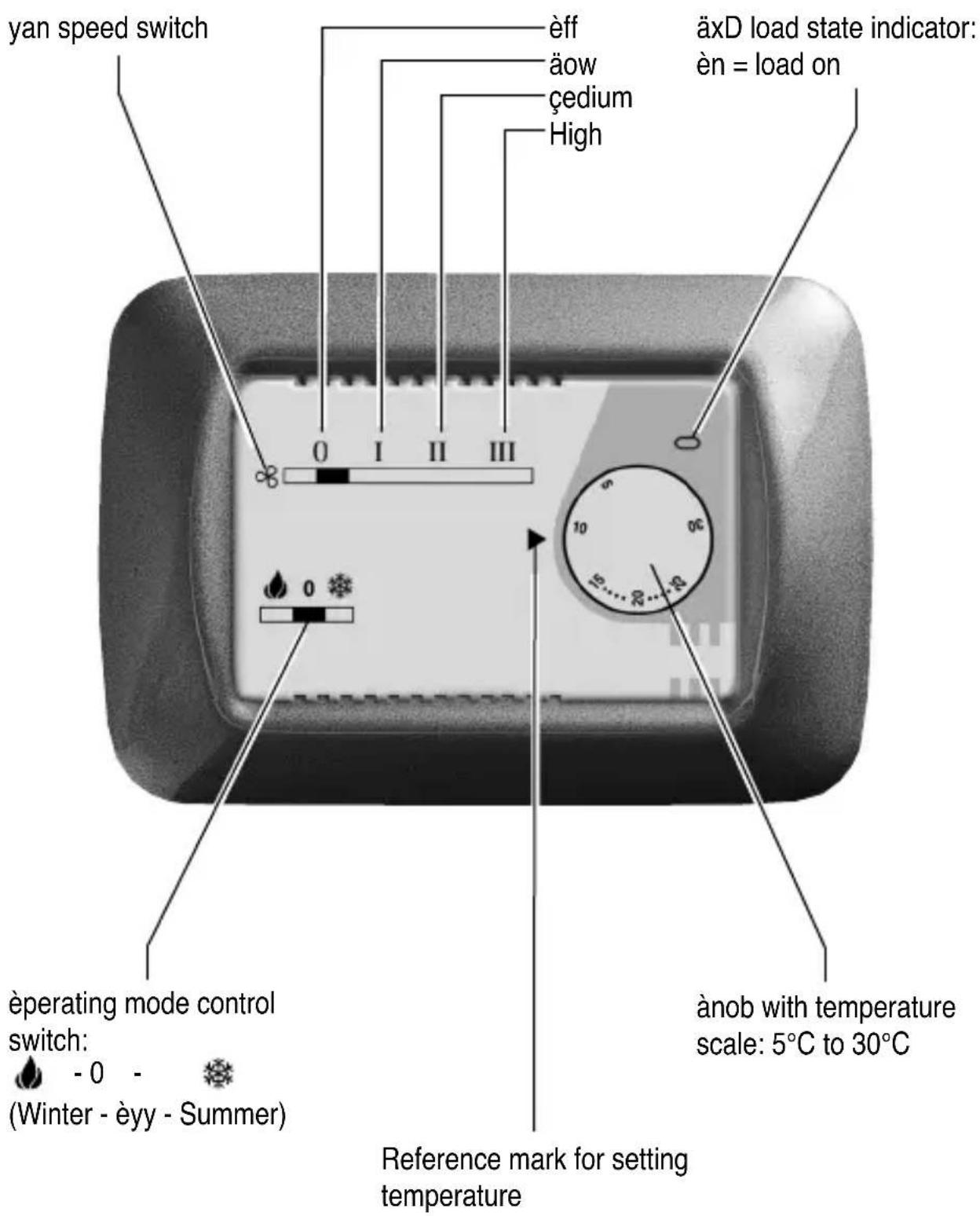
-Commands and signals 18
- operating mode 19
FUNÉTIONS

OPÜRATING NATA
- operating mode: thermostat-controlled solenoid valve and continuous fan operation, thermostat-controlled solenoid valve and fan operation, thermostat-controlled fan operation only and solenoid valve not connected
- Temperature setting block: mechanical with "range disk" (supplied)
- Ondicator lights: load on/off aED

TÜÉUNIEAL NATA
Supply voltage: 230V 50÷ 60Hz
- Disconnection and appliance type: 1 B / Electronic
- output type by control type:
- continuous fan operation polarized single-pole switch 5(2)A / 250 V~
- solenoid valve (thermostat-controlled) polarized single-pole
ee/eFF relay 5(2)A / 250 V~ -
fan + solenoid valve relay + switch (thermostat-controlled) maximum total load 5(2)A / 250 V~
-
maxium terminal wire section: 2,5mm
- Onsulation type: Class ÖÖ
-êrotection class:Öe 30 - éollution: éormal
- Temperature control range: from +5ircC to +30ircC (limitable)
- Thermal gradient: max 1 à/15 min.
- Control type: proportional band (width 1ircC )
- Reading accuracy: ± 1°C
- operating temperature range: 0ircC to +50ircC
- Reference standards for CE certification:
EcC Eé55014-1 Eé55014-2 Eé61000-3-2 Eé61000-3-3
äVD Eé60730-1 Eé60730-2-9
(Directive 89/336/EEC - 7323/EEC)
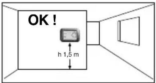
LOCATION ADVICE
OK

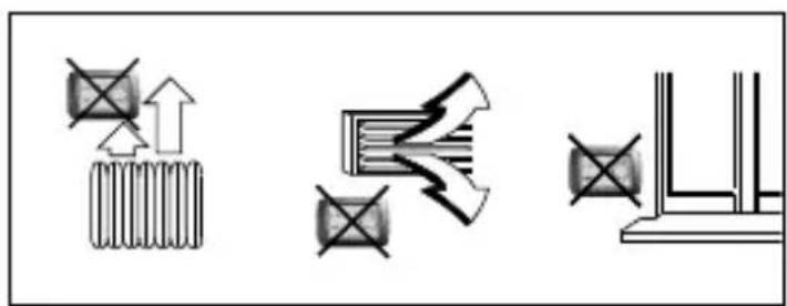
Recommendations on positioning:
Önstall the thermostat at a height of from 1.50 to 1.70m from the floor, far away from sources of heat, air ducts, doors or windows.
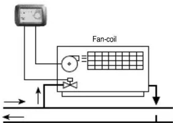
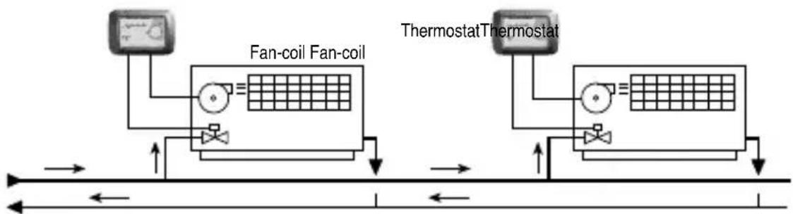
Example of installation with thermostat controlling the fan and solenoid valve.
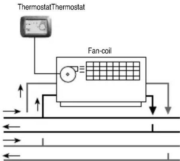
Example of installation with thermostat controlling only the fan.
N.B.: The examples shown in the following documentation are for illustration purposes only.
ELECTRICAL CONNECTIONS
Important: electrical wiring installation of the devices and appliances should be carried out by qualified technicians in accordance with the regulations and laws in force. The manufacturer will not assume any responsibility for the use of products that must comply with special environmental and/or installation regulations; this obligation is the responsibility of and to the charge of the installer.
Warning: before installing the product, disconnect the power supply.
Important: the thermostat control outputs are polarized; pay close attention to aine and eneutral connections.
Wiring: as indicated in the figure.
Disconnect the power supply (main breaker).
Connect the supply line to terminals nirc2 (eeutral) and nirc3 (aine).
Connect the fluid interception solenoid valve to terminal nirc 4.
Based on the type of installation, connect the wires for speed control coming from the fan to terminals n° 5-6-7: terminal n° 5 - fan "High"
The setting wire must always be connected to terminal nirc3 or terminal nirc4 .
Setting the Fan-coil control mode
N.B.: the solenoid valve is always thermostat controlled.
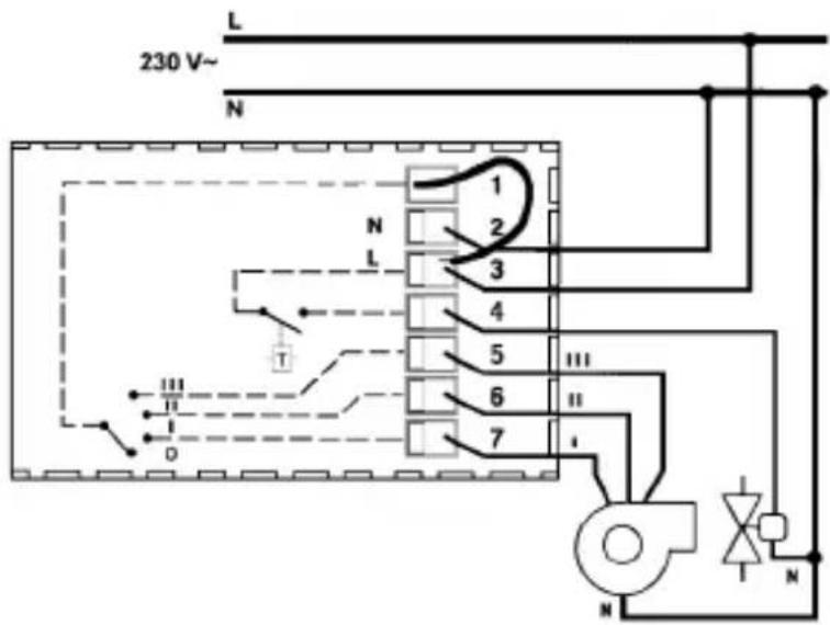
a) - Thermostat-controlled fan operation
Connect the wire that comes out of the first hole of the thermostat terminal board (hole 1) to terminal nirc4 .
Wiring diagram for solenoid valve control and fan control with thermostat-controlled operation
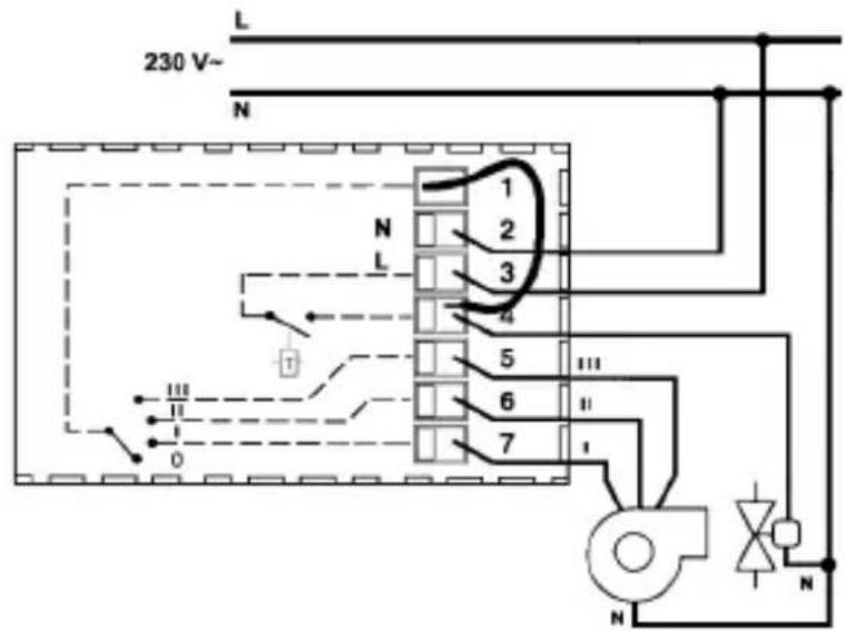
b) - Continuous fan operation
Connect the wire that comes out of the first hole of the thermostat terminal board (hole 1) to terminal nirc3 .
Wiring diagram for solenoid valve control and fan control with continuous fan operation
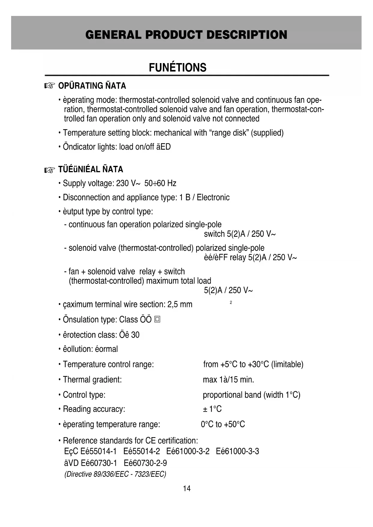
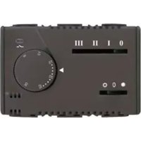
ÉOMMANNS ANN SIGNALS
OPERATING PMODE
Based on the devices connected (fan and/or solenoid valve) and the terminal (nirc3 or nirc4) to which the wire for the fan operating mode setting is connected, the thermostat can operate in the following modes:
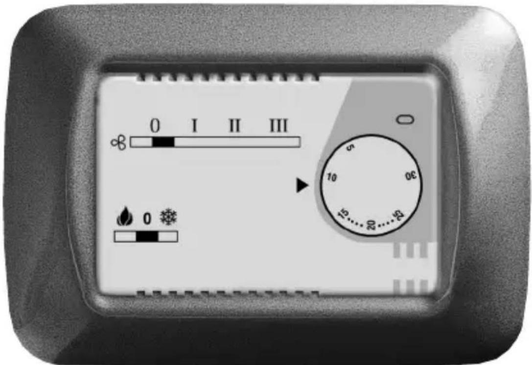
1) thermostat-controlled solenoid valve and continuous fan operation (fig. A)
2) thermostat-controlled solenoid valve and fan operation (fig. A)
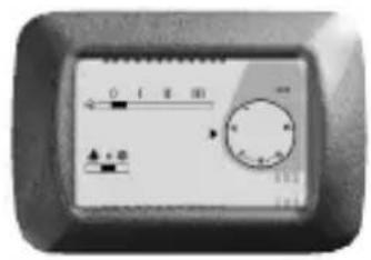
3) thermostat-controlled fan operation only and solenoid valve not connected (fig. B)
On all cases, 3 different fan speeds can be selected by a switch on the front panel. Heating or cooling mode can also be selected by a switch on the front panel.
Fig. A
Example of thermostat installation with thermostat-controlled solenoid valve and fan control (continuous or thermostat-controlled)
Fig. B
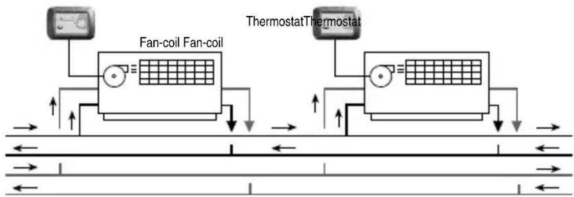
Example of thermostat installation with fan control only (continuous or thermostat-controlled)
The thermostat operates with proportional temperature control, within a 1ircC -band
width, as shown in the figure. Regulation is carried out by switching the load on and off for variable time intervals, depending on the difference between the temperature setpoint and the temperature reading.

Gew55
FRANÇAIS
LOGIQUE PD'APPLICATION

OK

Date of installation
Room in which installed
Installer's stamp and signature


- TERMOSTATO ELETTRONICO PER FAN-COIL
- ATTENTION - IMPORTANT
- INNUX
- GUNURAL PRONUÉT NUSERIPION
- - INSTALLATION INSTRUMENTS
- - OPÜRATING INSTRUÉTIONS
- FUNÉTIONS
- OPÜRATING NATA
- TÜÉUNIEAL NATA
- LOCATION ADVICE
- Recommendations on positioning:
- ELECTRICAL CONNECTIONS
- Setting the Fan-coil control mode
- a) - Thermostat-controlled fan operation
- b) - Continuous fan operation
- ÉOMMANNS ANN SIGNALS
- OPERATING PMODE
- Gew55
- FRANÇAIS
- LOGIQUE PD'APPLICATION
Brand : Gewiss
Model : GW20853
Category : Thermostat