
GW14793 - Thermostat Gewiss - Free user manual and instructions
Find the device manual for free GW14793 Gewiss in PDF.

| Product Type | Wall-mounted EIB thermostat for thermal regulation |
| Brand | Gewiss |
| Model | GW14793 |
| Dimensions (W x H x D) | 85 x 95 x 23 mm |
| Weight | Approximately 100 g (estimate) |
| Power Supply | KNX/EIB bus 29 V DC SELV + rechargeable battery ML1220 3 V (clock backup) |
| Bus consumption | 5 mA |
| Display | Backlit LCD with timeout |
| Control elements | 5 front buttons, 1 physical address programming button |
| Temperature sensor | Integrated NTC, resolution 0.1 °C, accuracy ±0.5 °C at 20 °C |
| Temperature display range | 0 to +45 °C |
| Setpoint ranges | Frost protection: +2 to +7 °C; High temperature protection: +30 to +40 °C; Other: +5 to +40 °C |
| Operating modes | Off, Economy, Pre-comfort, Comfort |
| Operating types | Heating and cooling |
| Control algorithms | 2-point (on/off) or proportional (PWM or continuous) |
| Fan coil management | Yes, for 2 or 4 pipe installations, speed control (auto/manual) |
| Configuration | Via ETS software (physical address, communication objects) |
| Additional functions | Scenarios (8), temporary override, remote control, slave/standalone mode |
| Backup power | Rechargeable battery ML1220 (36 h backup for clock) |
| Operating temperature | -5 to +45 °C |
| Relative humidity | Max 93% (non-condensing) |
| Protection rating | IP20 |
| Maintenance and cleaning | Clean with a dry cloth. Do not use abrasive products or solvents. |
| Safety | Installation by qualified personnel according to IEC 64-8. Observe safety distances (4 mm between bus and mains cables). |
| Spare parts and repairability | Replaceable rechargeable battery ML1220. No other spare parts specified. |
| General information | Wall thermostat for KNX/EIB system. Used in combination with a master chronothermostat. Ensures thermal comfort and energy savings. |
Frequently Asked Questions - GW14793 Gewiss
User questions about GW14793 Gewiss
0 question about this device. Answer the ones you know or ask your own.
Ask a new question about this device
Download the instructions for your Thermostat in PDF format for free! Find your manual GW14793 - Gewiss and take your electronic device back in hand. On this page are published all the documents necessary for the use of your device. GW14793 by Gewiss.
USER MANUAL GW14793 Gewiss
GW 10 793 GW 14 793
pag.
AVVERTENZE GENERALI
natural_image
Technical line drawing of a device rear panel with internal compartments and connectors (no text or symbols)natural_image
Simple line drawing of a rectangular object with a central explosion-like symbol and the label 'SET' at the bottom (no text or symbols on the object itself)natural_image
Simple diagram with a temperature symbol and a starburst icon, no text or labels present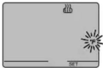
natural_image
Simple diagram with a gray rectangle, a white outline, and a black starburst symbol on the right (no text or labels)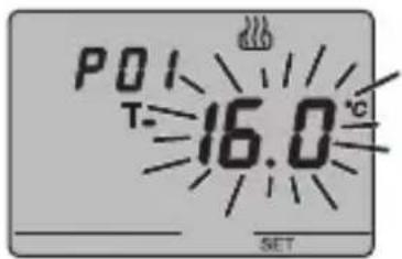

CONDIZIONAMENTO
NOTA 1
natural_image
Cross-sectional diagram of a device casing showing internal compartments and components (no text or labels)ISTRUZIONI D'IMPIEGO

ATTENZIONE
natural_image
Four-panel illustration showing a window, ceiling-mounted sensors, and sunlight rays interacting with a window (no text or symbols)natural_image
Diagram of a device interior showing internal components and a cable inserted into a housing (no text or labels)DATI TECNICI
Control elements and rear display 39
Position of the commands 40
Command description 41
Control mode 42
Operation mode 42
USER INSTRUCTIONS
Setting parameters 44
Temporary temperature forcing ....55
Reset and reinstatement of default settings ....55
Default parameters 56
Behaviour on the failure and reinstatement of the bus power supply .....57
Replacing the battery 58
Cleaning the thermostat ....59
INSTALLATION INSTRUCTIONS
Correct installation position 60
Assembly of the support base 60
Warnings for KNX/EIB installation 61
Electrical connections 62
Completing installation ....64
TECHNICAL DATA 65
GENERAL INFORMATION
Warning! The safety of this appliance is only guaranteed if all the instructions given here are followed scrupulously. These should be read thoroughly and kept in a safe place. The Chorus products must be installed in compliance with the requisites of standard CEI 64-8 for devices for domestic use and similar, in non-dusty atmospheres and where special protection against water penetration is not required.
The GEWISS sales organisation is at your disposal for clarifications and technical information.
Gewiss SpA reserves the right to make changes to the product described in this manual at any time and without giving any notice.
Pack content
n. 1 EIB wall thermostat
n.1 Support base
n. 1 Bus terminal
n. 1 Installation and user manual
Summary
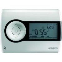
The EIB wall thermostat allows you to manage the temperature in the area it is installed in. The temperature is regulated by the KNX/EIB actuators which are managed by the Building Automation KNX/EIB bus and control the heating or air-conditioning elements, including the fan coils.
When combined with the EIB wall timer-thermostat (GW 10 791 - GW 14 791), from which it receives the operation type and mode via the bus, it is possible to create multi-zone thermal regulation systems.
The set point values used by the thermostat are those set via ETS and can be changed locally and via bus if these options were enabled during ETS configuration.
The thermostat comprises:
- 2 function types: heating and air conditioning;
- 4 operating modes: OFF, Economy, Precomfort and Comfort;
- 4 temperature settings for the heating function (Teconomy, Tprecomfort, Tcomfort, Tfrostprotect.)
- 4 temperature settings for the air-conditioning function (Teconomy, Tprecomfort, Tcomfort, Thigh_temperature_protection);
- 2 temperature control algorithms: at 2 points (command ON/OFF or 0% / 100% ) and proportional (PWM or continuous type control);
- fan coil control for 2 or 4 way system and speed control.
The thermostat is powered by the supplied bus line and is fitted with a timer backlit LCD display, 5 control buttons, an integrated sensor to detect the room temperature (the value of which is sent to the bus at a programmable frequency or following a temperature change of at least 0.5irc C, according to ETS settings), a rechargeable battery (included) to maintain the date and time on the display (when power is disconnected from the bus).
The device is configured by the ETS software to achieve one of the functions listed below:
Temperature control
- with 2 points, ON/OFF commands or 0% 100% commands;
• proportional control, with PMW commands or constant regulation (0% ÷ 100%).
Fan coil control
- fan coil speed control with ON/OFF selection controls or constant regulation (0% ÷ 100%);
- 2 or 4 way system control with ON/OFF commands or 0% / 100% commands.
GENERAL DESCRIPTION
Setting the operation mode
- from the bus with separate 1 bit objects (OFF, ECONOMY, PRECOMFORT, COMFORT);
• from the bus with 1 byte objects.
Temperature reading
- with integrated sensor or temperature probe;
- mixed with definition of the relative weight.
Temperature control in zones
- with operating mode received from the master device and using room set points;
- with set point value received from the master device and room temperature differential.
Scenes
• memorising and activating the 8 scenes (value 0..63).
Other functions
- setting of the (OFF, ECONOMY, PRECOMFORT, COMFORT) set point by the bus;
- setting the function type (heating/air conditioning) by the bus;
- transmission to the bus of the status information (mode, type), the temperature reading and current set point;
- management of status information sent from the controlled actuator;
- window status signal management to temporarily turn off the thermostat.
The device is installed on the wall using the supplied flange that can be fixed to the wall using dowels or screwed onto a round or square flush-mounted box.
GENERAL DESCRIPTION
Control elements and rear display
GENERAL DESCRIPTION
Position of the commands
The thermostat is fitted with a backlit LCD display and 5 control buttons which are always accessible.
GENERAL DESCRIPTION
Command description
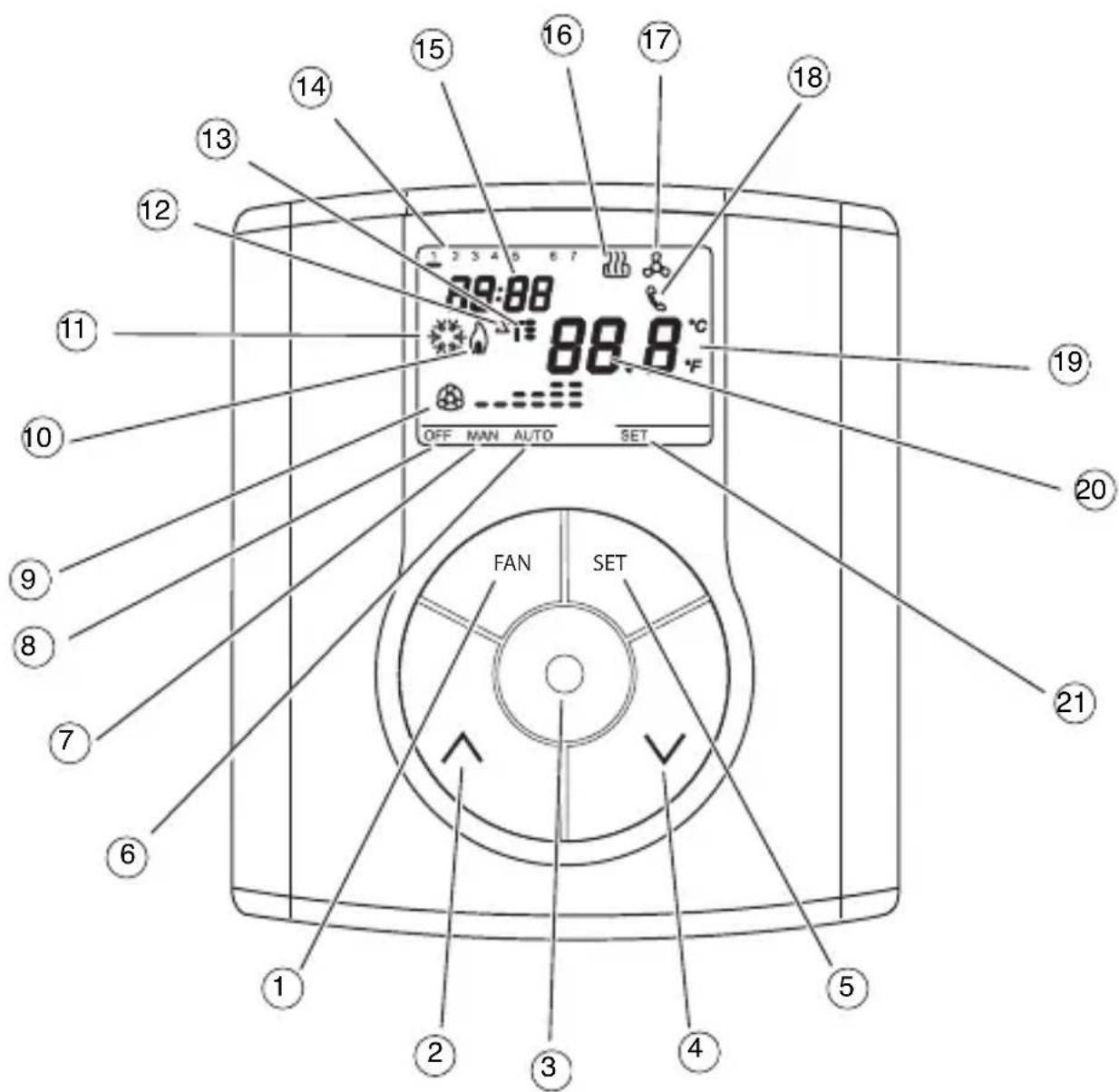
CONTROL BUTTONS Symbol Page
① Fan-coil speed regulation FAN 44
② Temperature regulation (+) / Select settings 54
③ Select operation mode / confirmation 42
④ Temperature regulation (-) / Select settings 54
⑤ Setting parameters SET 44
VDU SIGNALS
⑥ Auto operation mode for the connected fan coil AUTO
⑦ Manual operation mode for the connected fan coil MAN
⑧ Thermostat in operation mode OFF OFF
⑨ Operation mode fan coil ON
speed OFF 44
speed 1 --
speed 2 --
speed 3
⑩ Activation of heating 44
11 Activation of air-conditioning 44
⑫ Thermal differential △T
13 Temperature set-point – Operation mode T. T: T 42
14 Day of the week 46
⑮ Clock 46
16 Heating function 46
17 Air conditioning function 46
18 Activation by remote control
19 Temperature unit of measurement irc C / irc F 46
20 Ambient temperature measured
21 Setting parameters SET
Control mode
The thermostat can be set to 2 different control modes:
- Slave: operations depend on the device set as the Master (for example, the EIB GW 10 791 timer-thermostat), that sets the type, operation mode or set point for the thermostat according to ETS settings. In the first case (mode), the thermostat uses the set points set via ETS which can be changed locally and via bus if these options were enabled in ETS settings. It is possible to temporarily force the set temperature set-point (max variation ± 5 °C), whilst it is not possible to change the operation mode. The forced set-point will remain valid until the Master device sends a new operation mode. In the second case (set point), the thermostat uses the set point received from the Master device to which a local variation (max ± 5 °C) can always be applied.
- Stand alone: the thermostat operation type and mode are set locally. The operation status does not depend on any other device. In Stand-alone mode it is possible to vary the set-point at will and enable the thermostat to receive remote commands for mode settings (OFF/Economy/Precomfort/Comfort) and type (Heating/Air-conditioning) from other devices, such as for instance a button or the EIB GSM remote control unit GW 90 815.
Operation mode
The thermostat foresees 4 different operation modes:
• ECONOMY
- PRECOMFORT
• COMFORT
- OFF-FROSTPROTECT / HIGH TEMPERATURE PROTECTION
In the Stand Alone control mode use the key to switch from one mode to another. In Slave control mode, with Master operation mode settings, the key is not enabled since the operation mode is set by the device set as Master.
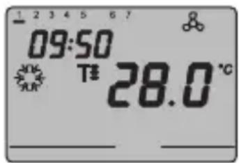
In the economy, precomfort and comfort function modes the thermostat permanently uses the corresponding temperature set-points.
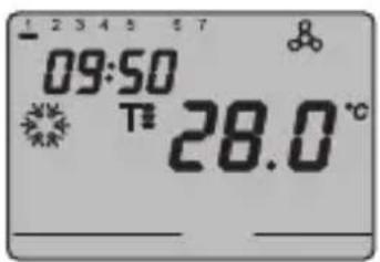
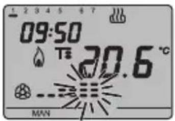
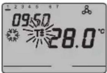
The current ambient temperature and the symbol, T-, T=, or appear on the screen.
GENERAL DESCRIPTION
MEANING OF T. T: T:
| Symbol | Heating Air conditioning | |||
| Set point | Operation mode | Set point | Operation mode | |
| T- | TECONOMY | Economy | TCOMFORT | Comfort |
| T= | TPRECOMFORT | Precomfort | TPRECOMFORT | Precomfort |
| T= | TCOMFORT | Comfort | TECONOMY | Economy |
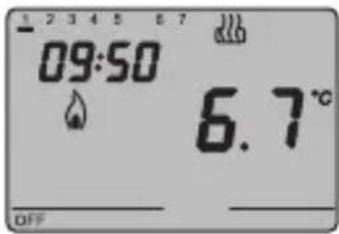
The frostprotect function is only enabled in heating function mode, when the thermal regulation system is OFF. In this case the thermostat uses the set frostprotect set-point re-starting the heating system only when the ambient temperature decreases below TFROSTPROTECT.
The message "OFF" and the measured ambient temperature are displayed on the VDU.
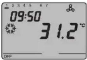
The high-temperature protection function is only enabled in air-conditioning mode, when the thermal regulation system is OFF.
In this case the thermostat uses the set high-temperature set-point
re-starting the air-conditioning system only when the ambient temperature exceeds the THIGH TEMPERATURE PROTECTION.
The message "OFF" and the measured ambient temperature are displayed on the VDU.
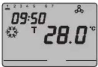
In Slave mode with Master set point settings, the key is disabled. The temperature and symbol T appear on the screen. The thermostat uses the set point received via bus from the Master device.
OPERATING INSTRUCTIONS
During operation, the activation of. the heating or air-conditioning functions are indicated as followed:
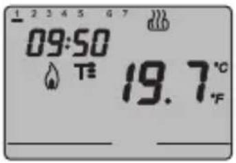
Heating
The symbol indicates that the activation command has been sent to the actuator which controls the boiler or the zone electrovalve. If the load notice has been sent via the ETS and the thermostat does not receive confirmation from the actuator that the same has been activated, the symbol starts to flash. Subsequently, the thermostat sends the activation command again, at one minute intervals, until it receives a positive response.
Air conditioning
The symbol indicates that the activation command has been sent to the actuator which controls the air-conditioner or the zone electrovalve. If the load notice has been sent via the ETS and the thermostat does not receive confirmation from the actuator that the same has been activated, the symbol starts to flash. Subsequently, the thermostat sends the activation command again, at one minute intervals, until it receives a positive response.
Operation with fan-coil control activated
The symbol appears on the display if the fan-coil control is activated in the parameter settings.
Press the FAN key repeatedly to adjust the fan-coil speed or set the AUTO mode option, where the fan-coil speed is automatically regulated according to the difference between the set-point set on the device and the current temperature. The fan coil speed indicator flashes when the fan is running.
Setting parameters
To set the thermostat parameters, press the SET key.
The word SET appears on the display and the symbol of the set operation type (heating or air-conditioning) starts to flash.
OPERATING INSTRUCTIONS
It is possible to set the following parameters:
| Operation type (heating/air conditioning) |
| Day of the week |
| Hours |
| Minutes |
| Temperature unit of measurement |
If local set point changes are enabled via ETS, the following parameters are also displayed and editable locally:
| Heating Air conditioning | ||
| P01heat - Set Point P01cond - Set Point | 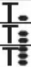 | |
| P02heat - Set Point P02cond - Set Point | ||
| P03heat - Set Point P03cond - Set Point | ||
| P04heat - Set Point TFROSTPROTECT | P04cond - Set Point THIGH TEMPERATURE PROTECTION | |
| P05heat - Control logic (displayed but disabled) | P05cond - Control logic (displayed but disabled) | |
if the control logic = proportional
| P06heat - Cycle time P06cond - Cycle time | |
| P07heat - Proportional regulation differential value | P07cond - Proportional regulation differential value |
| P08 - Minimum percentage value to send the command (displayed if the 1 byte command is selected via ETS) | |
if the control logic = 2 points
| P09heat - 2 point regulation diff. value | P09cond - 2 point regulation diff. value |
if the control logic = fan coil
| P10heat - Speed regulation diff. value 1 | P10cond - Speed regulation diff. value 1 |
| P11heat - Speed regulation diff. value 2 | P11cond - Speed regulation diff. value 2 |
| P12heat - Speed regulation diff. value 3 | P12cond - Speed regulation diff. value 3 |
if the devices is set as Slave with mode settings by ETS or autonomous with remote controls enabled
P13 Enabling/disabling of the Slave function
if Slave function = on or device set as Slave with Set Point settings by ETS
P14 - Set point variation interval for manual override
if Slave function = off
P15 - Enable remote control mode settings
OPERATING INSTRUCTIONS
To scroll the sequence, confirming the values displayed on the screen, press the key until you reach the parameter you want to change.
Press the SET key again to exit the parameter setting procedure or it will exit automatically after a 30" time-out.
It is necessary to perform both sequences to set the heating and air-conditioning parameters (in the second sequence it is possible to confirm the parameters which are the same, and just change the specific ones).
natural_image
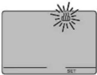
Simple line drawing of a rectangular object with a central explosion-like symbol and the label 'SET' at the bottom (no text or symbols on the object itself)Selecting heating/air conditioning
When the or symbol blinks it is possible to select the operating type using the keys
Press the Ⓞ key within 30 seconds to confirm the selection.
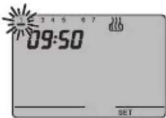
Setting the day of the week
When the day of week bar is blinking, select the current day using the keys.
(Monday=1, Tuesday=2 ... Sunday=7).
Press the key within 30 seconds to confirm the value set.
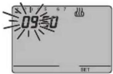
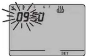
Setting the hour
When the hour figures blink, set the time using the keys ∧∨.
Press the key within 30 seconds to confirm the value set.
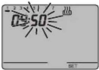
Setting the minutes
When the minutes figures blink, set the minutes using the keys ∧∨
Press the key within 30 seconds to confirm the value set.
OPERATING INSTRUCTIONS
natural_image
Simple diagram with a sunburst symbol and text 'SET' at the bottom, no readable text or labels present.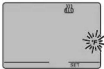
natural_image
Simple diagram with a flame icon and a 'SET' label, no readable text or symbols beyond the label.
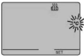
Setting the temperature unit of measurement
When the temperature symbol °C or °F starts to blink, select the temperature unit of measurement using the keys. Press the key within 30 seconds to confirm the value set.
P01heat - Set Point setting (heating)
The temperature value starts to blink when the symbol appears. Regulate the value (TECONOMY) using the V keys.
Press the key within 30 seconds to confirm the value set.

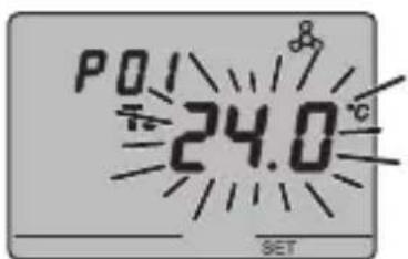
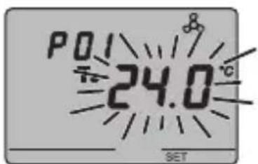
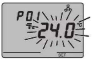
P01cond - Set Point Setting (air conditioning)
The temperature value starts to blink when the symbol appears. Regulate the value (TCOMFORT) using the keys.
Press the ⓔ key within 30 seconds to confirm the value set.
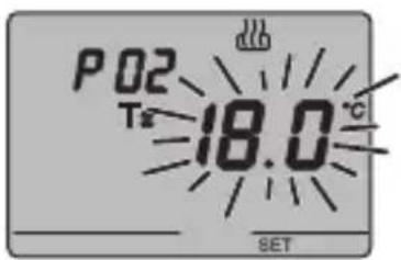
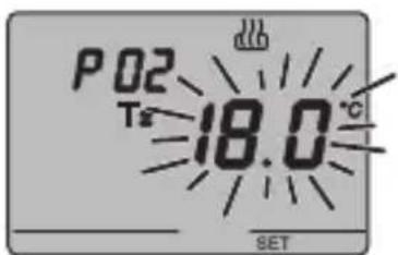
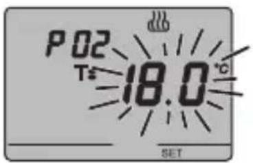
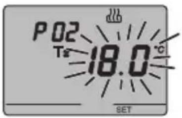
P02heat - Set Point setting (heating)
The temperature value starts to blink when the symbol appears. Regulate the (T PRECOMFORT) value using the keys.
Press the key within 30 seconds to confirm the value set.
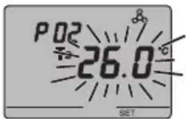
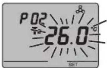
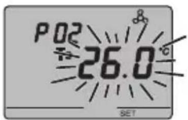
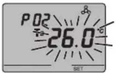
P02cond - Set Point setting (air conditioning)
The temperature value starts to blink when the T= symbol appears. Regulate the value(T PRECOMFORT) using the keys.
Press the key within 30 seconds to confirm the value set.
OPERATING INSTRUCTIONS
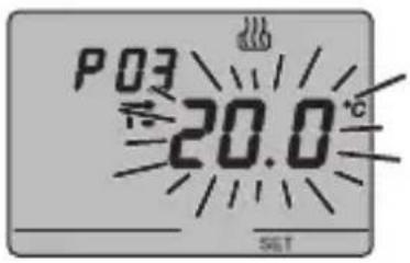
P03heat - Set Point setting (heating)
The temperature value starts to blink when the symbol appears. Regulate the value (TCOMFORT) using the keys.
Press the key within 30 seconds to confirm the value set.
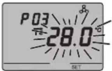
P03cond - Set Point (air conditioning) setting
The temperature value starts to blink when the symbol appears. Regulate the value (T ECONOMY) using the keys.
Press the key within 30 seconds to confirm the value set.
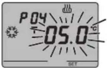
P04heat - Set frostprotect temperature value
The temperature value starts to blink when the symbol appears. Regulate the frostprotect temperature value using the keys.
Press the key within 30 seconds to confirm the value set.
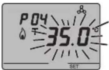
P04cond - Set high temperature protection value
The temperature value starts to blink when the symbol appears. Regulate the high temperature protection value using the buttons.
Press the key within 30 seconds to confirm the value set.
WARNING!
The set-point values have the following limits:
- HEATING
T FROSTPROTECT


- AIR CONDITIONING


MPERATURE PROTECTION
OPERATING INSTRUCTIONS
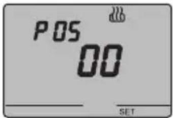
P05 - Control logic
When P05 appears on the screen, the thermal regulation system control logic is displayed.
(0 0 = 2 point control, 0 1 = proportional control, 0 2 = fan coil control)
The thermal regulation system control logic cannot be changed locally.
If the control is set to 2 points, go to point P09, if set to fan coil, go to point P10, if proportional, go to point P06.
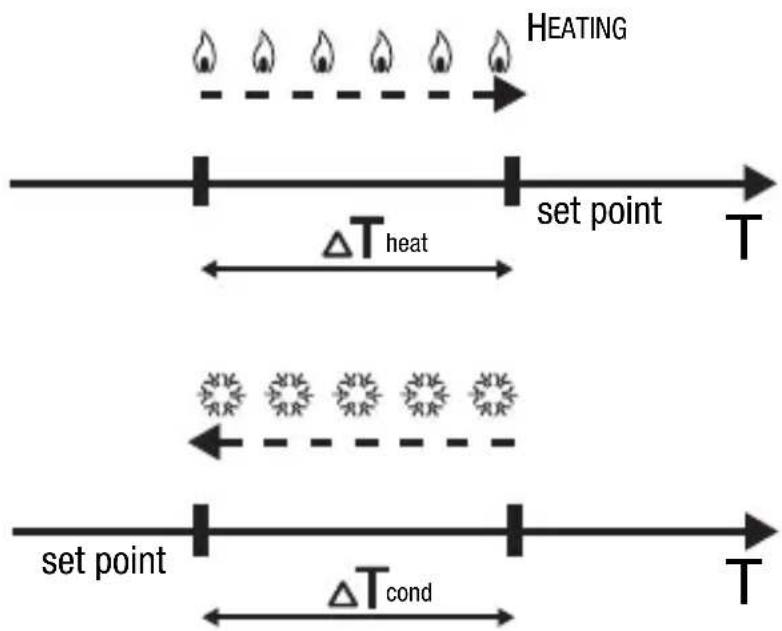
2 POINT CONTROL
The thermal regulation system is switched off when the ambient temperature is equal to the set point, and is switched back on when:
- the temperature is equal to or lower than the set point - ΔT heat for heating;
- the temperature is equal to or higher than the set point + ΔT cond for air-conditioning;
The diagrams below show the two function types.
flowchart
graph LR
    A["HEATING"] --> B["set point T"]
    B --> C["ΔT heat"]
    C --> D["set point T"]
    D --> E["ΔT cond"]
    E --> F["set point T"]
AIR CONDITIONING
To avoid continuous switchings, the thermostat will wait for up to 2 minutes before sending the activation command to the actuator that controls the thermal regulation system.
OPERATING INSTRUCTIONS
PROPORTIONAL CONTROL
At the end of each cycle time, the thermostat controls the ambient temperature and, based on the difference found with the set point, turns the boiler on or off (PWM) or sends a heating or cooling control value command (constant control).
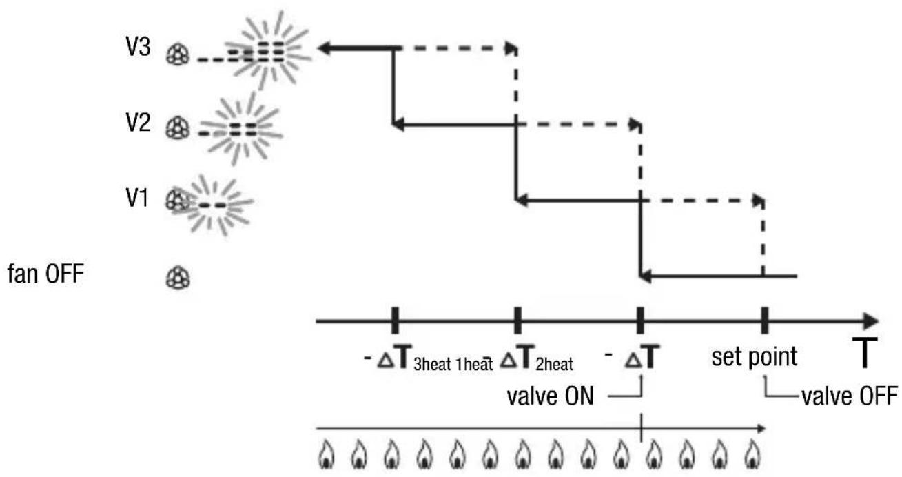
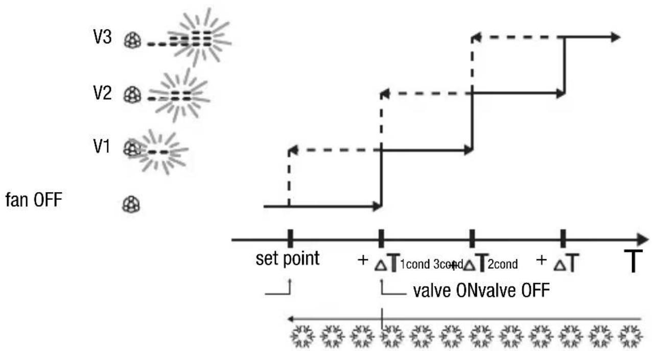
FAN COIL CONTROL
When the temperature reaches set point - ΔT1heat (in heating) or set point + ΔT1cond (in air conditioning), an ON or 100% value message is sent to open the valve and an ON message (speed control 3) or 1 byte value (constant control) to start speed V1. At set point - ΔT2heat (in heating) or set point + 2cond (in air conditioning) speed V2 is starts, at a set point - 3heat (in heating) or set point + 3cond (in air conditioning) speed V3 is started.
OPERATING INSTRUCTIONS
HEATING
flowchart
graph TD
    fanOFF["fan OFF"] --> V1["V1"]
    fanOFF --> V2["V2"]
    fanOFF --> V3["V3"]
    V1 -->|set point| V3
    V2 -->|set point| V3
    V3 -->|set point| V3
    subgraph 'set point'
        A["Valve ON"] --> B["Valve OFF"]
    end
    subgraph 'Valve ON' --> C["Valve OFF"]
    D["ΔT 3heat 1heat"] --> E["Valve ON"]
    F["ΔT 2heat"] --> G["Valve OFF"]
    end
EZH-SH
AIR CONDITIONING
flowchart
graph TD
    subgraph_fan_OFF["fan OFF"]
        V3["V3"] --> V2["V2"]
        V1["V1"] --> V3
    end
    subgraph_Valve_ON_OFF["Valve ON/OFF"]
        V3 --> set_point_set_point
        V2 --> set_point_set_point
        V1 --> set_point_set_point
    end
    V3 -.-> V2
    V1 -.-> V3
    style fan_OFF fill:#f9f,stroke:#333
    style Valve_ON_OFF fill:#ccf,stroke:#333
To avoid continuous switchings, the thermostat will wait for up to 2 minutes before sending the activation command to the actuator that controls the thermal regulation system or to the actuator channels that control the fan coil speed.
OPERATING INSTRUCTIONS

WARNING: For fan coil speed control with ON/OFF type commands, if there is no actuator with interlock, enabling notifications from the controlled actuator and object link for ETS project configuration is recommended. In this case (for example, when switching from V1 to V2) the thermostat sends a start V2 speed command only after receiving notification on V1 speed command contact opening (switch from speed OFF). Without notification, the thermostat repeats the contact opening command until it receives a positive response. This condition is signalled on the display by the blinking symbol. If the condition persists, to exit the stalemate condition, simultaneously press the FAN key and the central key for 5 seconds.
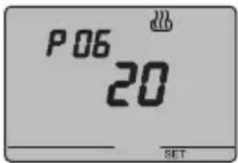
P06 - Setting the cycle time
When the P06 code appears on the screen, set the cycle time using the keys.
The values available are as follows: 5, 10, 20, 30, 40, 50, 60 minutes.
It is possible to set different cycle times for the heating and air-conditioning functions.
Press the key within 30 seconds to confirm the value set.
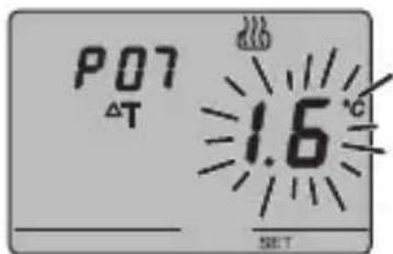
P07 - Setting the proportional regulation differential value
When the P07 appears on the display, set the differential regulation value using the keys.
Possible values from 0.4 °C to 3.2 °C, with a pitch of 0.4 °C.
It is possible to set different regulation differentials for the heating and air-conditioning functions.
Press the key within 30 seconds to confirm the value set.
If a 1 bit value has been selected as the control value when configuring with ETS, move on to NOTE 1, otherwise move on to point P08.
OPERATING INSTRUCTIONS
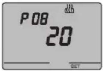
P08 - Minimum percentage value to send the command
When the P08 code appears on the screen, set the percentage resolution to send the command to the thermal regulation control device.
The values available are as follows: 5%, 10%, 20%.
Press the ⓔ key within 30 seconds to confirm the value set.
Move on to NOTE 1.
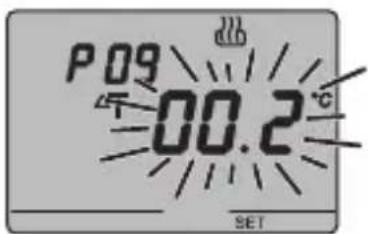
P09 - Setting the regulation differential for 2 point control
When the symbol appears, set the regulation differential time using the keys.
Press the key within 30 seconds to confirm the value set.
The regulation differential is the deviance between the set-point setting and the actual activation temperature. It is possible to set different regulation differentials for the heating and air-conditioning functions. It is recommended to retain the preset values except in special situations.
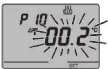
P10 - Speed 1 regulation differential value
When the P10 appears on the display, set the differential regulation value to speed V1.
Possible values: from 0.2 °C to 2 °C with a pitch of 0.1 °C.
Press the ⓚkey within 30 seconds to confirm the value set.
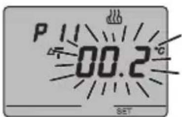
P11 - Speed 2 regulation differential value
When the P11 appears on the display, set the differential regulation value to speed V2.
Possible values: from 0.2 °C to 2 °C with a pitch of 0.1 °C.
Press the key within 30 seconds to confirm the value set. This parameter is significant if the number of fan coil stage set by ETS is greater than 1.
OPERATING INSTRUCTIONS
NOTE 1
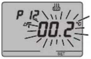
P12 - Speed 3 regulation differential value
When the P12 appears on the display, set the differential regulation value to speed V3.
Possible values: from 0.2 °C to 2 °C with a pitch of 0.1 °C.
Press the key within 30 seconds to confirm the value set. This parameter is significant if the number of fan coil stage set by ETS is greater than 3.
If the device was set as Slave with set point settings on ETS, go to point 14; if set as Slave with mode or Stand alone settings with remote control enabled, go to point P13. In other cases, programming is completed. Press the SET key to return to normal operations.
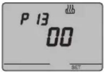
P13 - Enabling/disabling of the Slave function
When the P13 code appears on the display, it is possible to deactivate the Slave function mode and activate the Stand alone function mode and vice-versa (01 = Slave function mode, 00 = Stand alone function mode).
Press the key within 30 seconds to confirm the value set.
If parameter P13=00 (Slave function disabled) go to point P15, if P13=01 (Slave function on), go to point P14.
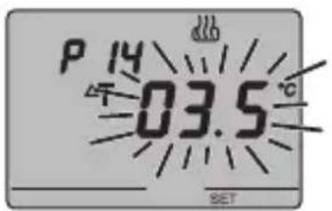
P14 - Set point variation interval for manual override
When P14 appears, select the admissible variation interval (min/max) for the value to be applied to the set point for manual override using the keys. The interval is symmetrical: select 3.5°C to set an interval between -3.5°C and +3.5°C.
Possible values: from 0 °C to 5 °C, with a pitch of 0.1 °C. The programming phase is now complete Press the SET key to return to normal operation mode.
OPERATING INSTRUCTIONS
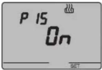
P15 - Enable remote control mode and operation type settings
When P15 appears, enable or disable remote controls using the keys.
(OFF = remote controls OFF, ON = remote controls ON)
The symbol on the display indicates that this option is enabled.
When the remote control option is enabled it is possible to remotely set the operation type and mode, for instance using the EIB GSM remote control unit (GW 90 815).
The programming phase is now complete Press the SET key to return to normal operation mode.
Temporary temperature forcing
In Economy, Precomfort and Comfort operating modes or in Master/Slave with set point control mode, the active temperature set point can be temporarily forced using the keys to set the desired value. Confirm the value by pressing the key or waiting for 5 seconds.
T. , or blin on the screen to indicate that forcing is enabled.
For Slave control mode, set point temperature variation is limited by the P14 - Set point variation interval for manual override parameter value.
Reset and reinstatement of default settings
Press the FAN and SET keys together for 2 seconds, when the device is powered by the bus, to reset the thermostat.
Caution: all the previously set parameters will be cancelled.
When it is turned back on, the thermostat will use the default factory settings. The thermostat will be set to heating in OFF mode.
OPERATING INSTRUCTIONS
Default parameters
| Day of the week | 1: Monday | |
| Time | 00:01 | |
| Heating temperature set-point | T1 | 16 °C |
| T2 | 18 °C | |
| T3 | 20 °C | |
| TFROSTPROTECT | 5 °C | |
| Air-conditioning temperature set-point | T1 | 24 °C |
| T2 | 26 °C | |
| T3 | 28 °C | |
| THIGH TEMPERATURE PROTECTION | 35 °C | |
| Temperature unit of measurement | °C | |
| Control logic | 2 points | |
| Differential regulation for 2 point control | Heating | 0.2 °C |
| Air conditioning | 0.5 °C | |
| Differential regulation for proportional control | 1.6 °C | |
| Cycle time | 20 minutes | |
| Control mode | Slave | |
OPERATING INSTRUCTIONS
Behaviour on the failure and reinstatement of the bus power supply
When the bus power supply fails, the device performs no actions. The time and date are maintained by the buffer power system (rechargeable battery) whilst all the other settings are saved to a non-volatile memory. When the power is supplied by battery only, the device has an autonomy of 36 hours in the following conditions:
- time display active;
• measure and temperature display not active (dashes are displayed); - backlighting inactive;
- front keys are not enabled (except for the simultaneous pressing of FAN and SET).
When there is no bus power the simultaneous pressing of FAN and SET for 2 seconds will cause the rechargeable battery to disconnect inside the device. This function is used to conserve the efficiency of the battery when the device is not used for a long period.
The battery is then automatically reconnected when the device receives power from the bus. The set programs are not lost when there is a failure in the bus connection or when the battery is disconnected.
The device is in full operating mode within a maximum of 5 seconds from reinstatement of the bus power supply.
If the buffer power (rechargeable battery) is absent or disconnected, the thermostat will restart in OFF mode when the bus power is reinstated.
OPERATING INSTRUCTIONS
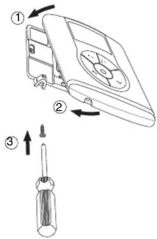
Replacing the Battery
Remove the fastener screws which are under the device, and remove the thermostat from the support base, as seen in the figure below.
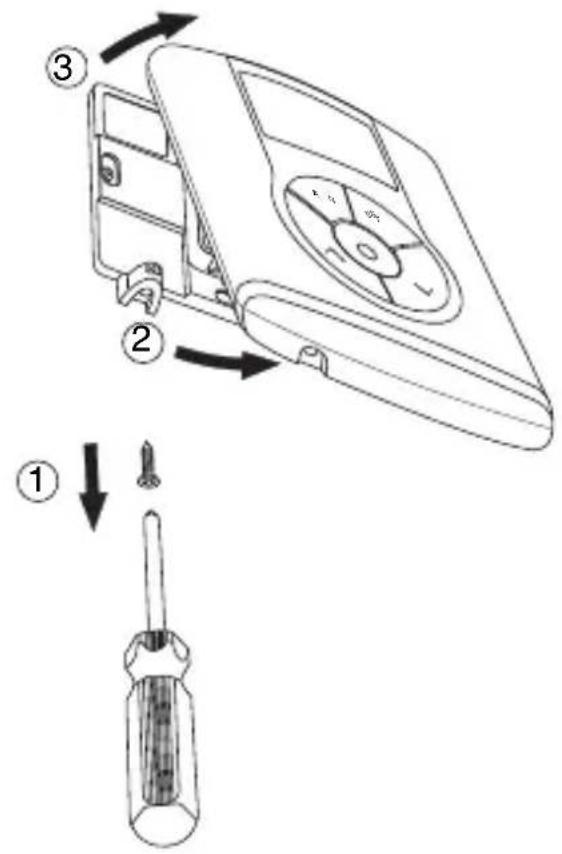
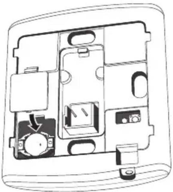
Remove the battery holder cover and replace the rechargeable battery with one of the same type (ML1220), paying attention to the direction of the poles.
natural_image
Cross-sectional diagram of a device casing showing internal components and a directional arrow (no text or symbols)OPERATING INSTRUCTIONS
Replace the thermostat in the support base, as seen in the figure below, and replace the screws under the device.

WARNING
- If the thermostat was not powered by the bus whilst replacing the battery, update the time and date.
- Never throw the battery into a fire.
- The battery is a special waste product and therefore it must be disposed of according to the laws in force and taken to a special collection centre.
Cleaning the thermostat
Use a dry cloth to clean the thermostat.
INSTALLATION INSTRUCTIONS

WARNING: the installation of the device must be exclusively done by qualified personnel, following the regulations in force and the guidelines for KNX/EIB installations.
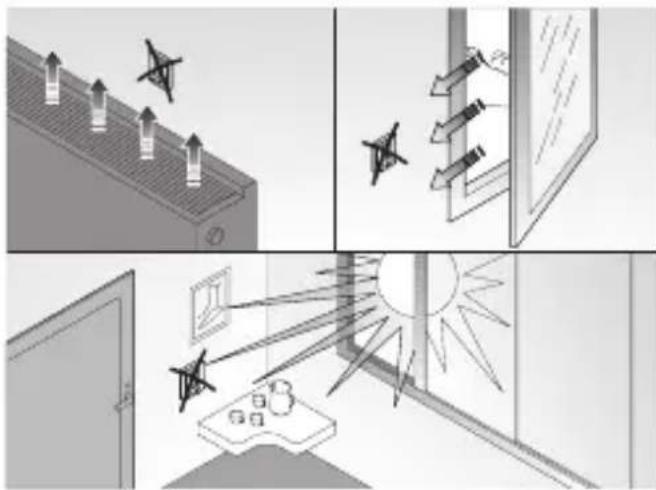
Correct installation position
In order for the thermostat to take correct readings of the ambient temperature, it must not be installed in an alcove, near a door or window, next to radiators or air conditioner units and must not be placed in direct sunlight or in draughty areas.
natural_image
Illustration of four different scenes: ceiling-mounted air pollutants, window with arrows, sunlit windows, and a desk with items (no text or symbols)Assembly of the support base
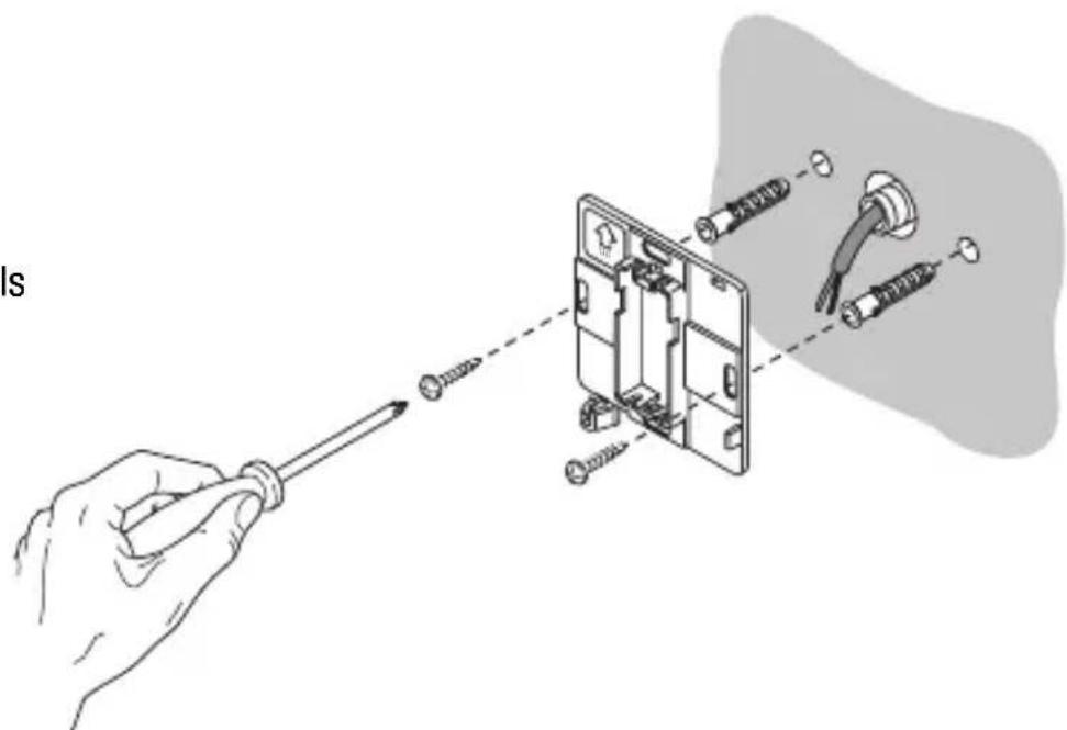
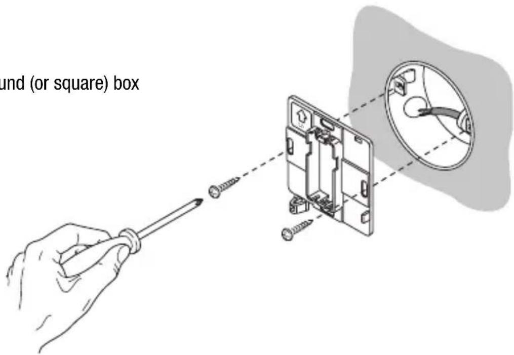
The support base should be positioned at 160 cm from the ground and can be mounted on the wall, using dowels, or on top of a 2-place round or square box (60 mm hole distance).
Mounting with dowels
natural_image
Illustration of a hand using a screwdriver to adjust or install an electrical socket with attached wires (no text or symbols present)INSTALLATION INSTRUCTIONS
Mounting on a round (or square) box
Warnings for KNX/EIB installations
- The length of the bus line between the EIB thermostat and the power supply unit must not exceed 350 metres.
- The length of the bus line between the EIB thermostat and the most distant KNX/EIB device must not exceed 700 metres.
- If possible do not create ring circuits so as to prevent undesirable signals and overloads.
- Keep a distance of at least 4 mm between the individually insulated cables of the bus line and those of the electric line.

- Do not damage the electrical continuity conductor of the shielding.

INSTALLATION INSTRUCTIONS
WARNING: the unused bus signal cables and the electrical continuity conductor must never touch elements under power or the earth conductor.

Electrical connections
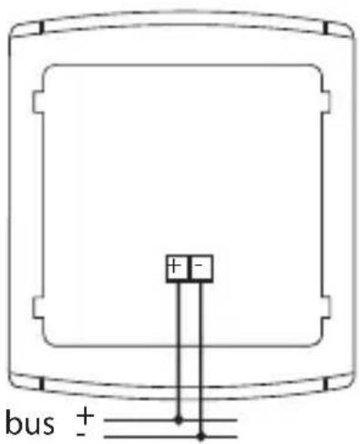
Electrical connections diagram
- Before connecting the KNX/EIB bus, insert the rechargeable buffer memory battery (see Replacing the Battery paragraph).
- Connect the bus cable's red wire to the terminal's red connector (+) and the black wire to the black connector (-). Up to 4 bus lines (wires of the same colour in the same connector) can be connected to the bus terminal.
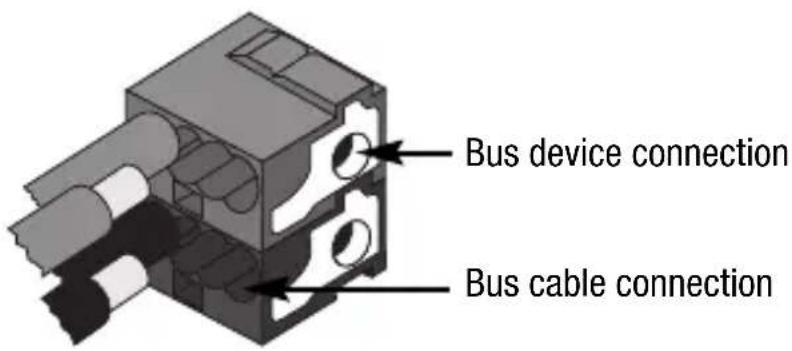
- Insulate the screen, the electrical continuity conductor and the remaining white and yellow wires of the bus cable (should a bus cable with 4 conductors be used), which are not needed.
INSTALLATION INSTRUCTIONS
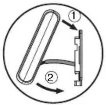
- Insert the bus connector into the special feet of the device. The fastener guides determine the direction it should be inserted.
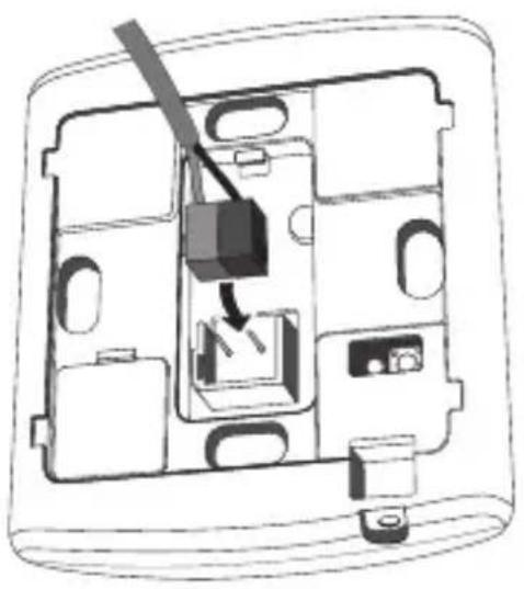
natural_image
Diagram of a device interior showing internal components and a switch mechanism (no text or labels)INSTALLATION INSTRUCTIONS
Completing installation
Position the thermostat on the support base, as seen in the figure below, and fix it in place using the supplied screws.
TECHNICAL DATA
| Communication | KNX/EIB Bus |
| Power supply | By KNX/EIB Bus, 29 V dc SELV+ 1 rechargeable battery type ML1220 3 V to update date/time in the event bus power is out |
| Bus current consumption | 5 mA |
| Bus wire | KNX/EIB TP1 |
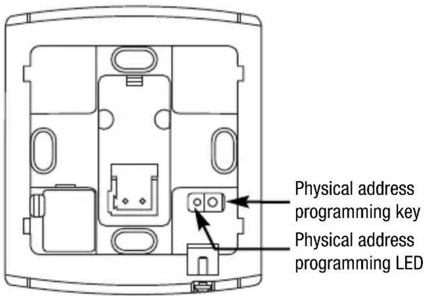
| Control elements | 5 front buttons1 mini physical address programming key |
| Display elements | 1 LED backlit LCD display (timed to user intervention)1 red physical address programming LED |
| Display range temperature | 0 ÷ +45 °C |
| Reading elements | 1 NTC sensorreading resolution: 0.1 °Creading accuracy: ± 0.5 °C to 20 °Cintervals between the next readings: 1 minute |
| Temperature regulation ranges | T frostprotect: +2 ÷ +7 °CT high temperature protection: +30 ÷ +40 °COther set points: +5 ÷ +40 °C |
| Ambit of use | Indoors, dry places |
| Operating temperature | -5 ÷ +45 °C |
| Storage temperature | -25 ÷ +70 °C |
| Relative humidity | Max 93% (no condensation) |
| Bus connection | Slot in terminal, 2 pin ∅ 1 mm |
| Protection rating | IP20 |
| Dimension (L x H x W) | 85 x 95 x 23 mm |
| Reference standards | Low Voltage Directive 2006/95/ECElectromagnetic Compatibility Standard89/336/CEEEN50090-2-2, EN60730-1 |
| Certification | KNX/EIB |
SOMMAIRE
page
AVERTISSEMENTS GÉNÉRAUX
Contenu de la confection 68
DESCRIPTION GENERALE
En bref 69
natural_image
Technical line drawing of a device rear panel with internal compartments and connectors (no text or symbols)natural_image
Simple line drawing of a rectangular object with a starburst and 'SET' label at the bottom (no text or symbols on the object itself)Programmation minutes
natural_image
Simple diagram with a sunburst symbol and text 'SET' at the bottom, no readable text or labels present.
natural_image
Simple diagram with a flame icon and a starburst symbol, no text or labels present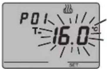

P03chauff - Programmation du Set-point (chauffage)
P03climat - Programmation du Set-point (climatisation)
CONTRÔLE DU FAN COIL
REMARQUE 1

P13 - Activation/désactivation de la fonction Slave
natural_image
Cross-sectional diagram of a device casing showing internal compartments and components (no text or labels)INSTRUCTIONS D'UTILISATION

ATTENTION
natural_image
Four-panel illustration showing ceiling-mounted lighting, window, and sun rays interacting with a door (no text or symbols)natural_image
Diagram of a device interior showing internal components and a switch mechanism (no text or labels)INSTRUCTIONS POUR L'INSTALLATION
Achèvement
DONNÉES TECHNIQUES
natural_image
Simple line drawing of a rectangular object with a starburst symbol and the label 'SET' at the bottom (no readable text or symbols on the object itself)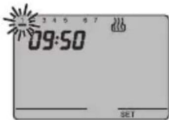

natural_image
Simple diagram with a rectangular shape, a small icon, and a sunburst symbol, labeled 'SET' at the bottom (no text or symbols within the shape)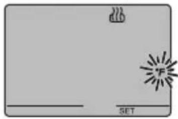
natural_image
Simple diagram with a flame icon and a starburst symbol, no text or labels present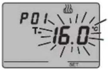
NOTA 1
natural_image
Cross-sectional diagram of a device casing showing internal components and housing (no text or labels)INSTRUCCIONES DE USO

ATENCIÓN
natural_image
Four-panel illustration showing ceiling-mounted air ducts, window with arrows, and sun rays projecting a window (no text or symbols)natural_image
Illustration of a hand using a screwdriver to adjust or install an electrical socket with attached wires (no text or symbols present)natural_image
Diagram of a device interior showing internal components and a switch mechanism (no text or labels)DATOS TÉCNICOS
natural_image
Technical line drawing of a device rear panel with internal compartments and connectors (no text or symbols)Programmiertaste
natural_image
Simple line drawing of a rectangular object with a starburst and 'SET' label at the bottom (no text or symbols on the object itself)natural_image
Simple diagram with a rectangular shape, a small icon, and a starburst symbol, labeled 'SET' at the bottom (no text or symbols within the shape)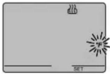
natural_image
Simple diagram with a flame icon and a 'SET' label, no readable text or symbols beyond the label.

P05 - Regellogik
HINWEIS 1
natural_image
Cross-sectional diagram of a device casing showing internal compartments and components (no text or labels)BEDIENUNGSANWEISUNG

ACHTUNG
natural_image
Four-panel illustration showing ceiling-mounted air pollutants, sunlight rays from a window, and a close-up of a window with a sun (no text or symbols)Montage des Bediensockels
natural_image
Illustration of a hand using a screwdriver to adjust or install an electrical component, with no visible text or symbols.natural_image
Diagram of a device interior showing internal components and a switch mechanism (no text or labels)TECHNISCHE DATEN


- AVVERTENZE GENERALI
- ISTRUZIONI D'IMPIEGO
- ATTENZIONE
- DATI TECNICI
- USER INSTRUCTIONS
- INSTALLATION INSTRUCTIONS
- GENERAL INFORMATION
- Pack content
- Summary
- Temperature control
- Fan coil control
- GENERAL DESCRIPTION
- Setting the operation mode
- Temperature reading
- Temperature control in zones
- Scenes
- Other functions
- Control elements and rear display
- Position of the commands
- Command description
- CONTROL BUTTONS Symbol Page
- VDU SIGNALS
- Control mode
- Operation mode
- OPERATING INSTRUCTIONS
- Heating
- Air conditioning
- Operation with fan-coil control activated
- Setting parameters
- Selecting heating/air conditioning
- Setting the day of the week
- Setting the hour
- Setting the minutes
- Setting the temperature unit of measurement
- P01heat - Set Point setting (heating)
- P01cond - Set Point Setting (air conditioning)
- P02heat - Set Point setting (heating)
- P02cond - Set Point setting (air conditioning)
- P03heat - Set Point setting (heating)
- P03cond - Set Point (air conditioning) setting
- P04heat - Set frostprotect temperature value
- P04cond - Set high temperature protection value
- WARNING!
- P05 - Control logic
- POINT CONTROL
- PROPORTIONAL CONTROL
- P06 - Setting the cycle time
- P07 - Setting the proportional regulation differential value
- P08 - Minimum percentage value to send the command
- P09 - Setting the regulation differential for 2 point control
- P10 - Speed 1 regulation differential value
- P11 - Speed 2 regulation differential value
- P12 - Speed 3 regulation differential value
- P13 - Enabling/disabling of the Slave function
- P14 - Set point variation interval for manual override
- P15 - Enable remote control mode and operation type settings
- Temporary temperature forcing
- Reset and reinstatement of default settings
- Caution: all the previously set parameters will be cancelled.
- Behaviour on the failure and reinstatement of the bus power supply
- Replacing the Battery
- WARNING
- Cleaning the thermostat
- Correct installation position
- Assembly of the support base
- Warnings for KNX/EIB installations
- Electrical connections
- Completing installation
- TECHNICAL DATA
- SOMMAIRE
- AVERTISSEMENTS GÉNÉRAUX
- DESCRIPTION GENERALE
- Programmation minutes
- P03chauff - Programmation du Set-point (chauffage)
- P03climat - Programmation du Set-point (climatisation)
- CONTRÔLE DU FAN COIL
- REMARQUE 1
- P13 - Activation/désactivation de la fonction Slave
- INSTRUCTIONS D'UTILISATION
- ATTENTION
- INSTRUCTIONS POUR L'INSTALLATION
- Achèvement
- DONNÉES TECHNIQUES
- INSTRUCCIONES DE USO
- ATENCIÓN
- DATOS TÉCNICOS
- P05 - Regellogik
- HINWEIS 1
- BEDIENUNGSANWEISUNG
- ACHTUNG
- Montage des Bediensockels
- TECHNISCHE DATEN
Brand : Gewiss
Model : GW14793
Category : Thermostat