
GW14791 - Thermostat Gewiss - Free user manual and instructions
Find the device manual for free GW14791 Gewiss in PDF.
| Product type | Wall KNX/EIB chronothermostat |
| Brand | Gewiss |
| Model | GW14791 |
| Power supply | KNX/EIB bus line (5 mA) + 2 AAA alkaline 1.5 V batteries (backup) |
| Display | Timed backlit LCD, 10 control buttons |
| Temperature sensor | Built-in NTC, resolution 0.1 °C, accuracy ±0.5 °C at 20 °C |
| Heating control range | Set points: ANTIFREEZE 2-7 °C, others 5-40 °C |
| Air conditioning control range | Set points: HIGH TEMPERATURE PROTECTION 30-40 °C, others 5-40 °C |
| Operating modes | Automatic, Economy, Precomfort, Comfort, Off/Antifreeze |
| Programming | Weekly, 15-minute resolution, customizable profiles |
| Special functions | Party (1-23 h), Holiday (1-99 d), copy holiday day, temporary override |
| Control logic | 2-point (on/off) or proportional (PWM or continuous 0-100%) |
| Bus connection | 2-pole plug terminal, red wire (+) and black wire (-), up to 4 lines |
| Installation | Wall mounting, height ≈ 160 cm, on plugs or flush box 3 modules |
| Operating temperature | -5 to +45 °C |
| Storage temperature | -25 to +70 °C |
| Relative humidity | Max. 93% (non-condensing) |
| Protection index | IP20 |
| Standards | Low Voltage Directive 2006/95/EC, EMC 89/336/EEC, IEC 64-8 |
| Maintenance and cleaning | Dry cloth only |
| Spare parts | AAA batteries (type), fixing screws, support base, bus terminals |
| Repairability | Battery replacement possible by user; other interventions by qualified personnel |
Frequently Asked Questions - GW14791 Gewiss
User questions about GW14791 Gewiss
0 question about this device. Answer the ones you know or ask your own.
Ask a new question about this device
Download the instructions for your Thermostat in PDF format for free! Find your manual GW14791 - Gewiss and take your electronic device back in hand. On this page are published all the documents necessary for the use of your device. GW14791 by Gewiss.
USER MANUAL GW14791 Gewiss
Summary 39
Position of the rear control buttons 41
Position of the controls 42
Control description 43
Operation mode 44
USER INSTRUCTIONS
Selecting heating/air conditioning 46
Setting parameters 46
Customising the daily programme 55
Temporary temperature forcing 56
Party Function 57
Holiday Function 58
Copying the holiday programme function 59
Low Battery indicator. 60
Reset and reinstatement of default settings 60
Preset programs 61
Preset parameters 62
Behaviour on the failure and reinstatement of the bus power supply 62
Replacing the batteries 63
Cleaning the timer-thermostat 64
INSTALLATION INSTRUCTIONS
Correct installation position. 65
Assembly of the support base 65
Warnings for KMX/EIB installations 66
Electrical connections 67
Completing installation 68
TECHNICAL DATA 69
GENERAL INFORMATION
Warning! The safety of this appliance is only guaranteed if all the instructions given here are followed scrupulously. These should be read thoroughly and kept in a safe place. The Chorus products must be installed in compliance with the requisites of standard CEI 64-8 for devices for domestic use and similar, in non-dusty atmospheres and where special protection against water penetration is not required.
The GEWISS sales organisation is at your disposal for clarifications and technical information.
Gewiss SpA reserves the right to make changes to the product described in this manual at any time and without giving any notice.
Pack content
The wall EIB Timer-Thermostat allows you to automatically manage the temperature in the area it is installed in on a weekly basis. The temperature is regulated by the KNX/EIB actuators which are managed by the Building Automation KNX/EIB bus and control the heating or air-conditioning systems.
When combined with wall EIB thermostats (GW10 793 - GW14 793), it can be used with master functions to regulate the temperature in zones.
The temperature profiles are defined on a weekly basis. It is possible to programme an independent time profile for each day of the week, with a 15 minute resolution and without limits to the daily variations. The timer-thermostat comprises:
- 2 function types: heating and air conditioning;
- 5 operation modes: OFF, Economy, Precomfort, Comfort and Automatic;
- 4 temperature settings for the heating function (T ECONOMY, TPRECOMFORT, TCOMFORT, TFROSTPROTECT.)
- 4 temperature settings for the air conditioning function (TECONOMY, TPRECOMFORT, TCOMFORT, THIGH TEMPERATURE PROTECTION).
The timer-thermostat is powered by the bus line and is fitted with a timed backlit LCD display, 10 control buttons, an integrated sensor to detect the ambient temperature (the value of which is sent to the bus), alkaline batteries (AAA) to maintain the date and time on the display should the power be disconnected from the bus.
GENERAL DESCRIPTION
The device is configured by the ETS software to achieve one of the functions listed below.
Temperature control
- with 2 points, ON/OFF commands or constant regulation (0% 100%)
- proportional control, with PMW commands or constant regulation (0%÷100%)
Setting the operation mode
- from the bus with separate 1 bit objects (OFF, ECONOMY, PRECOMFORT, COMFORT, AUTO)
from the bus with 1 byte objects
Temperature reading
with integrated sensor or temperature probe
- mixed with definition of the relative weight
Temperature control in zones
- with transmission of the operation mode to the slave thermostats
with transmission of the set point to the slave thermostats
Scenes
- memorising and activating the 8 scenes (value 0.63)
Other functions:
- setting of the (OFF, ECONOMY, PRECOMFORT, COMFORT) set point by the bus
- setting the function type (heating/air conditioning) by the bus;
- setting of the time and day by the bus
- transmission of the time and day from the bus to the slave thermostat
- transmission to the bus of the status information (mode, type) and the temperature reading
- management of status information sent from the controlled actuator
The device is installed on the wall using the supplied flange that can be fixed to the wall using dowels or screwed onto a 3 module flush-mounted box.
GENERAL DESCRIPTION
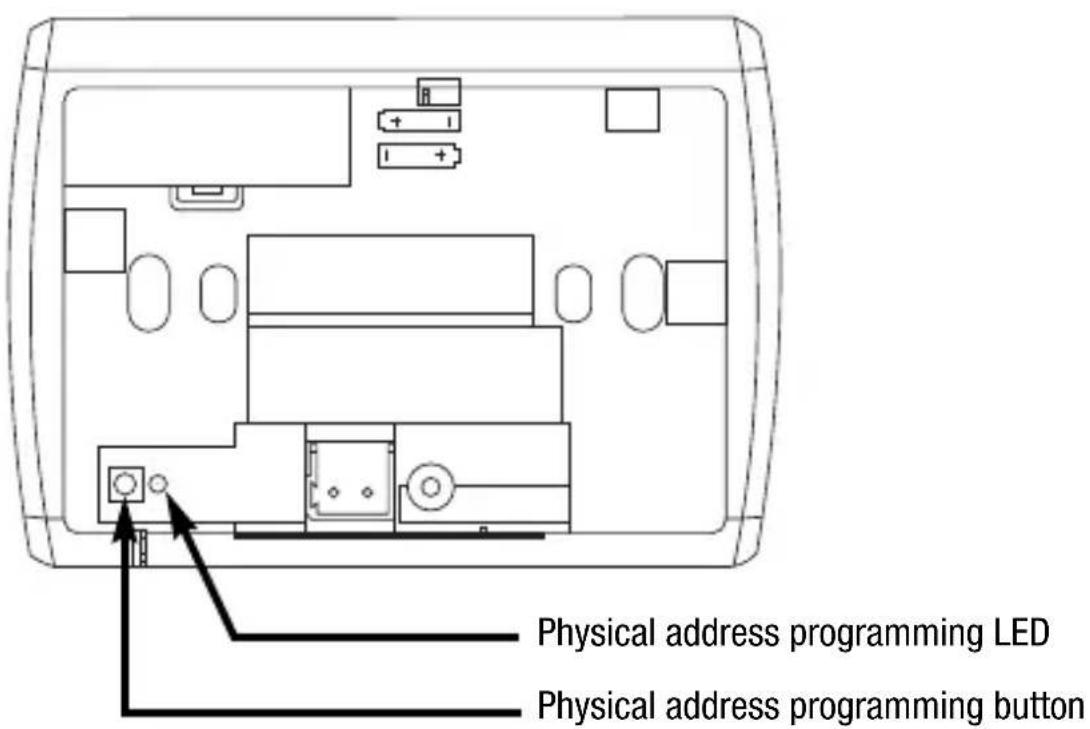
Position of the rear controls
GENERAL DESCRIPTION
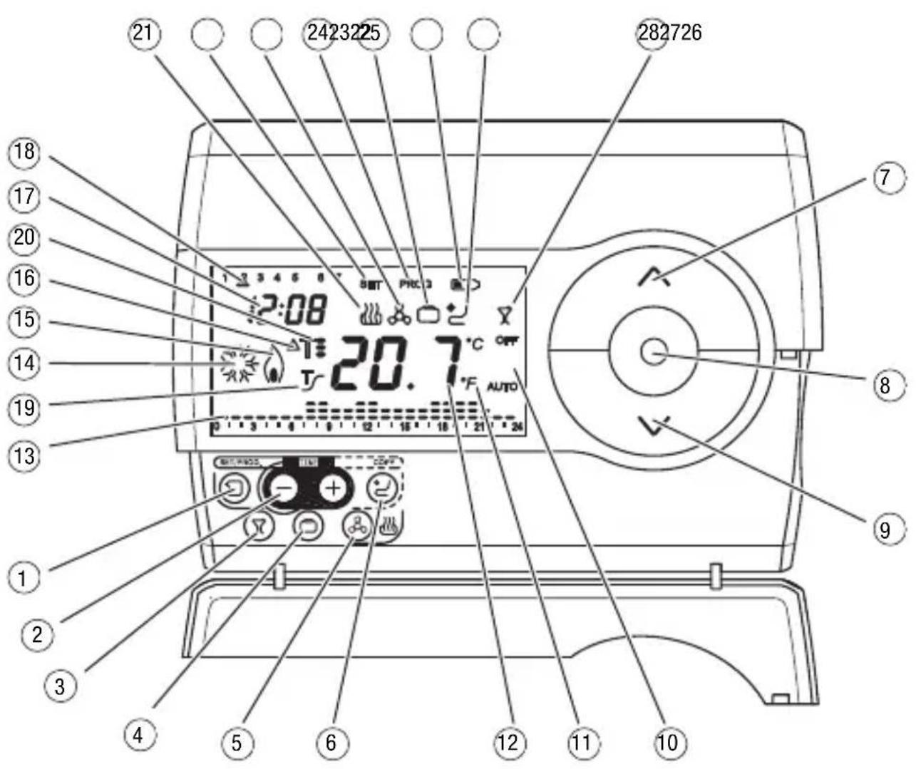
Position of the control buttons
The timer-thermostat is fitted with a display, 3 control buttons which are always accessible and 7 control buttons which can be accessed when the cover is open.
GENERAL DESCRIPTION
Control description
CONTROL BUTTONS Symbol Page
1 Programming / setting
2 Regulating the time
3 Party 57
④ Holiday 58
5 Selecting heating/air conditioning 46
6 Copy 60
(7) Temperature regulation (+)/select settings
8 Select operation mode / confirmation
9 Temperature regulation (-) / select settings
⑥
品
A
SCREEN SIGNALS
10 Operation mode 44
11 Temperature unit of measurement 48
12 Ambient temperature measured
13 Daily program profile 55
14 Activation of air-conditioning 45
15 Activation of heating 45
Thermal differential 53
17Clock 48
Day of the week 48
19 Activation of self-learning function
20 Temperature set-point - operation mode
Heating function
22 Parameter setting status
23 Air conditioning function
24 Programming status
25 Holiday Function
26 Low Batteries
27 Copy holiday programme function
28 Party Function
AUTO
^ C / ^


T
T. T: T
SET

PROG


53
49
45
46
46
53
58
60
59
57
GENERAL DESCRIPTION
Operation Mode
The timer-thermostat has 5 different operation modes:
AUTOMATIC
ECONOMY
PRECOMFORT
COMFORT
- OFF-FROSTPROTECT./HIGH TEMPERATURE PROTECTION
Use the key to switch from one mode to another.
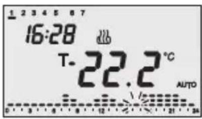
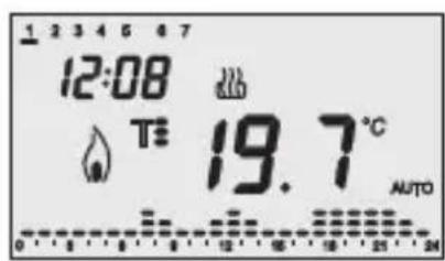
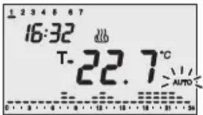
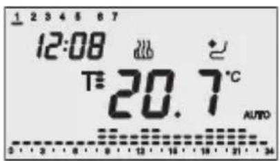
When in automatic mode the timer-thermostat uses a programme that can be customised for each day of the week.
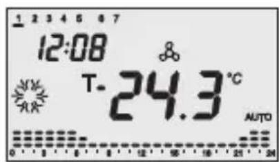
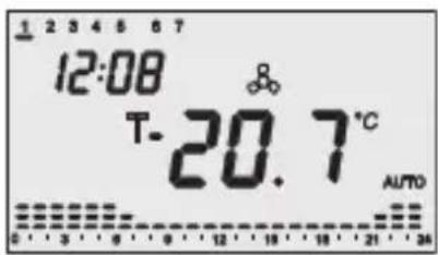
The message "AUTO", the measured ambient temperature and the set point symbol relative to the current quarter-hour are displayed on the screen.
The column relative to the current time with the representation of the active set point blinks in the time profile.
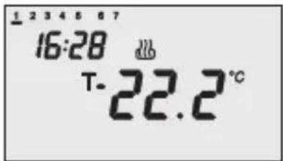
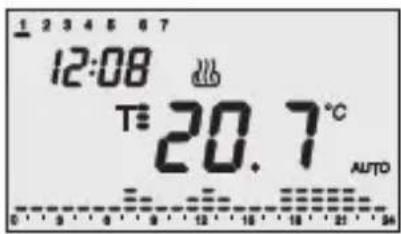
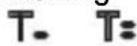
In the economy, precomfort and comfort function modes the timer-thermostat permanently uses the corresponding temperature set-points. The current ambient temperature and the symbol, orT. T: T appear on the screen.
MEANING OF T. T: T:
| Symbol | Heating Air conditioning | |||
| Set point | Operation mode | Set point | Operation mode | |
| Tc | TECONOMY | Economy | TCOMFORT | Comfort |
| Tt | TPRECOMFORT | Precomfort | TPRECOMFORT | Precomfort |
| Tf | TCOMFORT | Comfort | TECONOMY | Economy |
GENERAL DESCRIPTION
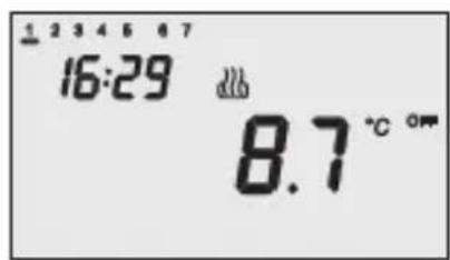
The frostprotect. function is only enabled in heating function mode, when the thermal regulation system is OFF. In this case the timer-thermostat uses the set frostprotect. temperature set-point, re-starting the heating system only when the ambient temperature decreases below TFOSTPROTECT. The message OFF and the measured ambient temperature are displayed on the screen.
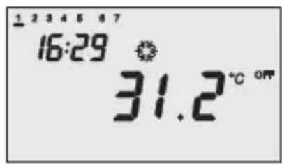
The high-temperature protection function is only enabled in air-conditioning mode, when the thermal regulation system is OFF.
In this case the timer-thermostat uses the set high-temperature set-point, re-starting the air-conditioning system only when the ambient temperature exceeds the HIGH TEMPERATURE PROTECTION.
The message OFF and the measured ambient temperature are displayed on the screen.
The activation of the heating or air-conditioning functions are indicated as followed:
Heating
The symbol indicates that the activation command has been sent to the actuator which controls the boiler. If the load notice has been sent via the ETS and the timer-thermostat does not receive confirmation from the actuator that the same has been activated, the symbol starts to flash. Subsequently, the timer-thermostat sends the activation command again, at one minute intervals, until it receives a positive response.
Air conditioning
The symbol indicates that the activation command has been sent to the actuator which controls the air-conditioner. If the load notice has been sent via the ETS and the timer-thermostat does not receive confirmation from the actuator that the same has been activated, the symbol starts to flash. Subsequently, the timer-thermostat sends the activation command again, at one minute intervals, until it receives a positive response.
Selecting heating/air conditioning
Press the key to switch the function modes from heating to air-conditioning and vice-versa.
Heating
The symbol indicates the heating mode.
Air conditioning
The symbol indicates the air-conditioning mode.
Setting parameters
To set the timer-thermostat parameters:
- use the key to select the function type (heating/air conditioning);
- Press the key once.
The word SET and the clock appears on the screen, and the day of the week cursor starts to flash.
According to the function type, it is now possible to sequentially modify:
USER INSTRUCTIONS
| Day of the week | |
| Hour | |
| Minutes | |
| Temperature unit of measurement | |
| Heating Air conditioning | |
| P01heat - Set Point F01 | cond - Set Point T- |
| P02heat - Set Point F02 | cond - Set Point Tz |
| P03heat - Set Point F03 | cond - Set Point Ts Tz |
| P04heat - Set Point TFROSTPROTECT. | P04cond - Set Point THIGH TEMPERATURE PROTECTION |
| P05heat - Control logic P05cond - Control logic | |
If the control logic = proportional
| P06heat - Cycle time | P06cond - Cycle time |
| P07heat - Proportional regulation differential value | P07cond - Proportional regulation differential value |
| P08 - Minimum percentage value for command sending (visible if the 1 byte command format is selected via ETS) | |
If the control logic = 2 points
| P09heat - 2 point regulation differential value | P09cond - 2 point regulation differential value |
| P10heat - Activation of self-learning function |
| P11 Enabling/Disabling of the master function |
| P12 Day/time sent to the slave devices |
| P13 Period of day/time sent to the slave devices |
| P12 PARTY command sent to the slave devices |
| P12 HOLIDAY command sent to the slave devices |
To scroll the sequence, confirming the values displayed on the screen, press the key until you reach the parameter you want to change.
Press the key again to exit the parameter setting procedure or it will exit automatically after a 30" time-out.
It is necessary to perform both sequences to set the heating and air-conditioning parameters (in the second sequence it is possible to confirm the parameters which are the same, and just change the specific ones).
USERINSTRUCTIONS
Setting the day of the week
When the day of week bar is blinking, select the current day using the keys.
Press the key within 30 seconds to confirm the value set.
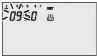
Setting the hour
When the hour figures blink, set the hour using the keys.
Press the key within 30 seconds to confirm the value set.
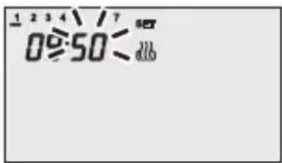
Setting the minutes
When the minutes figures blink, set the minutes using the keys.
Press the key within 30 seconds to confirm the value set.
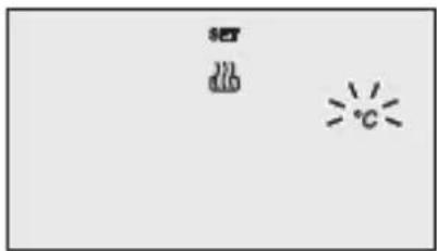
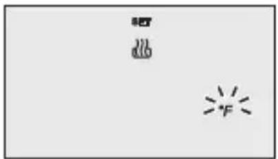
Setting the temperature unit of measurement
When the temperature symbols ^ C or ^ starts to blink, select the temperature unit of measurement using the keys.
Press the key within 30 seconds to confirm the value set.
USERINSTRUCTIONS
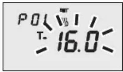
P01heat - Set Point setting (heating)
The temperature value starts to blink when the T- symbol appears. Regulate the Value (TECONOMY) using the keys.
Press the key within 30 seconds to confirm the value set.
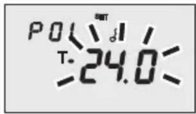
P01cond - Set Point setting (air conditioning)
The temperature value starts to blink when the T. symbol appears. Regulate the Value (T COMFORT) using the keys.
Press the key within 30 seconds to confirm the value set.
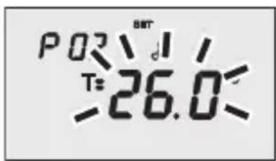
P02heat - Set Point setting (heating)
The temperature value starts to blink when the T's symbol appears. Regulate the value (Tprecomfort) using the Keys.
Press the key within 30 seconds to confirm the value set.
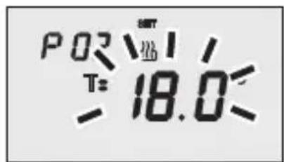
P02cond - Set Point Setting (air conditioning)
The temperature value starts to blink when the T= symbol appears. Regulate the value (T PRECOMFORT) using the keys.
Press the key within 30 seconds to confirm the value set.
USERINSTRUCTIONS

P03heat - Set Point setting (heating)
The temperature value starts to blink when the T symbol appears. Regulate the value (T COMFORT) using the keys.
Press the key within 30 seconds to confirm the value set.
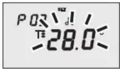
P03cond - Set Point setting (air conditioning)
The temperature value starts to blink when the T symbol appears. Regulate the value (T ECONOMY) using the buttons.
Press the key within 30 seconds to confirm the value set.
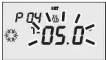
P04heat - Set frostprotect. temperature value
The temperature value starts to blink when the symbol appears. Regulate the frostprotect. temperature value using the buttons.
Press the key within 30 seconds to confirm the value set.
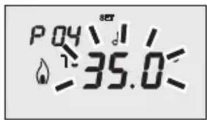
P04cond - Set high temperature protection value
The temperature value starts to blink when the symbol appears. Regulate the high temperature protection value using the buttons.
Press key within 30 seconds to confirm the value set.
WARNING!
The set-point values have the following limits:
- Heating
TFROSTPROTECT


Air conditioning

THIGH TEMPERATURES PROTECTION
USERINSTRUCTIONS
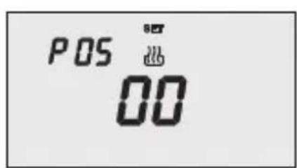
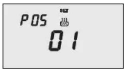
P05 - Control logic
When the P05 code appears on the screen, set the thermal regulation control logic using the keys (00 = 2 point control, 01 = proportional control).
Press the key within 30 seconds to confirm the value set.
It is possible to set different control logics for the heating and air-conditioning functions.
If you select a 2 point control, move on to point P09, for proportional control move on to point P06.
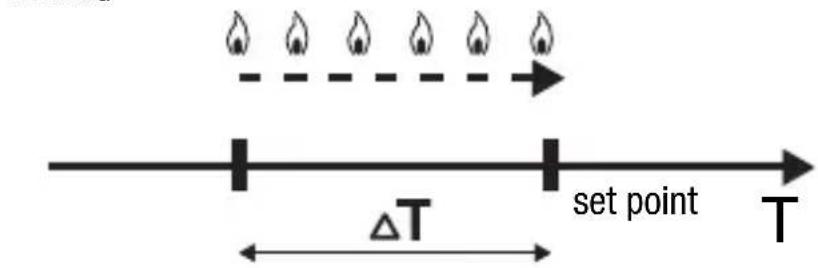
2 POINT CONTROL
The thermal regulation system is switched off when the room temperature is equal to the set point, and is switched back when:
- the temperature is equal to or lower than the set point - T for heating;
- the temperature is equal to or higher than the set point + T for air-conditioning;
The diagrams below show the two function types.
HEATING
AIR CONDITIONING
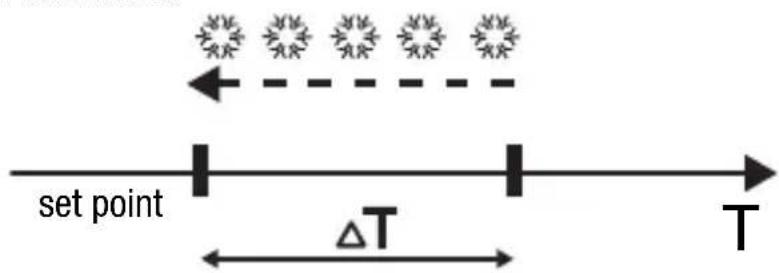
If the command format selected via ETS is 1 bit, the timer-thermostat sends ON/OFF commands; if the command format selected via ETS is 1 byte, the timer-thermostat sends 0% or 100% values.
USER INSTRUCTIONS
PROPORTIONAL CONTROL
At the end of each cycle time, the timer-thermostat checks the ambient temperature and, according to the differences recorded compared to the set point setting, it modulates the activation or deactivation of the boiler (PMW) or it sends a 1 byte command (continuous control) to control the heating or cooling element, according to the command selected by ETS (1 bit or 1 byte).
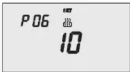
P06 - Setting the cycle time
When the P06 code appears on the screen, set the cycle time using the Keys.
The values available are as follows: 5,10,20,30,40,50,60 minutes. It is possible to set different cycle times for the heating and air-conditioning functions.
Press the key within 30 seconds to confirm the value set.
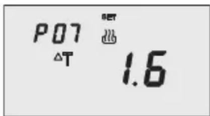
P07 - Setting the proportional regulation differential value
When the P07 code appears on the screen, set the PMW regulation differential value using the keys.
Possible values: from 0.4^ to 3.2^ with a pitch of 0.4^ .
It is possible to set different regulation differentials for the heating and air-conditioning functions. Press the key within 30 seconds to confirm the value set.
If a 1 bit value has been selected as the control value when configuring with ETS, move on to point P11, otherwise move on to point P08.
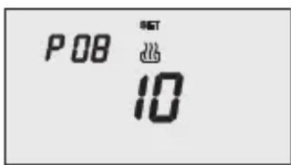
P08 - Minimum percentage value to send the command
When the P08 code appears on the screen, set the percentage resolution to send to the command to the thermal regulation control device. The values available are as follows: 5% , 10% , 20% .
Press the key within 30 seconds to confirm the value set.
USERINSTRUCTIONS
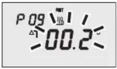
P09 - Setting the 2 point regulation differential value
When the symbol appears, set the differential regulation value using the Keys.
Press the key within 30 seconds to confirm the value set.
The regulation differential is the deviance between the set-point setting and the actual activation temperature. It is possible to set different regulation differentials for the heating and air-conditioning functions. It is recommended to retain the preset values except in special situations.
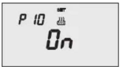
P10 - Enabling self-learning (heating only)
When the symbol appears on the screen, use the keys to enable (ON) or disable (OFF) the function. Press the key within 30 seconds to confirm the value set.
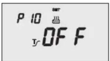
The self-learning function optimises the activation of the heating in advance (max 2 hours).
The timer-thermostat manages the advance automatically, so as to guarantee the set temperature at the beginning of every period of the programmed profile.
This function is activated in heating, in automatic operation mode only.
The following parameters are only significant if the timer-thermostat has been configured via ETS to function as the master device. In all other cases they will be ignored.
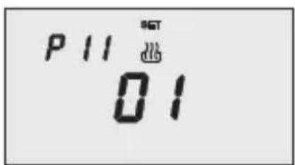
P11 - Enabling/Disabling of the master function
When the P11 code appears on the screen, it is possible to momentarily deactivate the master function mode and activate the stand alone function mode (01 = master function mode, 00 = stand alone function mode).
Press the key within 30 seconds to confirm the value set. If the master function mode has been selected, move on to point P12, otherwise the procedure has now been completed.
USERINSTRUCTIONS
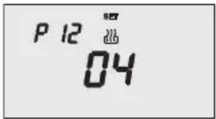
P12 - Sending day/time to the slave devices
When the P12 code appears on the screen, it is possible to define when the timer-thermostat should send the date and time to align these parameters in the slave devices. (00 = the message is never sent, 01 = the message is only sent when the power supply returns, 02 = the message is only sent when the set time changes, 03 = the message is sent when the power supply returns or when the set time changes, 04 = the message is sent when the power supply returns, when the set time changes and at the frequency indicated in P13). Press the key within 30 seconds to confirm the value set.
If the 04 option has been selected, move on to point P13, otherwise move on to point P14.
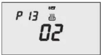
P13 - Day/time sending period
When the P13 code appears on the screen, it is possible to set the sending period for the date and time to align these parameters in the slave devices etc. (00 = every 6 hours, 01 = every 12 hours, 02 = every 24 hours, 03 = every week).
Press the key within 30 seconds to confirm the value set.
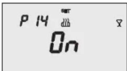
P14 - Sending the PARTY command to the slave devices
When the P14 code appears on the screen, it is possible to use the keys to enable (ON) or disable (OFF) the extension of the PARTY command to the slave devices to the timer-thermostat.
Press the key within 30 seconds to confirm the value set.
USERINSTRUCTIONS
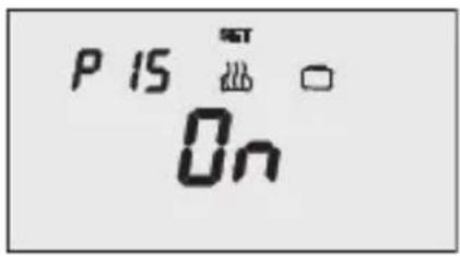
P15 - Sending the HOLIDAY command to the slave devices
When the P15 code appears on the screen, it is possible to use the keys to enable (ON) or disable (OFF) the extension of the HOLIDAY command to the slave devices to the timer-thermostat. Press the key within 30 seconds to confirm the value set.
The parameter setting procedure has now been completed. Press the key to return to normal operating mode.
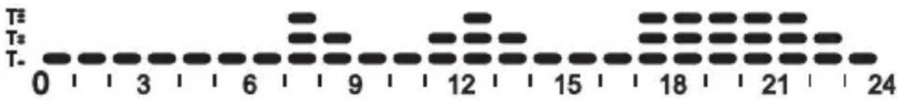
Customising the daily programme
To customise the preset daily programme, or modify the settings, press the key twice.
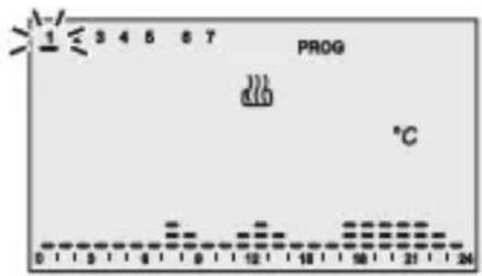
The message "PROG" is displayed on the screen, while the bar of the first day of the week starts to blink. Select the required day using the keys. Press the key within 30 seconds to confirm the selection.
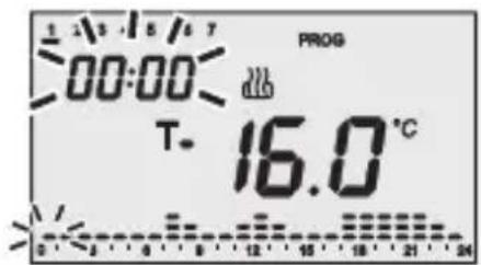
After confirmation of the day, the current profile, relative to the day selected, is displayed on the screen. The time will start to blink.
Follow the steps below to customise the settings:
1 - select the starting time for the change in temperature
2 - set the new temperature set point
3 - completing the customisation process
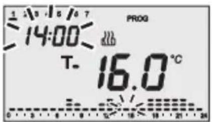
1 - select the starting time for the change in temperature
Use the keys to modify the time until the time for modifying the proposed profile is reached: the column relative to the time selected will blink during the increment of the time profile. The time is decremented/incremented in steps of 15 minutes each time the keys are pressed, so it is possible to define up to 4 programming periods each hour.
USERINSTRUCTIONS
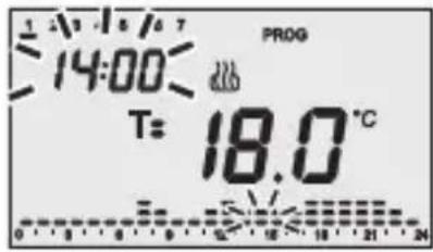
2 - setting the new temperature set point
The current set point value is indicated on the screen by the symbol T_- , T_+ or T_-
The keys are then used to select the new set point, which will be applied to the time profile up to the next variation present in the program.
3 - Completing the customisation process
After repeating steps 1 and 2 to reach the desired temperature hour profile, it is possible to:
- copy the programme to the next day and confirm the performed programming phase by pressing the key within 30 seconds, or
- confirm the performed programming without copying it, by pressing the key within 30 seconds (this moves the programming on to the next day automatically).
Press the key on completion of weekly programming to return to normal operation.
To activate the program, select AUTO operation mode by pressing the key until the message AUTO is displayed on the screen.
Temporary temperature forcing
It is possible to temporarily force the active temperature set point in AUTO, Economy, Precomfort and Comfort operation modes by using the keys to set the required value.
Confirm the new value by pressing the key or waiting for 5 seconds.
The word AUTO will flash on the screen to indicate forcing is enabled or, in the other cases, when T or T flashes. The forcing of the AUTO operation mode remains active until the next variation in the temperature time profile.
USERINSTRUCTIONS
Party Function
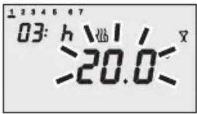
When in AUTO, Economy, Precomfort and Comfort mode the Party function allows you to temporarily exclude the set operation mode and enable the comfort mode with an adjustable set point, for a period of time of from 1 - 23 hours.
This function can be used, for instance, to set a more comfortable temperature during a dinner or a party etc.
Press the key twice to enable the function.
The symbol appears on the screen, whilst the setT point value flashes.
Use the Keys to set the desired temperature.
Use the keys to set the number of hours for which the Party function should be enabled, which is then indicated in the top left hand corner of the screen.
Press the key or wait 5 seconds to confirm the setting made.
When the function is enabled, it is possible to change the set point value pressing the keys and the activation period using the keys.
The count of the hours is decremented during operation.
The Party function remains active until the set period elapses.
When the set time expires, the Party function is automatically disabled and the timer-thermostat returns to its regular operation mode.
Press the key to disable the Party function before the expiry time.
USERINSTRUCTIONS
Holiday Function
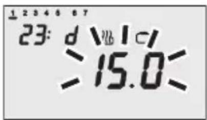
When in AUTO, Economy, Precomfort and Comfort mode the Holiday function allows you to temporarily exclude the set operation mode and enable the Economy mode with an adjustable set point, for a period of time of from 1 – 99 days.
This function can be used, for instance, to set the thermal regulation system so it runs economically during a holiday period, or during a prolonged period of absence, and adjusts the settings the day you return.
Press the key twice to enable the function.
The symbol appears on the screen, whilst the set point value flashes.

Use the Keys to set the desired temperature.
Use the keys to set the number of days for which the Holiday function should be enabled, which is then indicated in the top left hand corner of the screen.
Press the key or wait 5 seconds to confirm the setting made.
When the function is enabled, it is possible to change the set point value pressing the keys and the activation period using the keys.
The count of the days is decremented during operation.
The Holiday function remains on until the set expiry date, which ends at midnight. When calculating the number of day, always include the current day.
For instance, if you want to set the Holiday function on Friday evening so that it ends on Sunday at midnight, you should set 3 days (Friday, Saturday and Sunday).
When the set time expires, the Holiday function is automatically disabled and the timer-thermostat returns to its regular operation mode.
Press the key to disable the Holiday function before the expiry time.
Copying the holiday programme function
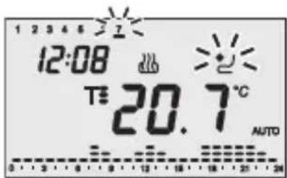
In AUTO mode it is possible to copy the holiday profile (7) to any other day of the week. This function can be activated up to 6 days before the selected day.
This function is particularly useful when, for instance, there is a day's holiday during the week.
Press the key to copy the holiday profile.
The symbol and the holiday day cursor will flash on the display.
Use the keys to select the day of the week to which the holiday profile should be copied.
Press the key or wait 30 seconds to confirm the setting made.
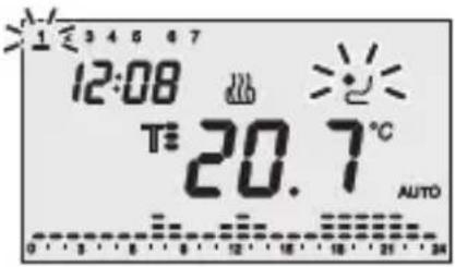
When the function is enabled, press the key to view the day to which the holiday profile was copied; the corresponding cursor will flash on the display.
If you wish to disable the function, press the again; if you wish to change the day of the week, use the + keys and press the key, or wait 30 seconds, to confirm the new settings.
During the day the symbol indicator light is always ON.
The validity of the holiday copy function is temporary; at midnight of the selected day the system returns to the normal weekly profile programme.
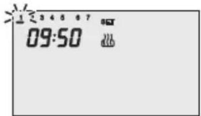
Low Battery indicator
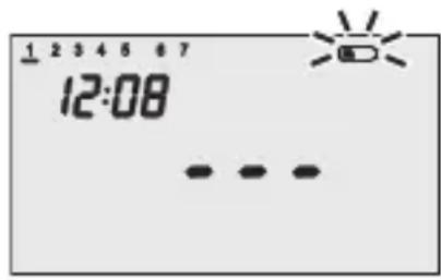
When the batteries are low and there is not bus power the symbol will start to flash on the screen. The temperature indications also disappear from the screen and it is necessary to replace the batteries as soon as possible.
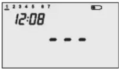
When the symbol is ON with a fixed light, it is essential to replace them immediately.
The batteries are only used to preserve the time and date settings when there is no bus KNX/EiB power (all the other settings are stored in the non-volatile memory).
When the bus power is present it will always function even without batteries.
Reset and reinstatement of default settings
Press the and keys altogether to completely rest the timer-thermostat.
Caution: all the previously set parameters and customised programmes will be cancelled.
When it is turned back on, the timer-thermostat will use the default factory settings. The timer-thermostat will be set to heating, in OFF mode and the Party and Holiday functions will not be enabled.
USERINSTRUCTIONS
Preset programs
The timer-thermostat has 2 preset programs, one for heating and one for air conditioning.
HEATING PROGRAM
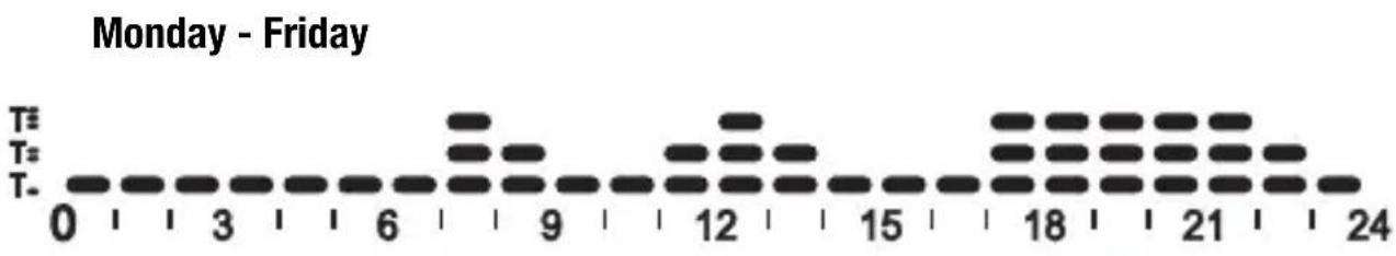
Saturday - Sunday
AIR CONDITIONING PROGRAM

Every day of the week
These preset programs can be modified and personalised according to one's own requirements. To change the preset parameters, follow the instructions provided in the "Customising the daily programme" paragraph.
Preset parameters
| Day of the week | 1: Monday | |
| Hour | 00:00 | |
| Heating temperature set-point | T. | 16 °C |
| T: | 18 °C | |
| T3 | 20 °C | |
| TFROSTPROTECT | 5 °C | |
| Air-conditioning temperature set-point | T. | 24 °C |
| T: | 26 °C | |
| T3 | 28 °C | |
| THIGH TEMPERATURE PROTECTION | 35 °C | |
| Self-learning | OFF | |
| Differential regulation | Heating | 0.2 °C |
| Air conditioning | 0.5 °C | |
| Temperature unit of measurement | °C | |
Behaviour on the failure and reinstatement of the bus power supply
When the bus power supply fails, the device performs no actions. The time and date are maintained by the buffer power system (batteries) whilst all the other settings are saved to a non-volatile memory. The device is in full operating mode within a maximum of 5 seconds from reinstatement of the bus power supply.
If the buffer power (battery) is absent, the timer-thermostat will restart in OFF mode when the bus power is reinstated.
USERINSTRUCTIONS
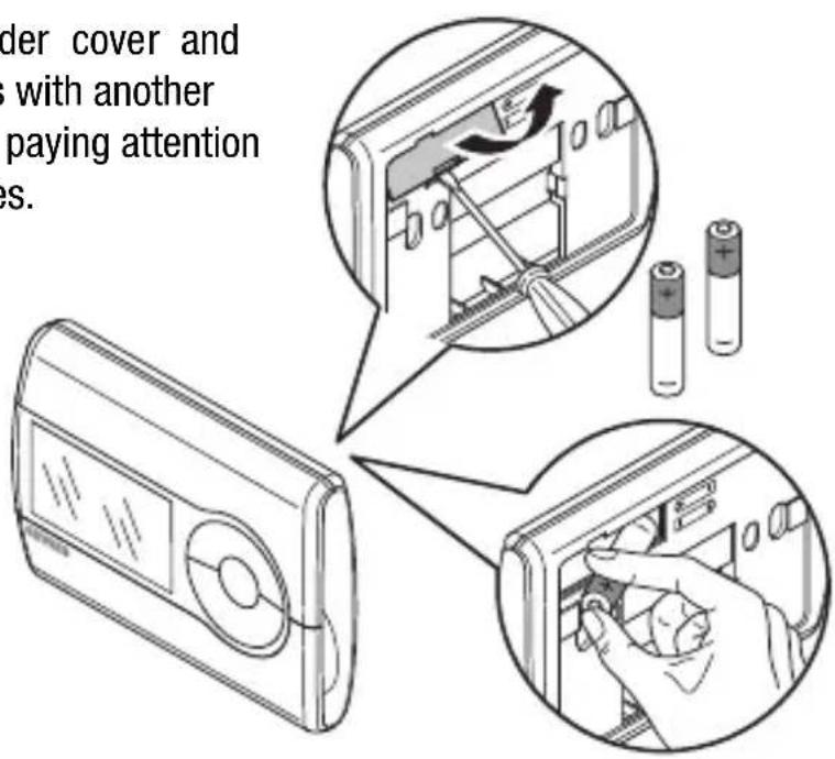
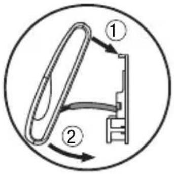
Replacing the batteries
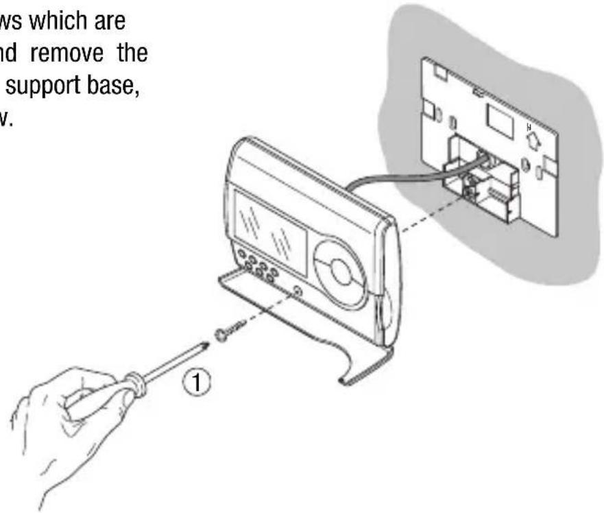
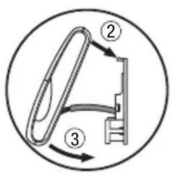
Remove the fastener screws which are under the front cover, and remove the timer-thermostat from the support base, as seen in the figure below.
Remove the battery holder cover and replace the dead batteries with another two 1.5 V (AAA) batteries, paying attention to the direction of the poles.
USERINSTRUCTIONS
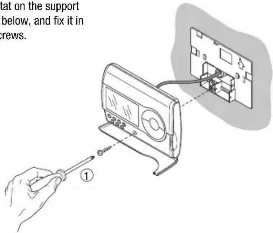
Replace the timer-thermostat on the support base, as seen in the figure below, and fix it in place using the supplied screws.

WARNING:
- If the timer-thermostat was not powered by the bus whilst replacing the battery, update the time and date.
- Replace all the batteries at the same time.
- Never use old and new batteries together.
- Always use the same type of batteries (do not mix alkaline and carbon zinc batteries).
- Never throw the batteries into a fire.

- The batteries are a special waste product and therefore they must be disposed of according to the laws in force and taken to a special collection centre.
Cleaning the timer-thermostat
Use a dry cloth to clean the timer-thermostat.
INSTALLATION INSTRUCTIONS

WARNING: the installation of the device must be exclusively done by qualified personnel, following the regulations in force and the guidelines for KNX/EIB installations.
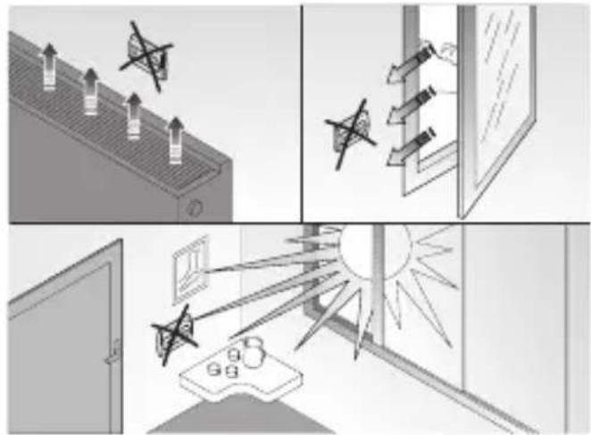
Correct installation position
In order for the timer-thermostat to take correct readings of the ambient temperature, it must not be installed in an alcove, near a door or window, next to radiators or air conditioner units and must not be placed in direct sunlight or in draughty areas.
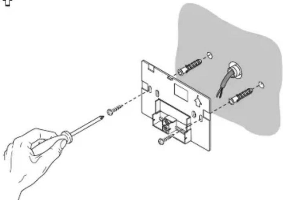
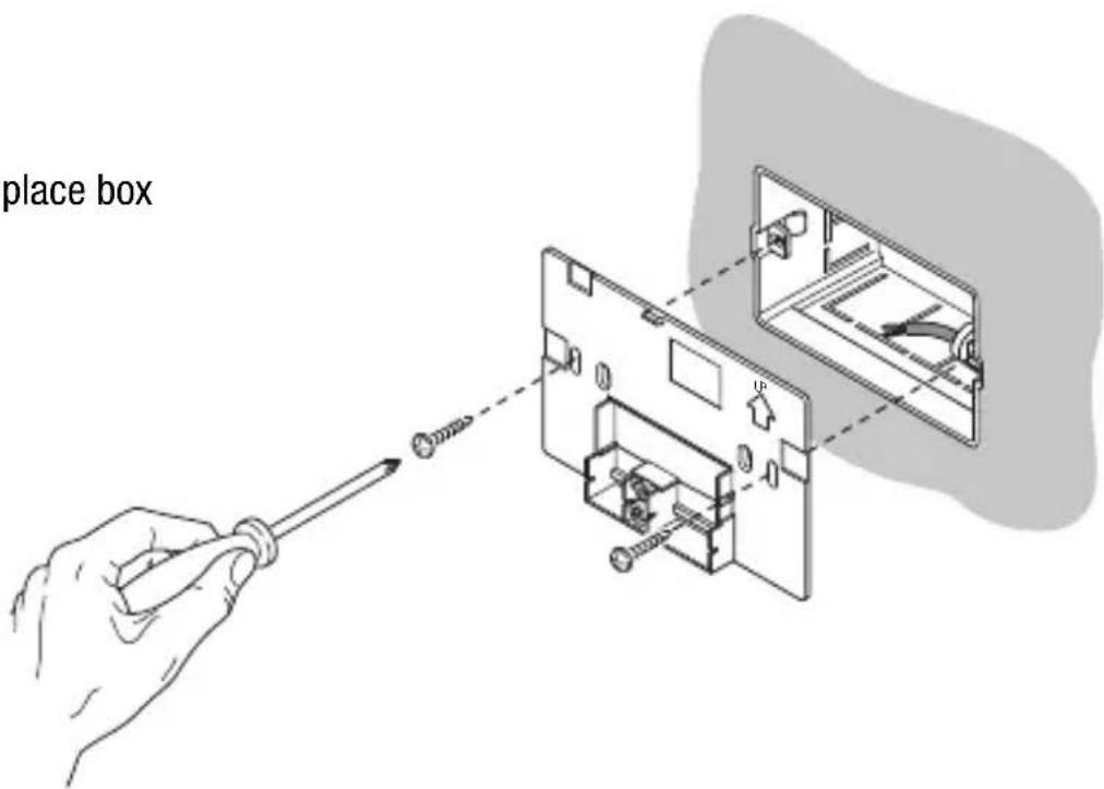
Assembly of the support base
The support base should be positioned at 160~cm from the ground and can be mounted on the wall, using dowels, or on top of a 3-place box.
WARNING : When mounting the support base, make sure you follow the directions indicated by the arrow .
Mounting with dowels
INSTALLATION INSTRUCTIONS
Mounting on a 3-place box
Warnings for KNX/EIB installations
- The length of the bus line between the EIB timer-thermostat and the power supply unit must not exceed 350 metres.
- The length of the bus line between the EIB timer-thermostat and the most distant KNX/EIB device must not exceed 700 metres.
- If possible do not create ring circuits so as to prevent undesirable signals and overloads.
- Keep a distance of at least 4mm between the individually insulated cables of the bus line and those of the electric line.
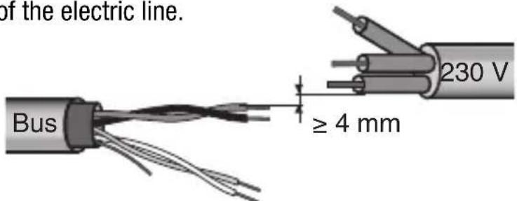
- Do not damage the electrical continuity conductor of the shielding.

INSTALLATION INSTRUCTIONS

WARNING: the unused bus signal cables and the electrical continuity conductor must never touch elements under power or the earth conductor.
Electrical connections
Electrical connections diagram
- Before connecting the KNX/EIB bus, insert the buffer memory batteries (see Replacing the Batteries paragraph).
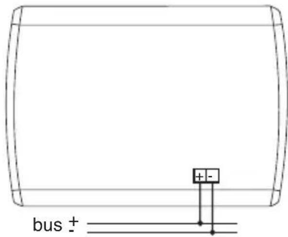
- Connect the bus cable's red wire to the terminal's red connector (+) and the black wire to the black connector (-). Up to 4 bus lines (wires of the same colour in the same connector) can be connected to the bus terminal.
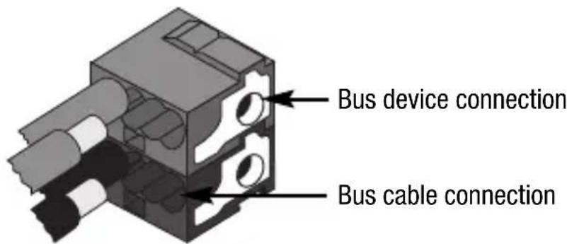
- Insulate the screen, the electrical continuity conductor and the remaining white and yellow wires of the bus cable (should a bus cable with 4 conductors be used), which are not needed.
INSTALLATION INSTRUCTIONS
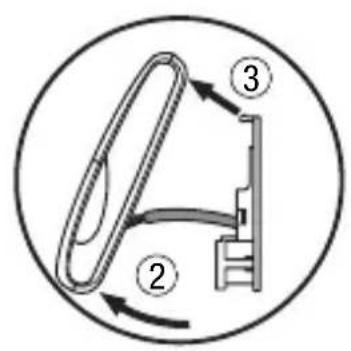
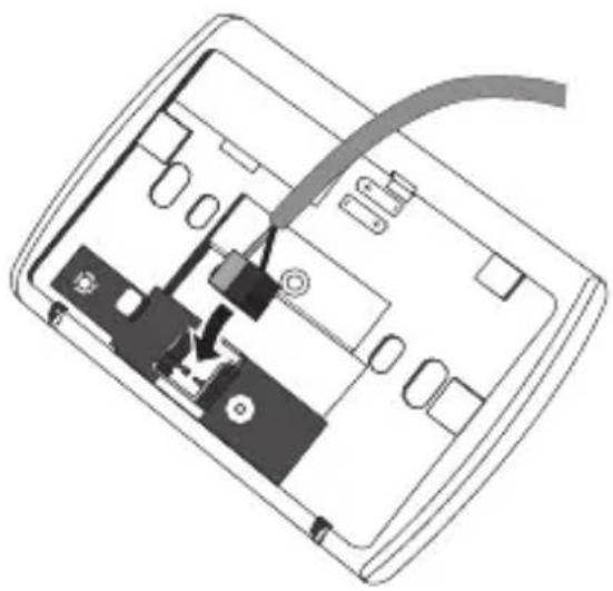
- Insert the bus connector into the special feet of the device. The fastener guides determine the direction it should be inserted.
Completing installation
Position the timer-thermostat on the support base, as seen in the figure below, and fix it in place using the supplied screws.
Communication KNX/EIB Bus
Power Supply By KNX/EIB Bus, 29 V dc SELV
- 2 1.5 V AAA Alkaline batteries to update date
and time when there is a bus power failure
Bus current consumption 5mA
Bus cable KNX/EIB TP1
Control elements 1 mini physical address programming key,
10 command and configuration buttons
Display elements 1 LED backlit LCD display (timed to user
intervention),
1 red physical address programming LED
Temperature display range 0 ÷ +45^ C
Reading elements 1 NTC sensor
read resolution: 0.1^
read accuracy: ± 0.5^ to 20^
intervals between the next readings: 1 minute
Temperature regulation ranges T
FROSTPROTECT.: +2 ÷ +7^ C
THIGH TEMPERATURE PROTECTION +30÷ +40^
Other set points: +5 ÷ +40^ C
Ambit of use Indoors, dry places
Operating temperature -5 ÷ +45^ C
Storage temperature -25 ÷ +70 °C
Relative humidity Max 93% (no condensation)
Bus connection Slot in terminal, 2 pin 1 mm
Protection rating IP20
Size (L x H x W) 130 x 92 x 23 mm
Reference standards Low Voltage Standard 2006/95/CE
Electromagnetic Compatibility Standard 89/336/CEE
Certifications KNX/EIB
SOMMAIRE
page
AVERTISSEMENTS GÉNÉRAUX
Programmation minutes
Communication Bus KNX/EIB
Alimentation Avec bus KNX/EIB, 29 V cc SELV
Cable bus KNX/EIB TP1
Dimension (B x H x P) 130 x 92 x 23 mm
Certifications KNX/EIB
INDICE
Cable bus KNX/EIB TP1
Elementos de mando 1 tecla de miniatura de programacion direccion fisica
According to article 9 paragraph 2 of the European Directive 2004/108/EC, the responsible for placing the apparatus on the Community market is:
Gewiss S.p.A Via A. Volta, 1-24069 Cenate Sotto (BG) Italy Tel: +39 035 946 111 Fax: +39 035 945 270 E-mail: qualitymarks@gewiss.com


- USER INSTRUCTIONS
- INSTALLATION INSTRUCTIONS
- GENERAL INFORMATION
- Pack content
- GENERAL DESCRIPTION
- Temperature control
- Setting the operation mode
- Temperature reading
- Temperature control in zones
- Scenes
- Other functions:
- Position of the rear controls
- Position of the control buttons
- Control description
- CONTROL BUTTONS Symbol Page
- SCREEN SIGNALS
- Operation Mode
- Heating
- Air conditioning
- Selecting heating/air conditioning
- Setting parameters
- USERINSTRUCTIONS
- Setting the day of the week
- Setting the hour
- Setting the minutes
- Setting the temperature unit of measurement
- P01heat - Set Point setting (heating)
- P01cond - Set Point setting (air conditioning)
- P02heat - Set Point setting (heating)
- P02cond - Set Point Setting (air conditioning)
- P03heat - Set Point setting (heating)
- P03cond - Set Point setting (air conditioning)
- P04heat - Set frostprotect. temperature value
- P04cond - Set high temperature protection value
- WARNING!
- P05 - Control logic
- POINT CONTROL
- PROPORTIONAL CONTROL
- P06 - Setting the cycle time
- P07 - Setting the proportional regulation differential value
- P08 - Minimum percentage value to send the command
- P09 - Setting the 2 point regulation differential value
- P10 - Enabling self-learning (heating only)
- P11 - Enabling/Disabling of the master function
- P12 - Sending day/time to the slave devices
- P13 - Day/time sending period
- P14 - Sending the PARTY command to the slave devices
- P15 - Sending the HOLIDAY command to the slave devices
- Customising the daily programme
- - select the starting time for the change in temperature
- - setting the new temperature set point
- - Completing the customisation process
- Temporary temperature forcing
- Party Function
- Holiday Function
- Copying the holiday programme function
- Low Battery indicator
- Reset and reinstatement of default settings
- Caution: all the previously set parameters and customised programmes will be cancelled.
- Preset programs
- HEATING PROGRAM
- AIR CONDITIONING PROGRAM
- Behaviour on the failure and reinstatement of the bus power supply
- Replacing the batteries
- WARNING:
- Cleaning the timer-thermostat
- Correct installation position
- Assembly of the support base
- Warnings for KNX/EIB installations
- Completing installation
- SOMMAIRE
- AVERTISSEMENTS GÉNÉRAUX
- Programmation minutes
- INDICE
Brand : Gewiss
Model : GW14791
Category : Thermostat