
GW14763 - Thermostat Gewiss - Free user manual and instructions
Find the device manual for free GW14763 Gewiss in PDF.

| Product Type | KNX/EIB Wall Thermostat |
| Brand | Gewiss |
| Model | GW14763 |
| Category | Thermostat |
| Power Supply | KNX/EIB bus, 5 mA; rechargeable battery ML1220 3 V for backup |
| Main Functions | Room temperature management, heating and cooling modes, 4 operating modes (Off, Economy, Precomfort, Comfort), 3 control algorithms (2-point, PWM, fan coil), backlit LCD display, 5 control buttons, scheduling, remote control via KNX bus |
| Display Elements | Backlit LCD display (timed) + red programming LED |
| Temperature Sensor | NTC, resolution 0.1 °C, accuracy ±0.5 °C at 20 °C, measurement every 1 min |
| Control Range | Set points: +5 to +40 °C; Frost protection: +2 to +7 °C; High temperature protection: +30 to +40 °C |
| Operating Temperature | -5 to +45 °C |
| Storage Temperature | -25 to +70 °C |
| Relative Humidity | Max 93% non-condensing |
| Protection Rating | IP20 |
| Bus Connection | 2-pin plug-in terminal Ø 1 mm |
| Maintenance and Cleaning | Clean with a dry cloth only |
| Safety | Installation by qualified personnel according to IEC 64-8; compliance with low voltage and electromagnetic compatibility directives |
| Spare Parts and Repairability | Replaceable rechargeable battery type ML1220; reset and factory settings restoration possible |
| General Information | Wall thermostat for KNX/EIB system, compatible with Easy base unit (GW 90 831), allows multi-zone regulation with Easy chronothermostat |
Frequently Asked Questions - GW14763 Gewiss
User questions about GW14763 Gewiss
0 question about this device. Answer the ones you know or ask your own.
Ask a new question about this device
Download the instructions for your Thermostat in PDF format for free! Find your manual GW14763 - Gewiss and take your electronic device back in hand. On this page are published all the documents necessary for the use of your device. GW14763 by Gewiss.
USER MANUAL GW14763 Gewiss
Easy wall thermostat
Thermostat Easy - mural
Termostato Easy - de pared
Dimensione (B x H x P) 85 x 95 x 23 mm
Summary 35
Position of the controls 36
Control description 37
Control mode 38
Operation mode 38
USER INSTRUCTIONS
Setting parameters 40
Reset and reinstatement of default settings 50
Temporary temperature forcing 50
Preset parameters 51
Behaviour on the failure and reinstatement of the bus power supply 52
Replacing the battery 53
Cleaning the thermostat 54
INSTALLATION INSTRUCTIONS
Correct installation position 55
Assembly of the support base 55
Warnings for KNX/EIB installations 56
Electrical connections 57
Initialization with the Easy base unit 58
Completing installation 59
Programming with the Easy base unit 59
TECHNICAL DATA 62
GENERAL INFORMATION
Warning! The safety of this appliance is only guaranteed if all the instructions given here are followed scrupulously. These should be read thoroughly and kept in a safe place. The Chorus products must be installed in compliance with the requisites of standard CEI 64-8 for devices for domestic use and similar, in non-dusty atmospheres and where special protection against water penetration is not required.
The GEWISS sales organisation is at your disposal for clarifications and technical information.
Gewiss SpA reserves the right to make changes to the product described in this manual at any time and without giving any notice.
Pack content
The wall-mounting Easy Thermostat allows you to manage the temperature in the area it is installed in. The temperature is regulated by the KNX/EIB actuators which are managed by the Home Automation KNX/EIB bus and control the heating or air-conditioning elements, including the fan coils. When combined with the wall Easy Timer Thermostat (GW 10 761 - GW 14 761), from which it receives the operation type and mode via the bus, it is possible to create multi-zone thermal regulation systems.
The set-point values used by the thermostat are set locally.
The thermostat has:
- 2 function types: heating and air conditioning;
- 4 operation modes: OFF, Economy, Precomfort and Comfort;
- 4 temperature settings for the heating function (Teconomy, Tprecomfort, Tcomfort, Tfrostprotect)
- 4 temperature settings for the air-conditioning function (Teconomy, Tprecomfort, Tcomfort, Thigh_temperature_protection);
- 3 control algorithm which can be set locally: with 2 points (ON/OFF command), PI (PWM type control) and a fan coil speed control (automatic or manual).
The thermostat is powered by the supplied bus line and is fitted with a timer backlit LCD display, 5 control buttons, an integrated sensor to detect the ambient temperature (the value of which is sent to the bus every 15 minutes), a rechargeable battery (included) to maintain the date and time on the display (when power is disconnected from the bus).
The thermostat output channels can be configured to:
- send the ON/OFF command to the KNX/EIB actuators (max 2) that control the heating / air-conditioning elements;
- regulate the fan-coil speed (max 3 speeds);
- transmit the settings (operation type and mode) and the current data (read temperature) to other devices, for instance the GSM remote control unit.
The thermostat input channels can be configured to:
- remotely control the thermostat operation type and mode with other KNX/EIB devices (for instance the timer-thermostat or the Easy GSM remote control unit);
- manage scenes, associating a function type or mode to a specific scene;
- manage an incoming signal, for instance a contact when a window is opened, to temporarily switch off the thermostat.
The device is installed on the wall using the supplied flange that can be fixed to the wall using dowels or screwed onto a round or square flush-mounted box.
GENERAL DESCRIPTION
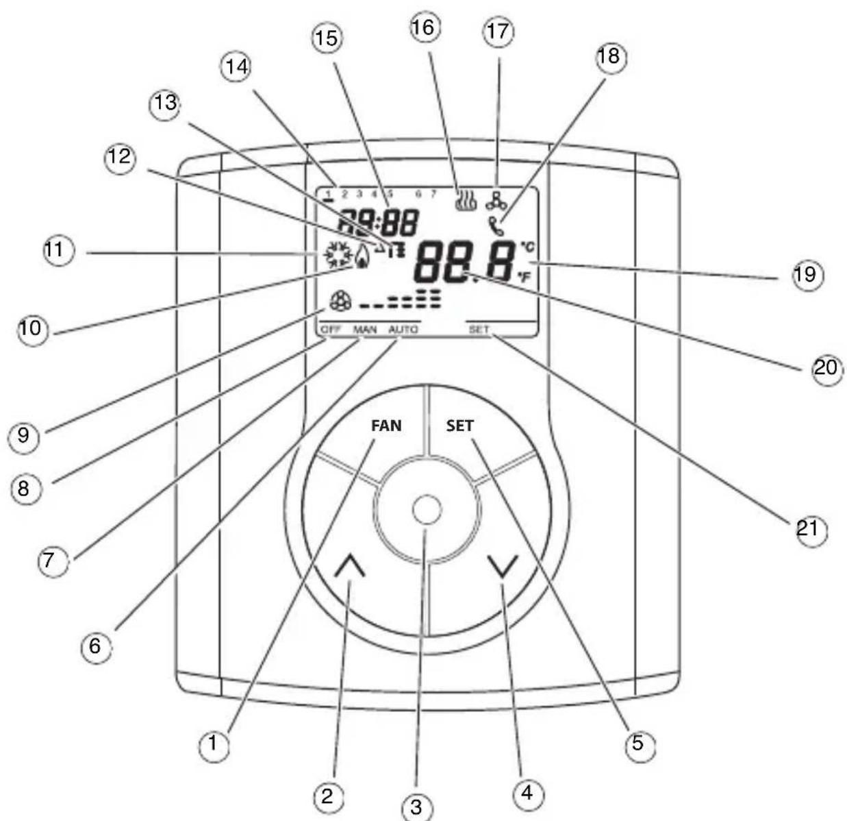
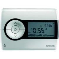
Position of the control keys
The thermostat is fitted with a backlit LCD display and 5 control buttons which are always accessible.
GENERAL DESCRIPTION
Control description
CONTROL BUTTONS Symbol Page
① Fan-coil speed regulation FAN 40
(2) Temperature regulation (+)/select parameters 50
③ Select operation mode / confirmation 38
(4) Temperature regulation (-)/select parameters 50
(5) Setting parameters SET 40
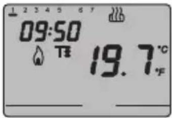
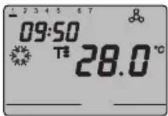
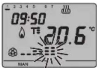
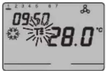
DISPLAY SIGNALS
6 Auto operation mode for the connected fan coil AUTO
7 Manual operation mode for the connected fan coil MAN
8 Thermostat in operation mode OFF OFF
Operation mode speed OFF fan coil ON speed 1 speed 2 speed 3
10 Activation of heating
11 Activation of air-conditioning
12 Thermal differential
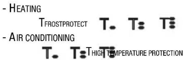
13 Temperature set-point - Operation mode T. Te T
Day of the week
15Clock
Heating function
Air conditioning function
18 Activation by remote control
19 Temperature unit of measurement irc C / irc F
20 Ambient temperature measured
21 Setting parameters SET
Control modes
The thermostat can be set to 2 different control modes:
- Slave: the function depends on the device configured as Master (for instance the Easy EIB timer-thermostat GW 10 761), that set the thermostat operation type and mode. In this function mode the thermostat uses the set-point values that are set locally. It is possible to change the set temperature set-point (max variation ± 3ircC ), whilst it is not possible to change the operation mode. The modified set-point will remain valid until the Master device sends a new operation mode.
- Stand alone: The thermostat operation type and mode are set locally. The operation status does not depend on any other device in Stand-alone mode it is possible to vary the set-point at will and enable the thermostat to receive remote commands from other devices, such as for instance a button or the EIB Easy GSM remote control unit GW 90 861.
Operation mode
The thermostat foresees 4 different operation modes:
ECONOMY
PRECOMFORT
COMFORT
- OFF-FROSTPROTECT/HIGH TEMPERATURE PROTECTION
In the STAND ALONE control mode use the key to switch from one mode to another. In the SLAVE control mode the key is not enabled, as the operation mode is set on the device configured as Master.
In the economy, precomfort and comfort operation modes the timer-thermostat permanently uses the corresponding temperature set-points. The current ambient temperature and the symbol ,T. T: o appear on the screen.
GENERAL DESCRIPTION
T. T: MEANINGS
| Symbol | Heating Air conditioning | |||
| Set point | Operation mode | Set point | Operation mode | |
| Tc | TECONOMY Economy | TCOMFORT Comfort | ||
| Tc | TPRECOMFORT | Precomfort | TPRECOMFORT | Precomfort |
| Tc | TCOMFORT Comfort | TECONOMY Economy | ||
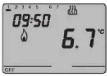
The frostprotect operation is only enabled in heating operation mode, when the thermal regulation system is OFF. In this case the thermostat uses the set frostprotect temperature set-point, re-starting the heating system only when the ambient temperature decreases below T FROSTPROTECT.
The message "OFF" and the measured ambient temperature are displayed on the screen.
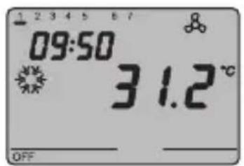
The high-temperature protection operation is only enabled in air-conditioning mode, when the thermal regulation system is OFF.
In this case the thermostat uses the set high-temperature set-point, re-starting the air-conditioning system only when the ambient temperature exceeds the T HIGH TEMPERATURE PROTECTION
The message "OFF" and the measured ambient temperature are displayed on the screen.
USER INSTRUCTIONS
The activation of the heating or air-conditioning operations are indicated as followed:
Heating
The symbol indicates that the activation command has been sent to the actuator which controls the boiler or the zone electro-valve. If the thermostat does not receive confirmation from the actuator that the same has been activated, the symbol starts to flash.
Subsequently, the thermostat sends the activation command again, at one minute intervals, until it receives a positive response.
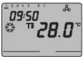
Air conditioning
The symbol indicates that the activation command has been sent to the actuator which controls the air-conditioner or the zone electrovalve. If the thermostat does not receive confirmation from the actuator that the same has been activated, the symbol starts to flash. Subsequently, the thermostat sends the activation command again, at one minute intervals, until it receives a positive response.
Operation with fan-coil control activated
The symbol appears on the display if the fan-coil control is activated in the parameter settings.
Press the FAN key repeatedly to adjust the fan-coil speed or set the AUTO mode option, where the fan-coil speed is automatically regulated according to the difference between the set-point set on the device and the current temperature. The fan coil speed indicator flashes when the fan is running.
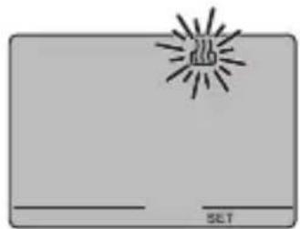
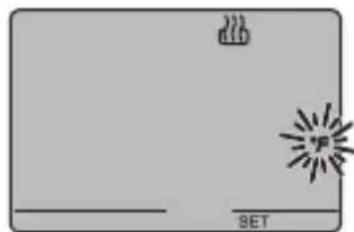
Setting parameters
To set the thermostat parameters, press the SET key.
The word SET appears on the display and the symbol of the set operation type (heating or air-conditioning) starts to flash.
USER INSTRUCTIONS
It is possible to set the following parameters:
| Operation type (heating/air conditioning) |
| Day of the week |
| Hour |
| Minutes |
| Temperature unit of measurement |
According to the operation type, it is now possible to sequentially modify:
| Heating Air conditioning | |
| P01heat - Set Point P01cond - Set Point | T- |
| P02heat - Set Point P02cond - Set Point | T: |
| P03heat - Set Point P03cond - Set Point | T: |
| P04heat - Set Point TFROSTPROTECT | P04cond - Set Point THIGH TEMPERATURE PROTECTION |
| P05 - Control logic P05 - Control logic | |
| P06 - Cycle time P06 - Cycle time | |
| P07 - PWM regulation differential value | P07 - PWM regulation differential value |
| P08 - ON/OFF regulation differential value | P08 - ON/OFF regulation differential value |
| P09 - Control mode P09 - Control mode | |
| P10 - Enable remote control P10 - Enable | remote control |
To scroll the sequence, confirming the values displayed on the screen, press the key until you reach the parameter you want to change.
Press the SET key again to exit the parameter setting procedure or it will exit automatically after a 30" time-out.
It is necessary to perform both sequences to set the heating and air-conditioning parameters (in the second sequence it is possible to confirm the parameters which are the same, and just change the specific ones).
USER INSTRUCTIONS
Selecting heating/air conditioning
When the symbol blinks it is possible to select the operation type using the keys.
Press the key within 30 seconds to confirm the selection.
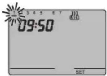
Setting the day of the week
When the day of week bar is blinking, select the current day using the Keys.
(Monday=1, Tuesday=2, Sunday=7)
Press the key within 30 seconds to confirm the value set.
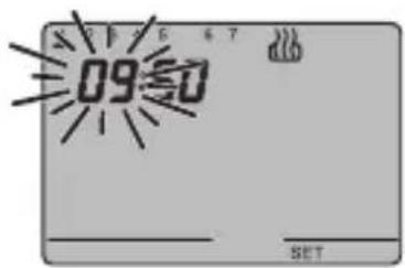
Setting the hour
When the hour figures blink, set the hour using the keys.
Press the key within 30 seconds to confirm the value set.
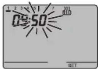
Setting the minutes
When the minutes figures blink, set the minutes using the keys.
Press the key within 30 seconds to confirm the value set.
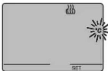
Setting the temperature unit of measurement
When the temperature symbols irc C or ircF starts to blink, select the temperature unit of measurement using the keys.
Press the key within 30 seconds to confirm the value set.
USER INSTRUCTIONS
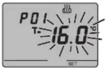
P01heat - Set Point setting (heating)
The temperature value starts to blink when the, T. symbol appears. Regulate the T value (T ECONOMY) using the keys.
Press the key within 30 seconds to confirm the value set.
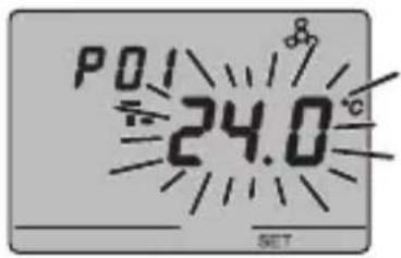
P01cond-Set Point Setting (air conditioning)
The temperature value starts to blink when the, symbol appears. Regulate the (Tcormort) using the keys.
Press the key within 30 seconds to confirm the value set.
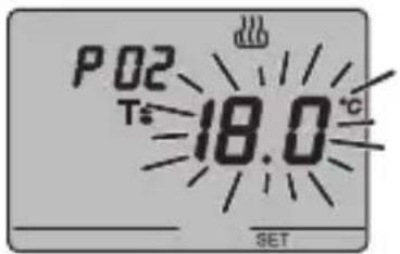
P02heat - Set Point setting (heating)
The temperature value starts to blink when the, T symbol appears. Regulate the value (TPRECOMFORT) using the keys.
Press the key within 30 seconds to confirm the value set.
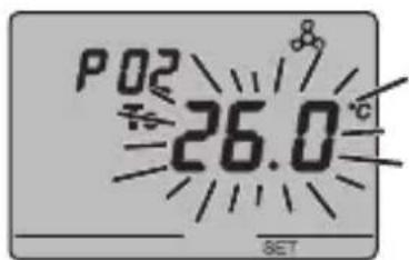
P02cond - Set Point Setting (air conditioning)
The temperature value starts to blink when the T symbol appears. Regulate the T:TPRECOMFORT) value (Tprecomfort) using the keys. Press the key within 30 seconds to confirm the value set.
USERINSTRUCTIONS
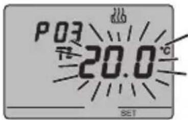
P03heat - Set Point setting (heating)
The temperature value starts to blink when the symbol appears. Regulate the COMFORT) using the keys. Press the key within 30 seconds to confirm the value set.
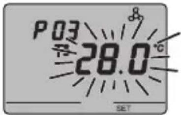
P03cond - Set Point Setting (air conditioning)
The temperature value starts to blink when the, T3 symbol appears. Regulate the (TT3 ECONOMY) using the keys.
Press the key within 30 seconds to confirm the value set.
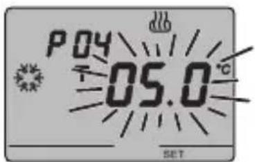
P04heat - set frost-protect temperature value
The temperature value starts to blink when the, il
valore di temperatura inizia a lampeggiare. Regulate the
frost-protect temperature value using the keys. Press the key within 30 seconds to confirm the
value set.
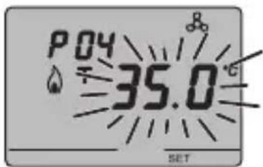
P04cond - Set high temperature protection value The temperature value starts to blink when the, symbol appears. Regulate the high temperature protection value using the keys.
Press the key within 30 seconds to confirm the value set.
WARNING!
The set-point values have the following limits:
USER INSTRUCTIONS
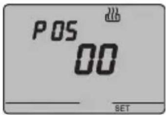
P05 - Control logic
When the P05 code appears on the screen, set the thermal regulation control logic using the keys.
(00 = 2 point control, 01 = proportional control (PWM),
02 = fan coil control)
Press the key within 30 seconds to confirm the value set. It is possible to set different control logics for the heating and air-conditioning operations.
If you select a 2 point control or the fan-coil control, move on to point P08, for proportional control move to point P06.
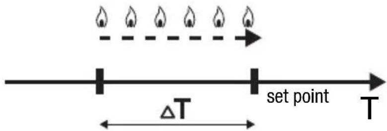
2 POINT CONTROL
The thermal regulation system is switched off when the ambient temperature is equal to the set point, and is switched back on when:
- the temperature is equal to or lower than the set point
- forTheating;
- the temperature is equal to or higher than the set point + for air-conditioning.
The diagrams below show the two function types. HEATING
AIR CONDITIONING
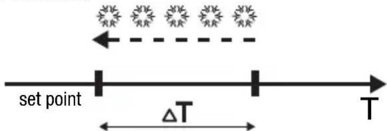
To avoid continuous switchings, the thermostat will wait for up to 2 minutes before sending the activation command to the actuator that controls the thermal regulation system.
USER INSTRUCTIONS
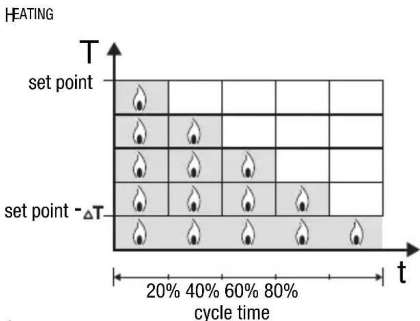
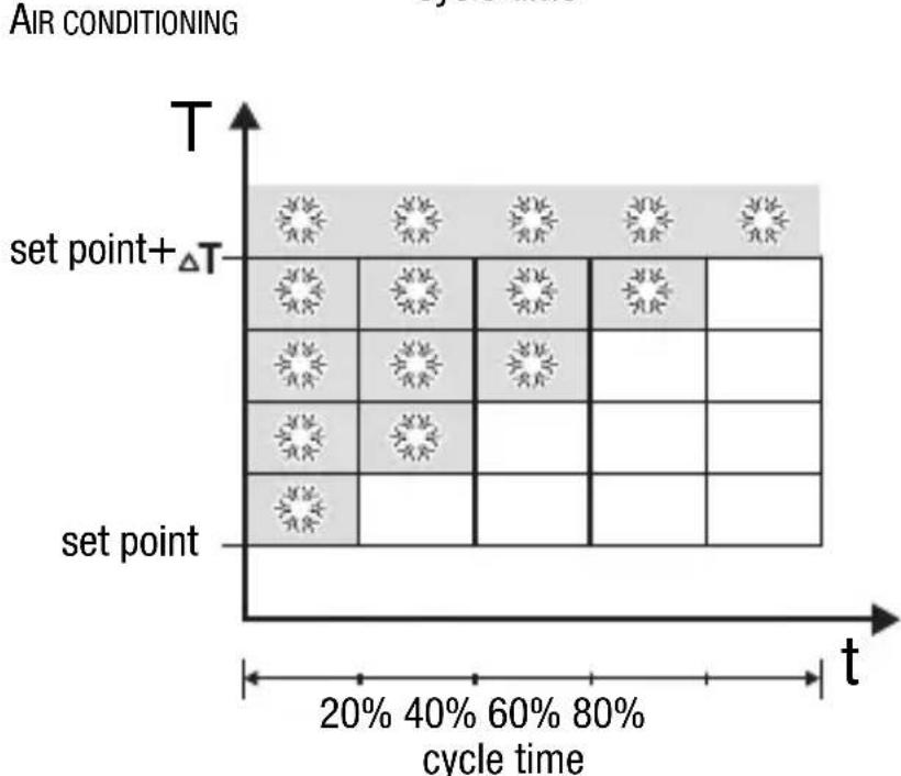
PROPORTIONAL CONTROL (PWM)
The proportional channel (from set point to set point ΔT for heating, from set point to set point + for air-conditioning) is divided into four equal zones. At the end of each cycle time, the thermostat controls the ambient temperature and, according to the differences recorded, it modulates the proportion of the ON and OFF commands transmitted during the cycle time. The diagrams below show the behaviour of the proportional control in heating and air-conditioning operations.
USER INSTRUCTIONS
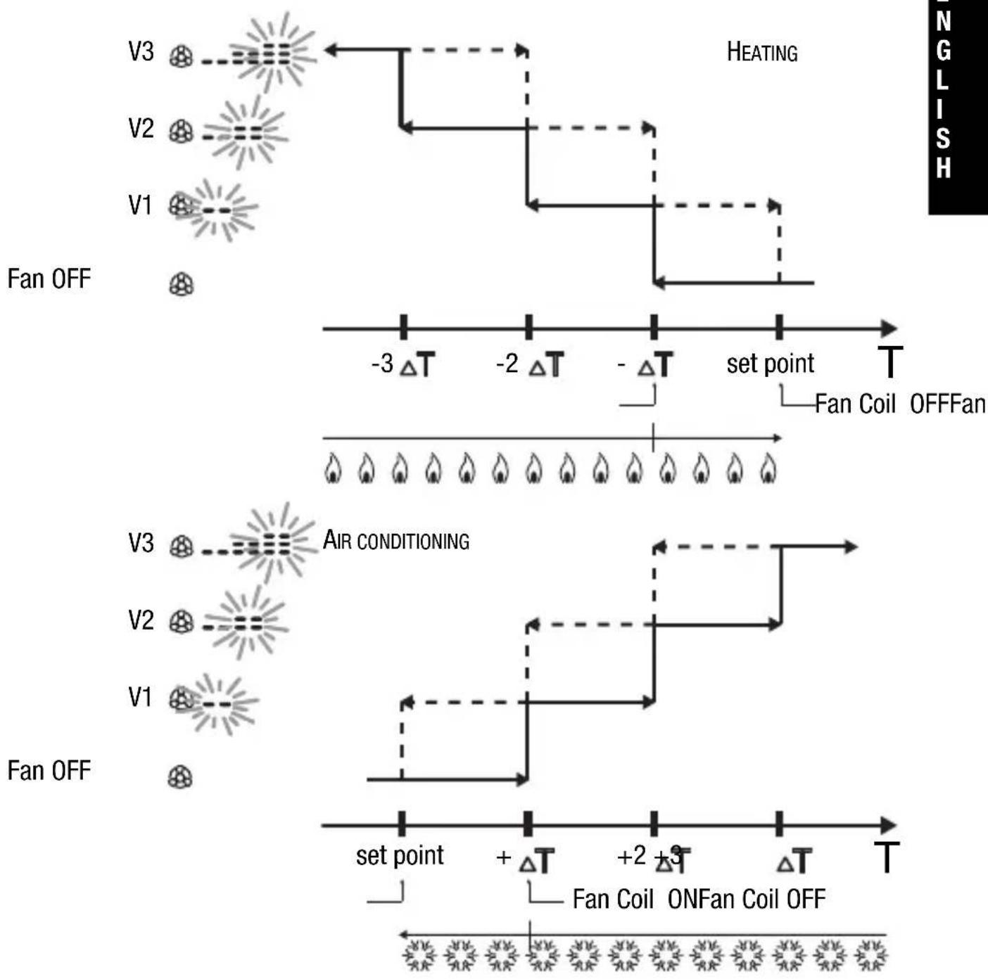
FAN COIL CONTROL
When the temperature reaches the set point value- ΔT (in heating) or set point + (in air-conditioning) an ON message is sent to activate the fan coil for the selected operation type, and an ON message to switch on the fan coil at speed V1.
At set point-2 (in heat.) or set point +2 (in air-cond.) speed V2 is activated, at set point-3 (in heat.) or set point+3 (in air-cond.) speed V3 is activated.
USERINSTRUCTIONS
To avoid continuous switchings, the thermostat will wait for up to 2 minutes before sending the activation command to the actuator that controls the thermal regulation system or to the actuator channels that control the fan coil speed.
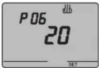
P06 - Setting the cycle time
When the P06 code appears on the screen, set the cycle time using the keys.
The values available are as follows: 5, 10, 20, 30, 40, 50, 60 minutes.
It is possible to set different cycle times for the heating and air-conditioning operations. Press the key within 30 seconds to confirm the value set.
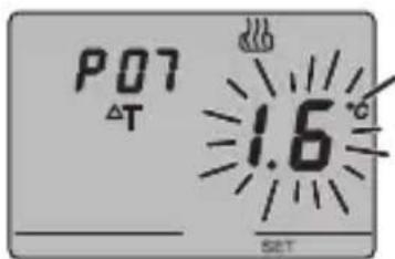
P07 - Setting the PWM regulation differential value
When the P07 code appears on the screen, set the PMW regulation differential value using the keys.
It is possible to set different PWM values for the heating and air-conditioning operations.
Press the key within 30 seconds to confirm the value set.
Move on to point P09.
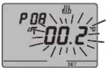
P08 - Setting the regulation differential for 2 point or fan coil control
When the symbol appears on the screen, set the regulation differential time using the keys.
Press the key within 30 seconds to confirm the value set.
The regulation differential is the deviance between the set-point setting and the actual activation temperature. It is possible to set different regulation differentials for the heating and air-conditioning operations.
It is recommended to retain the preset values except in special situations.
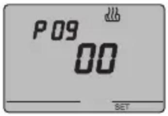
P09 - Setting the control mode
When the P09 code appears on the screen, set the thermostat control mode using the keys. (00 = SLAVE, 01 = STAND ALONE)
For further information, please refer to the Control Mode paragraph.
If the SLAVE mode has been selected, the programming phase has been concluded. Press the SET key to return to normal operation mode.
If the STAND ALONE mode has been selected, move onto point P10.
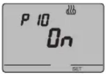
P10 - Enabling remote controls
When the P10 code appears on the screen, enable or disable remote controls using the keys. (OFF = remote controls disabled, ON = remote controls enabled)
The symbol on the display indicates that this option is enabled.
When the remote controls option is enabled it is possible to remotely set the operation type and mode, for instance using the EIB Easy GSM remote control unit (GW 90 861).
The programming phase is now complete. Press the SET key to return to normal operation mode.
USER INSTRUCTIONS
Temporary temperature forcing
It is possible to temporarily force the active temperature set point in Economy, Precomfort and Comfort operation modes by using the keys to set the required value. Confirm the value by pressing the key or waiting for 5 seconds.
The Tor flash on the display to indicate that the forcing is enabled.
If it is in SLAVE control mode, the variation in the temperature set-point is limited to ± 3ircC and remains active until it receives a new mode command from the Master device.
Reset and restore of default settings
Press the FAN and SET keys together for 2 seconds, when the device is powered by the bus, to reset the thermostat.
Warning: all the previously set parameters will be cancelled.
When it is turned back on, the thermostat will use the default factory settings. The thermostat goes into heating in OFF mode.
Preset parameters
Day of the week 1: Monday
Hour 00:00
Heating temperature set-point T1 16 °C
T2 18°C
T3 20irc C
TFROSTPROTECT 5ircC
Air-conditioning temperature set-point T1 24ircC
T2 26 °C
T3 28°C
THIGH TEMPERATURE PROTECTION 35ircC
Temperature unit of measurement irc C
Control logic 2 points
Differential regulation Heating 0.2ircC
for 2 point control Air conditioning 0.5ircC
Differential regulation for proportional control 1.6 °C
Cycle time 20 minutes
Control mode Slave
USER INSTRUCTIONS
Behaviour on the failure and reinstatement of the bus power supply
When the bus power supply fails, the device performs no actions.
The time and date are maintained by the buffer power system (rechargeable battery) whilst all the other settings are saved to a non-volatile memory.
When the power is supplied by battery only, the device has an autonomy of 36 hours in the following conditions:
- display time active;
measure and temperature display not active (dashes are displayed); - backlighting not active;
- front keys are not enabled (except for the simultaneous pressing of FAN and SET).
When there is no bus power the simultaneous pressing of FAN and SET for 2 seconds will cause the rechargeable battery to disconnect inside the device.
This function is used to conserve the efficiency of the battery when the device is not used for a long period. The battery is then automatically reconnected when the device receives power from the bus. The set programs are not lost when there is a failure in the bus connection or when the battery is disconnected.
The device is in full operation mode within a maximum of 5 seconds from reinstatement of the bus power supply.
If the buffer power (rechargeable battery) is absent or disconnected, the thermostat will restart in OFF mode when the bus power is reinstated.
USER INSTRUCTIONS
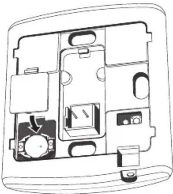
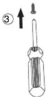
Replacing the battery
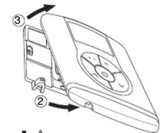
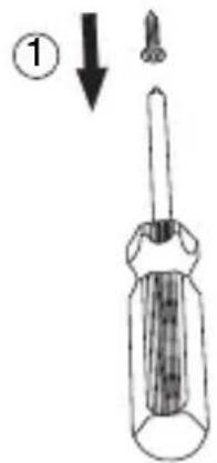
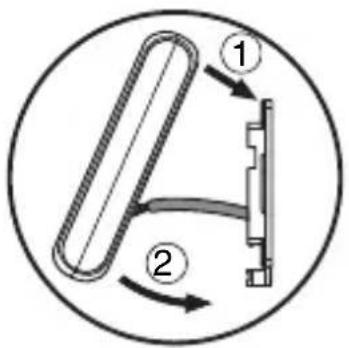
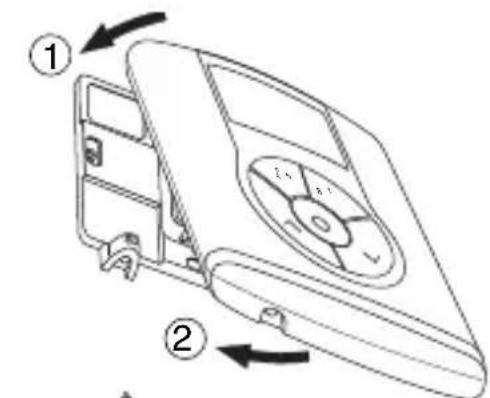
Remove the fastener screws which are under the device, and remove the thermostat from the support base, as seen in the figure below.
Remove the battery holder cover and replace the rechargeable battery with one of the same type (ML1220), paying attention to the direction of the poles.
USER INSTRUCTIONS
Replace the thermostat in the support base, as seen in the figure below, and replace the screws under the device.

WARNING:
- If the thermostat was not powered by the bus whilst replacing the battery, update the time and date.
- Never throw the battery into a fire.
- The battery is a special waste product and therefore it must be disposed of according to the laws in force and taken to a special collection centre.

Cleaning the thermostat
Use a dry cloth to clean the thermostat.
INSTALLATION INSTRUCTIONS

WARNING: the installation of the device must be exclusively done by qualified personnel, following the regulations in force and the guidelines for KNX/EIB installations.
Correct installation position
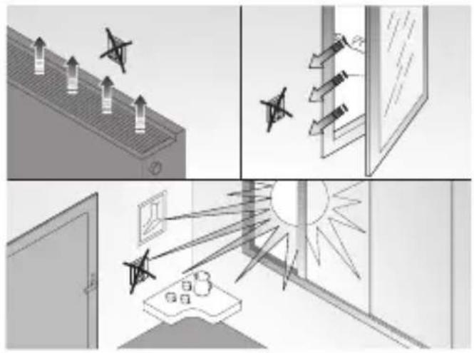
In order for the thermostat to take correct readings of the ambient temperature, it must not be installed in an alcove, near a door or window, next to radiators or air conditioner units and must not be placed in direct sunlight or in draughty areas.
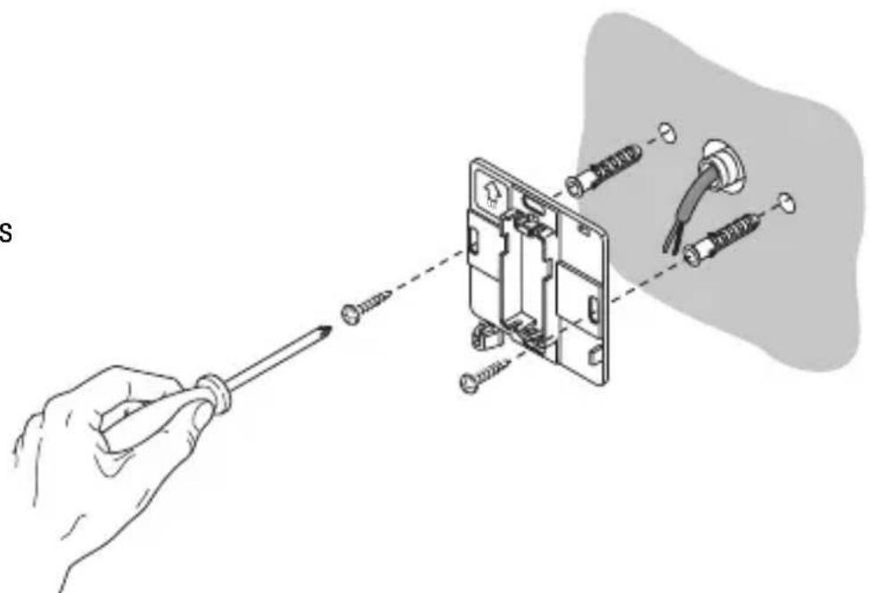
Assembly of the support base
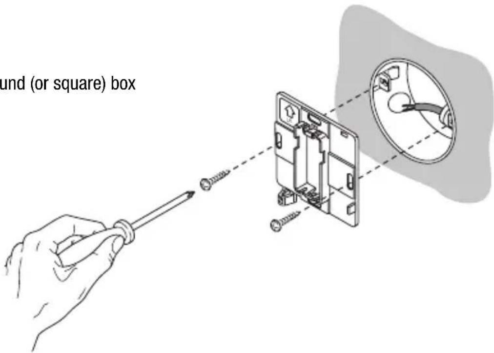
The support base should be positioned at 160 cm from the ground and can be mounted on the wall, using dowels, or on top of a 2-place round or square box (60 mm hole distance).
Mounting with dowels
INSTALLATION INSTRUCTIONS
Mounting on a round (or square) box
Warnings for KNX/EIB installations
- The length of the bus line between the Easy thermostat and the power supply unit must not exceed 350 metres.
- The length of the bus line between the Easy thermostat and the most distant KNX/EIB device must not exceed 700 metres.
- If possible do not create ring circuits so as to prevent undesirable signals and overloads.
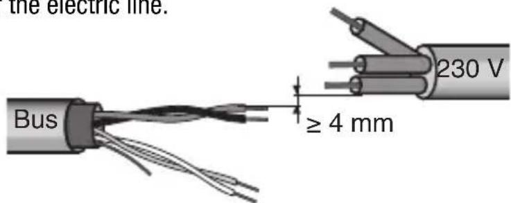
- Keep a distance of at least 4mm between the individually insulated cables of the bus line and those of the electric line.
- Do not damage the electrical continuity conductor of the shielding.

INSTALLATION INSTRUCTIONS
WARNING: the unused bus signal cables and the electrical continuity conductor must never touch elements under power or the earth conductor.
Electrical connections
Electrical connections diagram
- Before connecting the KNX/EIB bus, insert the rechargeable buffer memory battery (see Replacing the Battery paragraph).
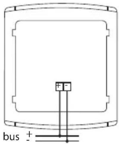
- Connect the bus cable's red wire to the terminal's red connector (+) and the black wire to the black connector (-). Up to 4 bus lines (wires of the same colour in the same connector) can be connected to the bus terminal.
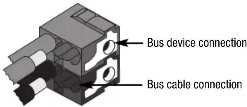
- Insulate the screen, the electrical continuity conductor and the remaining white and yellow wires of the bus cable (should a bus cable with 4 conductors be used), which are not needed.
INSTALLATION INSTRUCTIONS
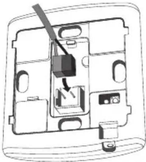
- Insert the bus connector into the special feet of the device. The fastener guides determine the direction it should be inserted.
Initialization with the Easy base unit
-
Power up the device using the bus and wait for 5 seconds until it is in full operation mode.
-
Have the system acquire the device with one of the following procedures:
Automatic acquisition (the device still has the factory settings):
-
select the "Application → New function" or "Application → Edit function" menu in the Easy base unit: the device will be recognized automatically.
-
Manual acquisition (the factory settings have been modified):
-
select the "Application → Search device" menu in the Easy base unit:
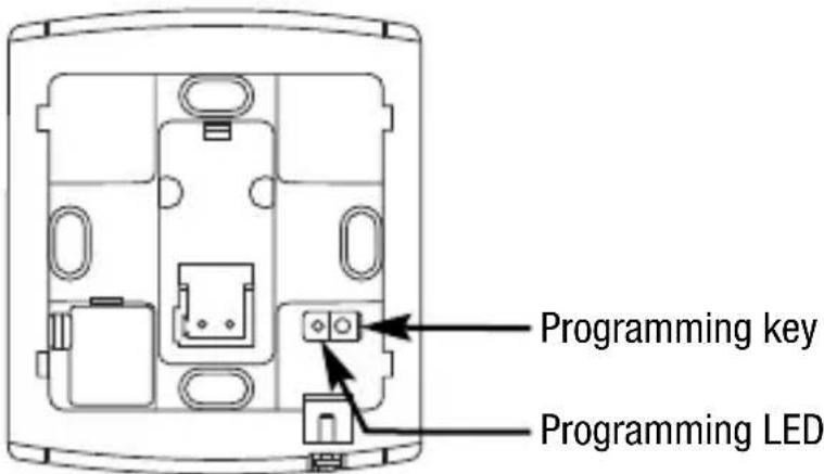
-
briefly press (< 2 seconds) the programming key. The programming LED will light up during the acquisition process.
The device acquired by the Easy base unit will be listed, with the number assigned, in the channels of the "Application → New function" or "Application → Edit function" menus.
INSTALLATION INSTRUCTIONS
Completing installation
Position the thermostat on the support base, as seen in the figure below, and fix it in place using the supplied screws.
Programming with the Easy base unit
Programming the thermostat through the Easy base unit (code GW 90 831).
The thermostat channel to be used in the function that is to be created can be selected at choice:
- Press the , keys together for >5 seconds to enable the programming mode. Use the keys to select the channel you wish to use, then press to confirm: the corresponding channel will be highlighted in the channel list in the "Application → New function" or "Application → Edit function" menu. Press the keys together to exit the programming mode.
- directly from the list of channels of the "Application → New function" or "Application → Edit function" menus.
INSTALLATION INSTRUCTIONS
The channels available in the programming mode are:
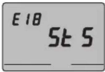
StS (Status)
Used to send to remote devices (for instance the EIB Easy GSM remote control unit - GW 90 861):
- operation type and mode:
- temperature reading (every 15 minutes or each time it changes).
The channel is indicated as "ClimStatus X.2" on the base unit.
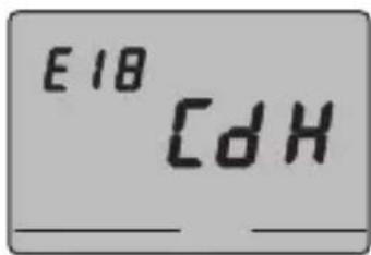
CdH (Command Heating)
Used to send the ON/OFF command to the KNX/EIB actuators that control the heating system.
The channel is indicated as "Cmd+info X.3" on the base unit.
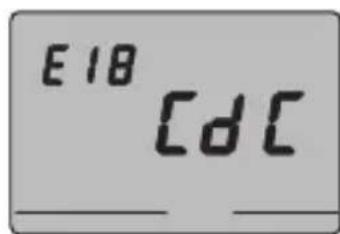
CdC (Command Cooling)
Used to send the ON/OFF command to the KNX/EIB actuators that control the air conditioning system.
The channel is indicated as "Cmd+info X.4" on the base unit.
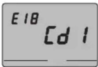
Cd1 (Command 1 - Fan-coil speed)
Used to send the ON/OFF command to the actuator channel that controls speed 1 on the fan coil The channel is indicated as "Cmd+info X.5" on the base unit.
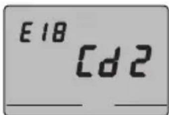
Cd2 (Command 2 - Fan-coil speed 2)
Used to send the ON/OFF command to the actuator channel that controls speed 2 on the fan coil The channel is indicated as "Cmd+info X.6" on the base unit.
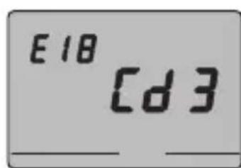
Cd3 (Command 3 - Fan-coil speed 3)
Used to send the ON/OFF command to the actuator channel that controls speed 3 on the fan coil. The channel is indicated as "Cmd+info X.7" on the base unit.
INSTALLATION INSTRUCTIONS
Note. The Cd1, Cd2 and Cd3 channels must only be used when a thermostat is used to control the fan coil.
When creating the above listed functions, it is not necessary to select a base unit function as the link is created automatically.
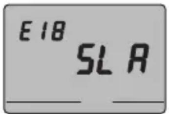
SLA (Slave)
- the thermostat operation type and mode with other KNX/EIB devices from a remote position. Examples of devices which can be used are the EIB EASY GSM remote control unit, the EASY control panel and display, the EASY 4-channel contact interface etc;
- the OFF mode on the thermostat, with priority over all the other commands, if an open window signal is received. When the closed window signal is received, the thermostat returns to its previous operation mode or to the last mode it was in when it received the forced OFF command;
- memorising the scenes, max 8: the thermostat memorises the current operation type, mode and setpoint.
The channel is indicated as "ClimSlave X.1" on the base unit.
If the "slave" channel is combined with the 4-channel contact interface (GW 90 834) the following functions are proposed on the base unit.
| Names of the functions on the Easy base unit | |
| edges Edge management | command (for window contacts) |
| scene Scenario management | command |
| heating mode Thermal regulation commands (mode) | |
Refer to the Easy base unit documentation for further information on the programming procedures.
TECHNICAL DATA
Communication KNX/EIB Bus
Power Supply By KNX/EIB, 29 V dc SELV bus
+1 rechargeable ML1220 3 V battery to update
date and time when there is a bus power failure
Bus current consumption 5 mA
Bus cable KNX/EIB TP1
Control elements 5 front buttons
(timed to user intervention),
1 red programming LED
Temperature display range 0 ÷ +45irc C
Reading elements 1 NTC Sensor
Reading resolution: 0.1ircC
Reading accuracy: ± 0.5ircC to 20ircC intervals
between the next readings: 1 minute
Temperature regulation ranges T frostprotect: +2 ÷ +7irc C
T high temperature protection +30 ÷ +40irc C
Other set points: +5 ÷ +40irc C
Ambient of use Indoors, dry places
Operation temperature -5 ÷ +45irc C
Storage temperature -25÷+70°C
Relative humidity Max 93% (no condensation)
Bus connection Slot in terminal, 2 pin, 1mm
Protection rating IP20
Size (L x H x W) 85 x 95 x 23 mm
Reference standards Low Voltage Directive 2006/95/EC
Electromagnetic Compatibility Directive 89/336/EC
Certifications KNX/EIB
SOMMAIRE
AVERTISSEMENTS GENÉRAUX
page
Contenu de la confection 64
DESCRIPTION GÉNÉRALE
Enbref 65
Programmation minutes
CdH (Command Heating - Commande chauffage)
Communication Bus KNX/EIB
Alimentation Avec bus KNX/EIB, 29 V cc SELV
Cable bus KNX/EIB TP1
Dimension (B x H x P) 85 x 95 x 23 mm
Certifications KNX/EIB
INDICE
CdH (Command Heating - Mando calefaction)
Cable bus KNX/EIB TP1
TFROSTSCHUTZ 5ircC
According to article 9 paragraph 2 of the European Directive 2004/108/EC, the responsible for placing the apparatus on the Community market is:
GEWISS S.p.A Via A. Volta, 1-24069 Cenate Sotto (BG) Italy Tel: +39 035 946 111 Fax: +39 035 945 270 E-mail: qualitymarks@gewiss.com


- USER INSTRUCTIONS
- INSTALLATION INSTRUCTIONS
- GENERAL INFORMATION
- Pack content
- GENERAL DESCRIPTION
- Position of the control keys
- Control description
- CONTROL BUTTONS Symbol Page
- DISPLAY SIGNALS
- Control modes
- Operation mode
- Heating
- Air conditioning
- Operation with fan-coil control activated
- Setting parameters
- Selecting heating/air conditioning
- Setting the day of the week
- Setting the hour
- Setting the minutes
- Setting the temperature unit of measurement
- P01heat - Set Point setting (heating)
- P01cond-Set Point Setting (air conditioning)
- P02heat - Set Point setting (heating)
- P02cond - Set Point Setting (air conditioning)
- USERINSTRUCTIONS
- P03heat - Set Point setting (heating)
- P03cond - Set Point Setting (air conditioning)
- P04heat - set frost-protect temperature value
- WARNING!
- P05 - Control logic
- = fan coil control)
- POINT CONTROL
- PROPORTIONAL CONTROL (PWM)
- FAN COIL CONTROL
- P06 - Setting the cycle time
- P07 - Setting the PWM regulation differential value
- P08 - Setting the regulation differential for 2 point or fan coil control
- P09 - Setting the control mode
- P10 - Enabling remote controls
- Temporary temperature forcing
- Reset and restore of default settings
- Preset parameters
- Behaviour on the failure and reinstatement of the bus power supply
- Replacing the battery
- WARNING:
- Cleaning the thermostat
- Correct installation position
- Assembly of the support base
- Warnings for KNX/EIB installations
- Initialization with the Easy base unit
- Completing installation
- Programming with the Easy base unit
- StS (Status)
- CdH (Command Heating)
- CdC (Command Cooling)
- Cd1 (Command 1 - Fan-coil speed)
- Cd2 (Command 2 - Fan-coil speed 2)
- Cd3 (Command 3 - Fan-coil speed 3)
- SLA (Slave)
- TECHNICAL DATA
- SOMMAIRE
- AVERTISSEMENTS GENÉRAUX
- DESCRIPTION GÉNÉRALE
- Programmation minutes
- CdH (Command Heating - Commande chauffage)
- INDICE
- CdH (Command Heating - Mando calefaction)
Brand : Gewiss
Model : GW14763
Category : Thermostat