OSPSX115SA - Subwoofer KONIG - Free user manual and instructions
Find the device manual for free OSPSX115SA KONIG in PDF.

| Product type | Active subwoofer |
| Brand | Konig |
| Model | OSPSX115SA |
| Frequency response | 40 Hz - 200 Hz |
| SPL (1W/1m) | 102 dB |
| Maximum SPL (at 1m) | 124 dB |
| Input type | Balanced differential |
| Input impedance | 20 kOhms |
| Input protection | Protected level |
| Low-frequency transducer | 15" (386 mm) with 4" (99.2 mm) coil |
| Power amplifier (RMS) | 600 Watts RMS |
| Total harmonic distortion (THD) | < 0.03% |
| Power supply | 120 V/60 Hz (USA) or 230 V/50 Hz (Europe) |
| Cabinet material | 18 mm plywood |
| Dimensions (W x H x D) | 47 x 58 x 60 cm |
| Net weight | 38 kg |
| Main functions | Level adjustment, frequency control (40-200 Hz), clip indicator, low-cut/full-range switch, link output (daisy chain) |
| Maintenance and cleaning | Clean with a dry cloth only; do not use solvents or abrasive products; avoid moisture |
| Safety | Do not open the device; unplug in case of issue; protect from water and moisture |
| Spare parts and repairability | Replaceable standard fuse; keep ventilation openings clean; repair by qualified technician only |
| General information | Design and features subject to change without notice; keep manual and packaging for future reference |
Frequently Asked Questions - OSPSX115SA KONIG
User questions about OSPSX115SA KONIG
0 question about this device. Answer the ones you know or ask your own.
Ask a new question about this device
Download the instructions for your Subwoofer in PDF format for free! Find your manual OSPSX115SA - KONIG and take your electronic device back in hand. On this page are published all the documents necessary for the use of your device. OSPSX115SA by KONIG.
USER MANUAL OSPSX115SA KONIG
natural_image
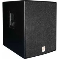
Exterior view of a black multi-tiered electronic device with two speakers and control panels (no text or symbols visible)MANUAL (p. 2)
Active Speaker System 15" + 12"
MODE D'EMPLOI (p. 10)
MANUAL DE USO (p. 22)
Rear Panel Description – Top Speaker
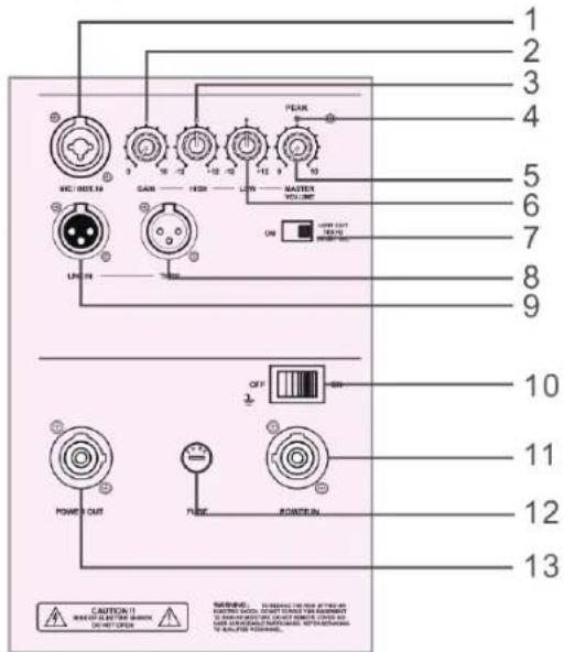
| 01. Mic/line input XLR/1/4 | TRS (tip-ring sleeve) input jack |
| 02. Mic gain Adjust microphone level | |
| 03. EQ control high EQ setting for high frequencies | |
| 04. Peak indicator The peak indicator prevents the amplifier outputs from overdriving the transducers. It lights up when the limiter is activated. It is okay for the peak indicator to blink occasionally, but if it blinks frequently or lights up continuously, turn down the level control. | |
| 05. Master volume This knob adjusts all signal input or mic level. | |
| 06. EQ low control EQ setting for low frequencies | |
| 07. Low cut/full range switch | When the switch is turned off, the top speaker can be used as a full range speaker. |
| 08. Through (full range output) | Male XLR-type connector that produces exactly the same signal that is connected to the main input jack. Use it to daisy-chain several active systems of the same signal source together. |
| 09. Main input Female XLR-type connector that accepts a balanced line-level signal from a mixing console or other signal source. | |
| 10. Power switch | Use this switch to turn the system on and off. Make sure the signal source level control is turned down before you turn it on. |
| 11. Power in | This is where you connect the AC line cord to provide AC power. Plug the line cord into an AC socket properly configured for your particular model. |
| 12. Fuse holder | When a problem occurs in this system, the fuse will cut off the power. To replace, use a standard fuse as specified. |
| 13. Power out AC power out to top system or another active system which is equipped with powercon-3. | |
Rear Panel Description – Sub Speaker
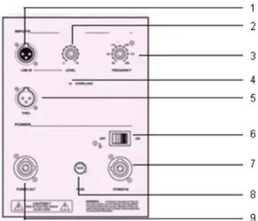
| 01. Full range input Female | XLR-type connector that accepts a balanced line-level signal from a mixing console or other signal source |
| 02. Subwoofer level control | Adjusts the subwoofer level. Use this as a starting point for setting the balance between the subwoofer and the main speaker. |
| 03. Frequency control | With this control you can adjust the bass frequency from 40 Hz to 200 Hz to balance the bass and top speakers. |
| 04. Limit peak indicator | The peak indicator prevents the amplifier outputs from overdriving the transducers. It lights when the limiter is activated. It is okay for the peak indicator to blink occasionally, but if it blinks frequently or lights continuously, turn down the level control. |
| 05. Through (full range output) | Male XLR-type connector that produces exactly the same signal that is connected to the main input jack. Use it to daisy-chain several active systems of the same signal source together. |
| 06. Power switch | Use this switch to turn the system on and off. Make sure the signal source level control is turned down before you turn it on. |
| 07. Power in | This is where you connect the AC line cord to provide AC power. Plug the line cord into an AC socket properly configured for your particular model. |
| 08. Fuse holder | When a problem occurs in this system, the fuse will cut off the power. To replace, use a standard fuse as specified. |
| 09. Power out AC power out | ut to top system or another active system which is equipped with powercon-3. |
TIPS
Do not expose electronic circuitry to moisture!
When the system is placed outdoors, be sure to protect it from rain. Keep drinks and all other liquids well away from the cabinets to protect their electronic components from short circuits.
Ensure that the ducts on the enclosures rear panels are free of dirt and the system is properly ventilated, otherwise electronic components may overheat and suffer damage.
CONNECTIONS
The system has a female XLR input that accepts a balanced line-level signal.
When connecting a balanced signal, be sure it is wired to AES (Audio Engineering Society) standards:
If connecting an unbalanced signal to the system balanced input, be sure that the signal high (hot) connection is wired to pin 2 and the unbalanced ground connection is wired to the low and the ground connections of the balanced input. If there is a ground-loop problem, try connecting the unbalanced ground connection only to the input low connection (pin 3), and leaving the input ground connection disconnected.
The through output connectors allow you to connect more than one bass or other active speaker to your system.
Simply plug the full range input jacks into the first speaker, and patch that speaker through jacks to the next speaker as input jacks, and so on, daisy-chaining multiple speakers. The through jack is wired straight from the full range input connector (there is no electronic circuitry between), so the signal coming out of the through jack is exactly the same as the signal going in.
PLACEMENT
The bass system is designed to sit on the floor.
Never attempt to suspend the system by its handles. As with all electrical components, protect the system from exposure to moisture.
If you are setting the system up outdoors, make sure they are covered if you expect rain.
AC POWER
Be sure the system is plugged into an outlet that is able to supply the correct voltage specifically for your model. Also be sure that the electrical service can supply enough amperage for all the components connected to it. We recommend that a strong supply of AC power is used because the amplifiers place high current demands on the AC line.
Poor bass performance is often caused by a week AC supply to the amplifiers. Never remove the ground pin on the power cord of the bass or any other component.
SPECIFICATION
| OSP-SX110ta | OSP-SX112ta | |
| TOP / 10" FULL RANGE TOP / 12" FULL RANGE | ||
| Cabinet Mid / High Mid / High | ||
| Full range Full range | ||
| Configuration Compact 2-way Compact 2-way | ||
| Nom. Impedance 4 Ohm 4 Ohm | ||
| Rated Power RMS 200 Watt 300 Watt | ||
| SPL 1 w/1 m 100 dB 101 dB | ||
| Frequency Response | (-10 dB) 55-20 KHz | 45-20 KHz |
| Coverage Angle | 90° × 40° | 90° × 40° |
| Crossover Frequency | 3000 Hz | 2000 Hz |
| Voice Coil Protection | PTC | PTC |
| Components High | 1" Driver | 1" Driver |
| Components Mid (Low) | 1x10/200 | 1x12/300 |
| 10" | 12" | |
| Material | Plywood 18mm | Plywood 18mm |
| Finish | Black lacquer | Black lacquer |
| Dimensions (w x h x d cm) | 36x56x38 | 42x62x43 |
| Net Weight (kg) 19 | 25 | |
OSP-SX115sa
OSP-SX118sa
SUB-WOOFER / 15" SUB-WOOFER / 18"
Frequency Range: 40 Hz-200 Hz 40 Hz-200 Hz
SPL 1 w/1 m: 102 dB 102 dB
Max. SPL@1m: 124 dB 124 dB
Input Type: Balanced differential Balanced differential
Input Impedance: 20 K Ohm 20 K Ohm
Input Protection: Level protected Level protected
Low-Frequency Transducer
| Diameter: 15" (386mm) 18" (463mm) | |
| Voice Coil Diameter: 4" (99.2mm) | 4" (99.2mm) |
Low-Frequency Power Amplifier
| Rated Power: | 600 Watt RMS | 600 Watt RMS |
| Rated THD: | <0.03% | <0.03% |
| US | 120 V, 60 Hz | 120 V, 60 Hz |
| Europe | 230 V, 50 Hz | 230 V, 50 Hz |
Cabinet Material Plywood 18mm Plywood 18mm
Dimensions (w x h x d cm) 47x58x60 50x66x60
Net Weight (Kg) 38 44
Safety precautions:

CAUTION
RISK OF ELECTRIC SHOCK DO NOT OPEN

To reduce risk of electric shock, this product should ONLY be opened by an authorized technician when service is required. Disconnect the product from mains and other equipment if a problem should occur. Do not expose the product to water or moisture.
Maintenance:
Clean only with a dry cloth. Do not use cleaning solvents or abrasives.
Warranty:
No guarantee or liability can be accepted for any changes and modifications of the product or damage caused due to incorrect use of this product.
General:
Designs and specifications are subject to change without notice.
All logos brands and product names are trademarks or registered trademarks of their respective holders and are hereby recognized as such.
Keep this manual and packaging for future reference.
Attention:

This product is marked with this symbol. It means that used electrical and electronic products should not be mixed with general household waste. There is a separate collections system for these products.
DEUTSCH
Afmetingen (BxHxD cm) 36x56x38 42x62x43
Netto gewicht (kg) 19 25
| OSP-SX115sa | OSP-SX118sa | |
| SUB-WOOFER / 15" SUB-WOOFER / 18" | ||
| Frequentiebereik: 40 Hz-200 Hz 40 Hz-200 Hz | ||
| SPL 1 w/1 m: 102 dB 102 dB | ||
| Max. SPL op 1 m afstand: 124 dB 124 dB | ||
| Ingangstype: | Differentieel gebalanceerd | Differentieel gebalanceerd |
| Schijnbare weerstand ingang: | 20 K ohm | 20 K ohm |
| Bescherming ingang: | Niveau beschermd | Niveau beschermd |
| Low-frequency transducer | ||
| Diameter: 15" (386mm) | 18" (463mm) | |
| Voice coil diameter: | 4" (99.2mm) 4" (99.2mm) | |
| Low-frequency power amplifier | ||
| Nominaal vermogen: | 600 watt RMS | 600 watt RMS |
| Nominale THD: | <0.03% | <0.03% |
| Verenigde Staten | 120 V, 60 Hz | 120 V, 60 Hz |
| Europa | 230 V, 50 Hz | 230 V, 50 Hz |
Kabinet materiaal Multiplex 18mm
Multiplex 18mm
Afmetingen (BxHxD cm) 47x58x60 50x66x60
Netto gewicht (kg) 38 44
A HANGFALAK ELHELYEZÉSE
TOP / 10" FULDT OMRÅDE TOP / 12" FULDT OMRÅDE