IR Control Pro 8 - Receiver MARMITEK - Free user manual and instructions
Find the device manual for free IR Control Pro 8 MARMITEK in PDF.
User questions about IR Control Pro 8 MARMITEK
0 question about this device. Answer the ones you know or ask your own.
Ask a new question about this device
Download the instructions for your Receiver in PDF format for free! Find your manual IR Control Pro 8 - MARMITEK and take your electronic device back in hand. On this page are published all the documents necessary for the use of your device. IR Control Pro 8 by MARMITEK.
USER MANUAL IR Control Pro 8 MARMITEK
- To prevent short circuits, this product should only be used inside and only in dry spaces. Do not expose the components to rain or moisture. Do not use the product close to a bath, swimming pool etc.
- Do not expose the components of your systems to extremely high temperatures or bright light sources.
- In case of improper usage or if you have altered and repaired the product yourself, all guarantees expire. Marmitek does not accept responsibility in the case of improper usage of the product or when the product is used for purposes other than specified. Marmitek does not accept responsibility for additional damage other than covered by the legal product responsibility.
- Do not open the product: the device may contain live parts. The product should only be repaired or serviced by a qualified repairman.
- Only connect the adapter to the mains after checking whether the mains voltage is the same as the values on the identification tags. Never connect an adapter when it is damaged. In that case, contact your supplier.
- This product is not a toy. Keep out of reach of children.
TABLE OF CONTENTS
INTRODUCTION 3
- OPERATION 3
- CONTENTS OF THE PACKAGE 4
- INSTALLATION 4
- FREQUENTLY ASKED QUESTIONS 6
- TECHNICAL DATA 7
- OPTIONAL ACCESSORIES 8
INTRODUCTION
Congratulated on buying the Marmitek Ir Control Pro 8. With it you can extend the IR (infrared) signals of remote controls. The IR Control Pro 8 makes it possible to control up to 8 A/V devices while these are in a closed cupboard or when your A/V equipment is out of sight. The IR Control Pro 8 is a universal IR extender set and is exchangeable with several other IR products of Marmitek and many other makes.
1. OPERATION
The IR receiver of the IR Control Pro 8 receives the signal of your remote control and converts it into an electric signal which is relayed to the IR module. Up to 8 IR LEDs can be connected to this module. These IR LEDs make an IR signal of the electrical signal which is received by the IR sensor of your a/V apparatus. All signals of your remote control are relayed one to one to all connected IR LEDs. If the IR receiver receives a signal of your remote control it will light up so that you can check the system if it works properly.
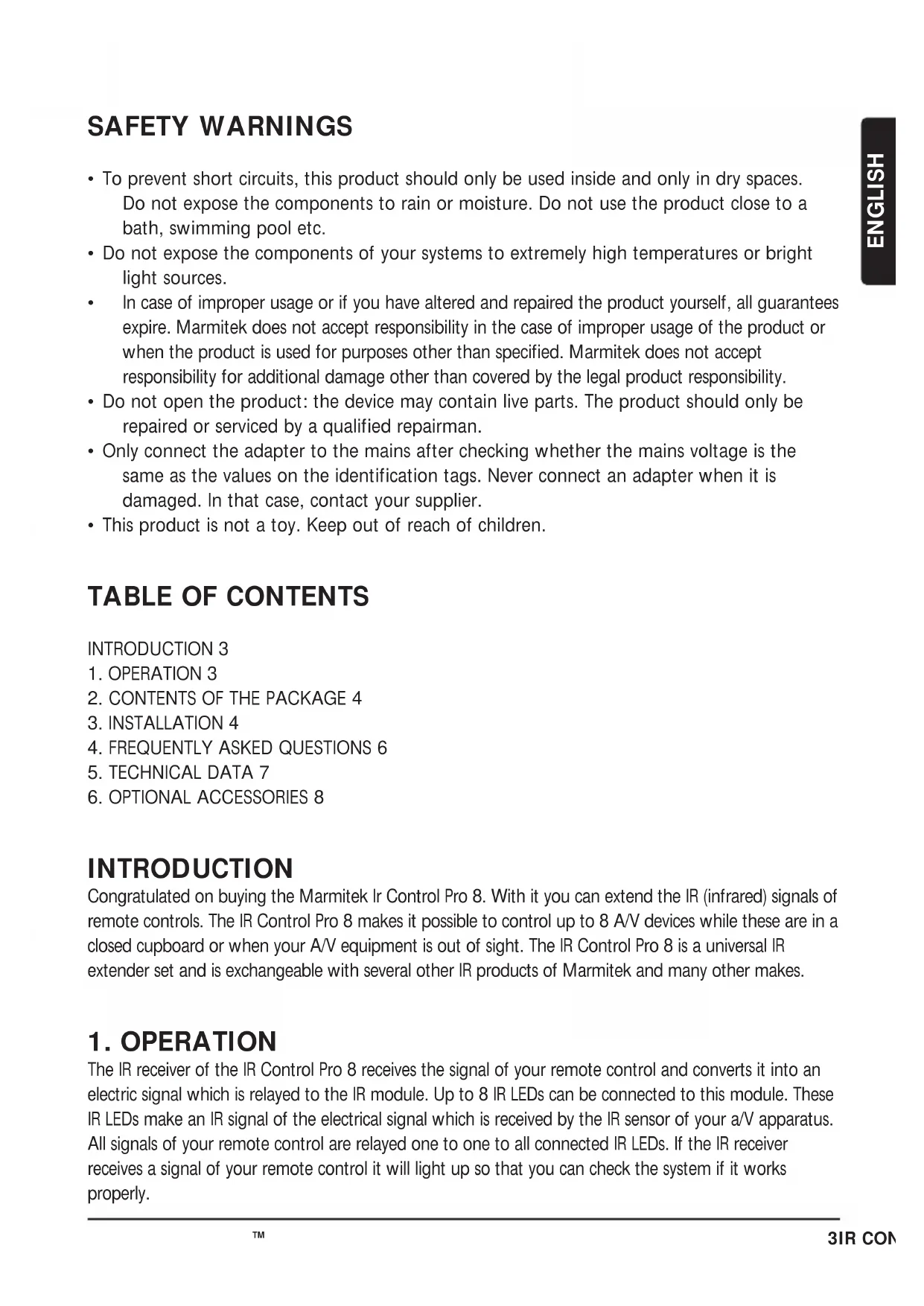
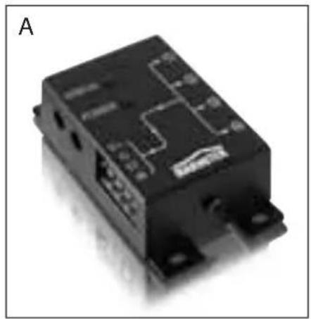
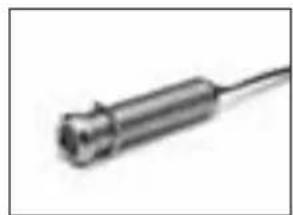
2. CONTENTS OF THE PACKAGE
natural_image
Close-up of a black electronic component with circuit traces and mounting points (no visible text or symbols)
natural_image
Black rectangular object with a long rod, labeled 'B' in the top-left corner (no other text or symbols)
natural_image
Three black sperm cells with rounded tips, arranged horizontally (no text or symbols visible)
natural_image
Black electronic device with attached cable and connector (no visible text or symbols)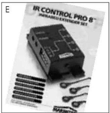
text_image
E IR CONTROL PRO 8™ INRANED EXTENSION SET MARTINA. 1 × IR Module
B. 1 x IR Receiver (with connector)
C. 2 x IR Extension cable with 2 IR LEDs
D. 1 x Power adaptor
E. 1 x Manual
3. INSTALLATION
text_image
1 —— STATUS ● 2 —— POWER ● 3 —— V+ G ST IR 4 5Picture 1
- STATUS Connection for a STATUS power adapter (not supplied)
- POWER Connection for the POWER power adapter (supplied)
- (INPUT) Connection for max. 3 IR receiver(s) (1 x supplied)
- (EMITTERS 1 till 4) Connection for max. 4 IR Extension cables with each 2 IR LEDs. (2 x supplied)
- Fastening holes for stable assembling of the IR Module on a smooth underground.
text_image
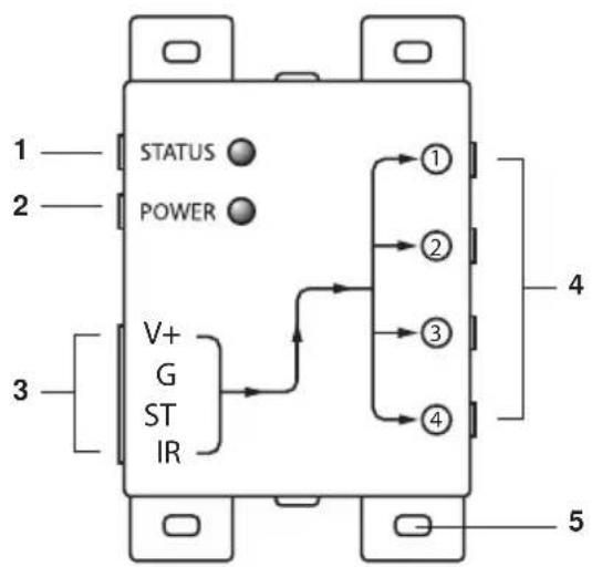
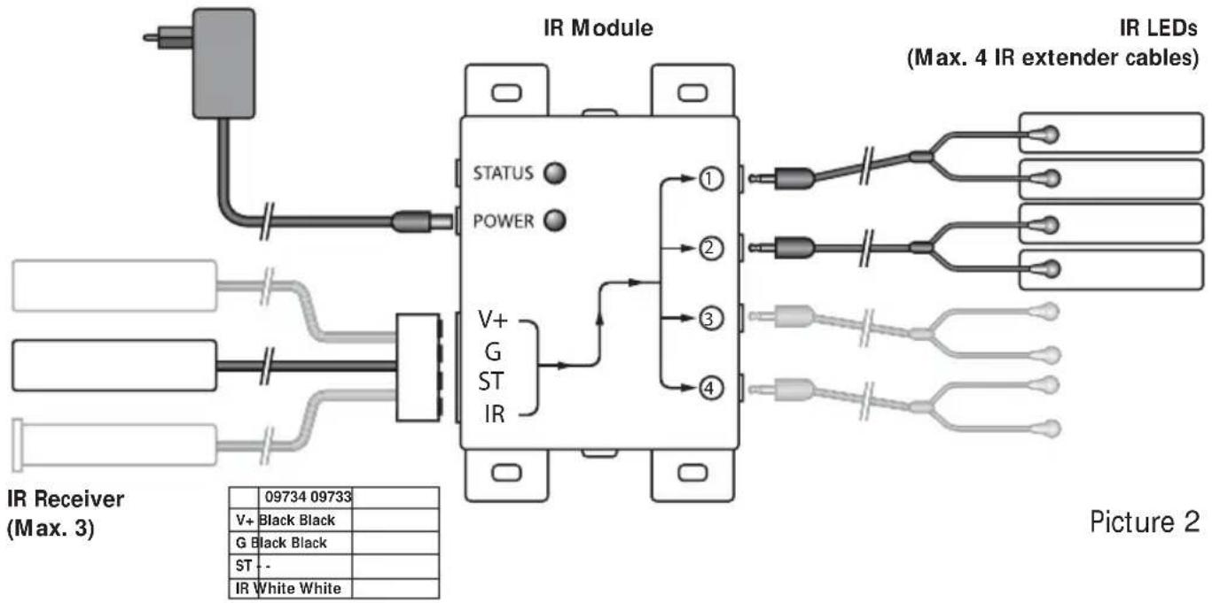
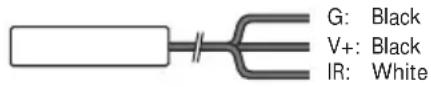
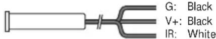
IR Module STATUS POWER V+ G ST IR 1 2 3 4 IR LEDs (Max. 4 IR extender cables) IR Receiver (Max. 3) Picture 2 09734 09733 V+ Black Black G Black Black ST - - IR White WhiteTo check the proper working of the system it is advisable first to test the formation as planned. For this reason connect everything as described as follows but don't fix or screw the components yet.
- Install the IR Module at a place within reach behind or next to your A/V equipment and near a 230V plug (230Volt/50Hz). Take into account the length of the cable of the IR LEDs and make sure that the connections are kept accessible if possible.
- Plug the required IR Extension cables (with the 2 IR LEDs) into the IR Module (Picture 1 nr. 4). A self-adhesive foil is supplied with the IR LEDs. With that you can fasten the IR LEDs to the IR window of your A/V equipment. Note: it's tricky work. First test the position and working of the IR LEDs before fixing them permanently to the IR window of your A/V equipment. Note: If you use only one of the 2 LEDs, then leave the second IR LED unused. Never remove it from the IR extension cable!
- Now connect the IR Receiver to the IR Module, for your convenience the connection clip has been connected to the wiring of the IR Receiver, take care when plugging in of the correct position (nuts up) and colours of the wiring. When you have to disconnect the wiring for instance because a connecting clip won't go through a hole in the furniture, connect afterwards the wiring to the clip according to the connection scheme in Picture 2.
-
Place the supplied IR receiver in such a way that it is visible for your infrared remote control and if possible not in the vicinity of potential sources of disturbance like direct sun light, TL lighting, energy saving lamps etc. The infrared LED indicator on the IR receiver lights up or flashes when it receives an infrared signal. Use the LED indicator to place the IR receiver in the place with the least interference (LED indicator is not activated or only faintly lights up). Because of the supplied self-adhesive strip installation is possible almost everywhere. Experiment for the correct place before you fix the IR receiver definitively. Note: The adhesive strip can cause discoloration on certain surfaces or leave glue remnants by removal.
-
Connect the power adapter to the 'POWER' connection of the IR module and plug the adapter to a wall plug. (230V/50Hz). Check if the 'POWER' LED is on.
TIP:
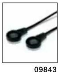
- With the help of the supplied IR Extension cables 4 A/V devices can be controlled with the IR Module, which is simply to be extended to maximal 8 A/V devices with the help of one ore two optional obtainable IR LEDs. (Art. Nr. 09843).
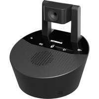
- With the help of an extra IR Receiver you can also control your A/V equipment from another place (if desired you can extend the connection cable of the IR receiver.)
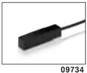
- built-in IR receiver Art. nr. 09733
- built-on IR receiver Art. nr. 09734
STATUS CONNECTION (Power adapter not supplied)
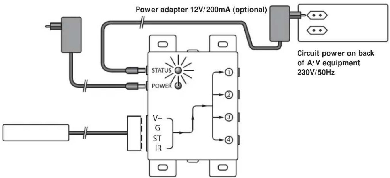
text_image
Power adapter 12V/200mA (optional) Circuit power on back of A/V equipment 230V/50Hz STATUS POWER V+ G ST IR ① ② ③ ④Picture 3
You can send a Power Status signal to the IR module by connecting a Power adapter to this connection (not supplied; 12VDC/200mA), which is switched by the device to be controlled. When the A/V device or contact is switched in a LED will light up in the IR Module so that you can see that the A/V device is switched in. (see picture 3).
4. FREQUENTLY ASKED QUESTIONS
The IR Receiver does not respond to signals of my remote control.
Observe the following directions:
- Check the connections, is the power adapter connected to the correct connection? This must be connected to the 'POWER' connection, the green lamp will burn when the power adapter is plugged in the plug.
-
Both the built-in and the built-on IR Receiver has a reception sensibility of about 10 metres at an opening Angle of 90 degrees. Range is also dependent on the remote control used. The IR reception indication LED in the IR Receiver will light up at reception of an IR signal.
-
The IR Receiver does not work together with some A/V apparatus and models which use a higher IR frequency like for instance Bang&Olufsen (B&O).
- Sometimes it may be that the IR Receiver is troubled by so-called interference (direct sunlight, TL lighting, energy saving lamps etc). In that case you ought to re-direct the IR Receiver a bit for a better result.
Can I use the IR Receiver near a flat screen TV?
Yes, sometimes it may happen that the IR receiver suffers some disturbance from the TV screen. Then move the IR receiver in such a way that it is not in the direct radiation of the TV. It is easy to test. The infrared LED indicator on the IR receiver lights up or flashes when it receives an infrared signal. Use the LED indicator to place the IR receiver in the place with the least interference (LED indicator is not activated or only faintly lights up).
Do you have questions that were not answered in the above mentioned? Then look at www.marmitek.com.
5. TECHNICAL DATA
IR Module
Feed POWER: 230VAC/50Hz, 12VC 500mA (supplied).
Feed STATUS: 12VDC 200mA. Plug, -5.5 mm outside / + 2.1 mm inside (not supplied).
IR LEDs connections: 4 x 3.5 mm jack plug (mono).
IR Receiver connection: 1 Connector for maximal 3 parallel connected receivers.
Dimensions: 85x49x24xmm (fastening points inclusive).
IR receiver built-on
Frequency range: 30-100 KHz.
IR reception range: ± 10 metres.
Length of cable: 2 metres, extendable to max 300 metres (UTP or equivalent).
IR receiver: Reception indication LED.
IR reception angle: 90° (+45°/-45° from centre).
Dimensions receiver bloc: 51x10x8mm.
IR receiver built-in (optional)
Frequency range: 30-100 KHz.
IR reception range: ± 10 metres
Length of cable: 2 metres, extendable to max 300 metres (UTP or equivalent).
IR receiver: Reception indication LED.
IR reception angle: 90^ (+45°/-45° from centre)
Dimensions receiver: Diameter 11.7 mm - Drilling size 12 mm - Length 50 mm
Built-in depth 55 mm - Maximal thickness of material 40 mm.
IR Extension cable
Connection: 3.5mm jack plug
IR LEDs: 2x IR LED
Length of cable: 3 metres (from plug to division 2m, from division to LED 1m).
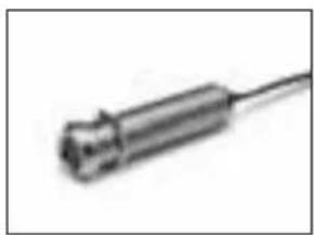
6. OPTIONAL ACCESSORIES
Extra IR receiver
Built-on Art.nr. : 09734
Panel Mount Art.nr.: 09733
With the help of an extra IR Receiver you can also operate your A/V from another room. See for more information www.marmitek.com.
natural_image
Close-up of a black electronic component with a cable, labeled 09734 (no other text or symbols visible)
natural_image
Close-up of a metallic cylindrical electronic component with a coiled cable, labeled 09733 (no other text or symbols visible)Extra IR Extension cable Art.nr.: 09843
With the help of an extra IR extension cable you can operate 2 extra A/V devices. (Extendable to maximal 8 A/V apparatus). See for more information www.marmitek.com.
natural_image
Close-up of two black, rounded objects resembling sensors or probes (no text or symbols visible)Marmitek EasyControl8™ Art.nr.: 09662
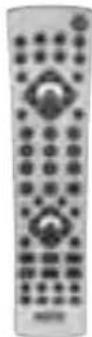
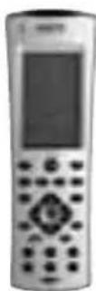
Marmitek EasyTouch35™ Art.nr.: 09664
With both universal remote controls you can control 8 A/V devices: TV, video, DVD, cable, satellite, audio, Marmitek X10 and digital satellite. Through pre-programmed codes and learner function they work always. The EasyTouch35™ is provided with a convenient Touchscreen with pale blue screen lighting. See for more information www.marmitek.com.
0966409662
Environmental Information for Customers in the European Union
European Directive 2002/96/EC requires that the equipment bearing this symbol on the product and/or its packaging must not be disposed of with unsorted municipal waste. The symbol indicates that this product should be disposed of separately from regular household waste streams. It is your responsibility to dispose of this and other electric and electronic equipment via designated collection facilities appointed by the government or local authorities. Correct
disposal and recycling will help prevent potential negative consequences to the environment and human health. For more detailed information about the disposal of your old equipment, please contact your local authorities, waste disposal service, or the shop where you purchased the product.
SICHERHEITSHINWEISE
natural_image
Close-up of a black electronic component with circuit traces and mounting holes (no visible text or symbols)
natural_image
Black rectangular object with a long rod, labeled 'B' in the top-left corner (no other text or symbols)
natural_image
Three black sperm cells with rounded tips, arranged diagonally (no text or symbols visible)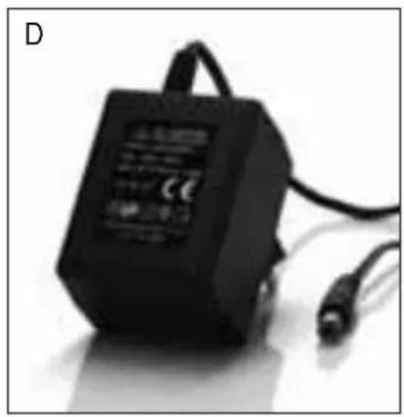
natural_image
Black electronic device with attached cable and connector, labeled 'D' in top-left corner (no visible text or symbols on body)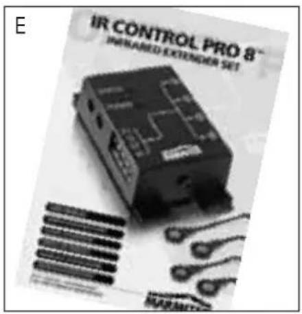
text_image
E IR CONTROL PRO 8™ INRANED EXTENDER SET MARRANTICnatural_image
Close-up of two black electronic components with circular ends, isolated on white background (no text or symbols)09843
natural_image
Close-up of a black electronic component with mounting holes and circuit traces (no visible text or symbols)
natural_image
Black rectangular object with a long rod, labeled 'B' in the top-left corner (no other text or symbols)
natural_image
Three black sperm cells with rounded tips, arranged horizontally (no text or symbols visible)
natural_image
Black electronic device with attached cable and connector (no visible text or symbols)
text_image
E IR CONTROL PRO 8™ INRANED EXTENSION SET MARTINUMAlimentation STATUT: 12VDC 200mA. borne de raccordement,
6. DISPONIBLE EN OPTION
natural_image
Close-up of a black electronic component with a cylindrical body and cable, isolated on white background (no text or symbols)09734

natural_image
Close-up of a metallic cylindrical electronic component with a coiled cable (no visible text or symbols)09733
natural_image
Close-up of two black medical sensors with circular end caps (no text or symbols visible)09843
Marmitek EasyControl8™ Art no.: 09662
Marmitek EasyTouch35™ Art no.: 09664
natural_image
Close-up of a black electronic component with circuit traces and mounting points (no visible text or symbols)
natural_image
Black rectangular object with a long rod, labeled 'B' in the top-left corner (no other text or symbols)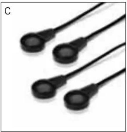
natural_image
Three black sperm cells with rounded tips, arranged horizontally (no text or symbols visible)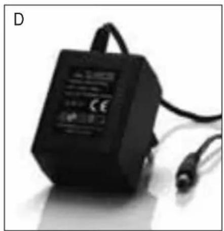
natural_image
Black electronic device with attached cable and connector (no visible text or symbols)
text_image
E IR CONTROL PRO 8 INRANED EXTENSION SET MARTINnatural_image
Close-up of a black rectangular electronic component with a thin cable, isolated on white background (no text or symbols)09734
natural_image
Close-up of a metallic cylindrical electronic component with a coiled cable (no visible text or symbols)09733
natural_image
Close-up of two black medical sensors with circular end caps (no text or symbols visible)09843
Marmitek EasyControl8™ No. de art.: 09662
Marmitek EasyTouch35™ No. de art.: 09664
natural_image
Close-up of a black electronic component with visible traces and mounting holes (no text or symbols)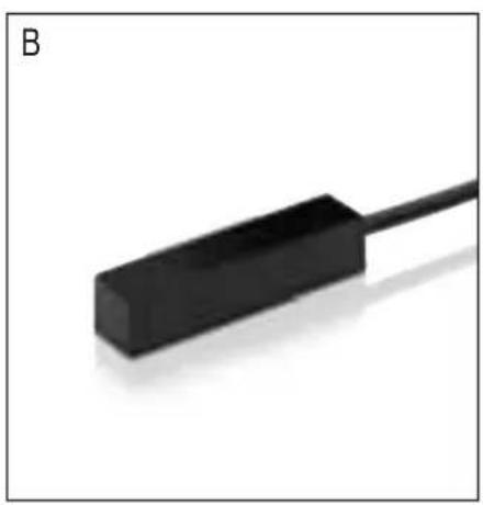
natural_image
Black rectangular object with a long rod, labeled 'B' in the top-left corner (no other text or symbols)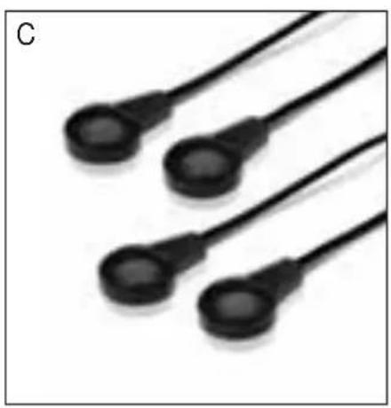
natural_image
Three black sperm cells with rounded tips, arranged horizontally (no text or symbols visible)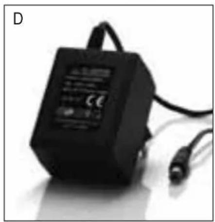
natural_image
Black electronic device with attached cable and connector, labeled 'D' in top-left corner (no visible text or symbols on body)
text_image
E IR CONTROL PRO 8™ IMPIANED EXTENDER SETnatural_image
Close-up of a black rectangular electronic component with a white lead, isolated on white background (no text or symbols visible)09734
natural_image
Close-up of a metallic cylindrical electronic component with a coiled cable (no visible text or symbols)09733
natural_image
Close-up of two black electronic components with leads (no text or symbols visible)09843
Marmitek EasyControl8™ Art. n°: 09662
Marmitek EasyTouch35™ Art. n°: 09664
VEILIGHEIDSWAARSCHUWINGEN
natural_image
Close-up of a black electronic component with circuit traces and mounting holes (no visible text or symbols)
natural_image
Close-up of a black rectangular electronic component with a long cable, labeled 'B' in the top-left corner (no other text or symbols visible)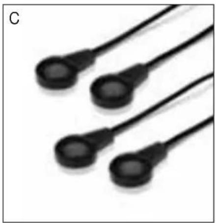
natural_image
Three black sperm cells with rounded tips, arranged horizontally (no text or symbols visible)
natural_image
Black industrial electrical component with attached cable and connector (no visible text or symbols)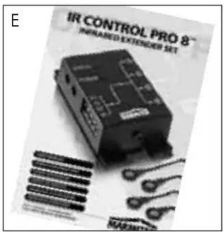
text_image
E IR CONTROL PRO 8™ INPLANED EXTENDER SET MARATHAnatural_image
Close-up of a black electronic component with a white cable, labeled '09734' at the bottom (no other text or symbols visible)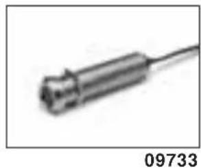
natural_image
Close-up of a metallic cylindrical electronic component with a coiled cable, labeled 09733 (no other text or symbols visible)Extra IR Verlengkabel Artnr.: 09843
natural_image
Close-up of two black, rounded objects resembling sensors or probes (no text or symbols visible)Marmitek EasyControl8™ Artnr.: 09662
Marmitek EasyTouch35™ Artnr.: 09664
natural_image
Two remote control devices shown from different angles, one with a black-and-white pattern and the other with a digital display (no visible text or symbols on the devices themselves)
DECLARATION OF CONFORMITY
Hereby, Marmitek BV, declares that this IR Control Pro8 is in compliance with the essential requirements and other relevant provisions of the following Directives:
DIRECTIVE 2004/108/EC OF THE EUROPEAN PARLIAMENT AND OF THE COUNCIL of 15 December 2004 on the approximation of the laws of the Member States relating to electromagnetic compatibility
Directive 2006/95/EC of the European Parliament and of the Council of 12 December 2006 on the harmonisation of the laws of Member States relating to electrical equipment designed for use within certain voltage limits
Directive 2002/95/EC of the European Parliament and of the Council of 27 January 2003 on the restriction of the use of certain hazardous substances in electrical and electronic equipment
Marmitek is a trademark of Marmidenko B.V. IR Control Pro 8 ^™ is a trademark of Marmitek B.V. All rights reserved.
Copyright and all other proprietary rights in the content (including but not limited to model numbers, software, audio, video, text and photographs) rests with Marmitek B.V. Any use of the Content, but without limitation, distribution, reproduction, modification, display or transmission without the prior written consent of Marmitek is strictly prohibited. All copyright and other proprietary notices shall be retained on all reproductions.