HA30W - Receiver HQ - Free user manual and instructions
Find the device manual for free HA30W HQ in PDF.


User questions about HA30W HQ
0 question about this device. Answer the ones you know or ask your own.
Ask a new question about this device
Download the instructions for your Receiver in PDF format for free! Find your manual HA30W - HQ and take your electronic device back in hand. On this page are published all the documents necessary for the use of your device. HA30W by HQ.
USER MANUAL HA30W HQ
WARNING:THIS APPLIANCE MUST BE EARTHED

IMPORTANT
The wires in the mains lead are coloured in accordance with the following code:
Green and Yellow: Earth (E)
Blue:
Neutral
Brown:Live (L)
As the colours of the wires in the mains lead of this appliance may not correspond with the coloured markings identifying the terminals in your plug proceed as follows:
- The green and yellow coloured wire must be connected to the terminal that is marked by the letter E, marked by the safety earth symbol or coloured green and yellow.
- The blue coloured wire must be connected to the terminal that is marked with the letter N or coloured black.
- The brown coloured wire must be connected to the terminal that is marked with the letter L or coloured red. If a 13 Amp (B.S.1363) plug or any other type of plug is used, a 5 Amp fuse must be fitted either in the plug or at the distribution board.
GENERAL INSTALLATION
DO NOT run microphone cables near mains, data, telephone or 100V line cables.
DO NOT run 100V line cables near data, telephone or other low voltage cables.
DO NOT exceed 90% of the amplifiers output power when using 100V line (speech only).
DO NOT exceed 70% of the amplifiers output power when using 100V line (high level background music).
DO NOT use re-entrant horn loudspeakers for background music unless the loudspeaker has been specifically designed for this purpose.
AVOID jointing the microphone cable, when this is unavoidable make sure a good screened connector is used, e.g. XLR.
ALWAYS use a balanced or floating low impedance microphone terminating into a balanced input on long microphone cable runs.
ALWAYS use a mains grade double insulated cable for the loudspeaker cable runs.
ENSURE that all loudspeakers are in-phase.
ENSURE that there are no short circuits on the loudspeaker line before connecting to the amplifier.
FRONT PANEL
Mixer Amplifier
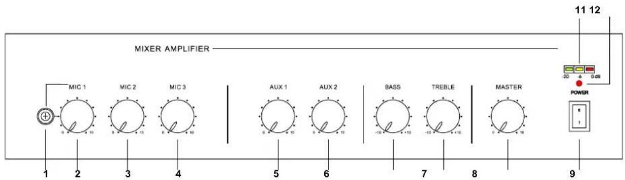
| 1. Mic 1 Input (Phone) 7. Master Tone Control (Bass) | |
| 2. Mic 1 Volume Control 8. Master Tone Control (Treble) | |
| 3. Mic 2 Volume Control 9. Master Volume Control | |
| 4. Mic 3 Volume Control 10.Power On/Off Switch | |
| 5. Aux 1 Volume Control 11.Output Level Indicator LED | |
| 6. Aux 2 Volume Control 12.Power On/Off Indicator LED |
REAR PANEL
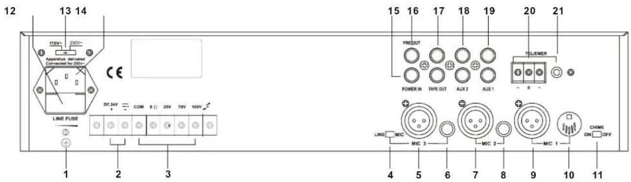
| 1. Earth Connection Screw | 12. AC Fuse Holder |
| 2. DC Power Supply Terminals | 13. Mains Voltage (115V/230V) Selector Switch |
| 3. Loudspeaker Output Terminals | 14. Mains Input Socket |
| 4. Mic3 (Line / Mic) Selector Switch | 15. Power Input (RCA Phono) |
| 5. Mic3 Input (XLR / Balanced) | 16. Pre Output (RCA Phono) |
| 6. Mic3 Input (Phone / Balanced) | 17. Tape Output(2X RCA Phono) |
| 7. Mic2 Input (XLR / Balanced) | 18. Aux2 Input (2X RCA Phono) |
| 8. Mic2 Input (phone / Balanced) | 19. Aux1 Input (2X RCA Phono) |
| 9. Mic1 Input (XLR / Balanced) | 20. TEL / EMER Input Terminals |
| 10. Mic1 Input (DIN / Balanced) | 21. TEL / EMER Input Level Control |
| 11. Chime On/Off switch |
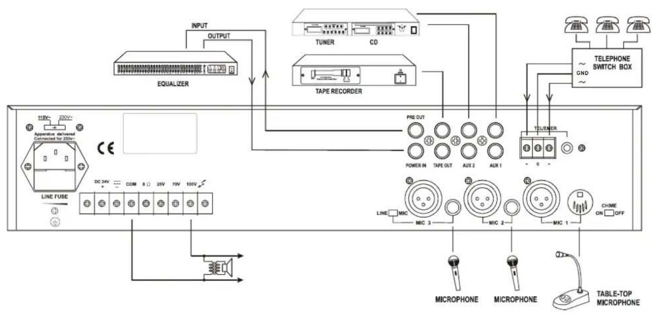
Mains Connection
The supply transformer has been designed for use either 115V AC or 230V AC, selected by slide switch on rear panel. The amplifier is factory set at 230V AC mains voltage.
Battery Connection (24V DC)
When using external batteries, earth the amplifier via the screw terminal because there are high voltages present. Electrical stability of the system is increased by earthing the case.
NOTE: The connection cable must be fitted with an in-line fuse, quick blow type (30W : 5A, 60W : 8A, 120W : 15A). When connecting batteries please ensure correct polarity.
Microphone Connections
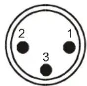
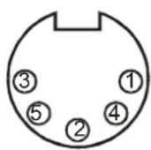
Mic1 input is either a balanced standard 6.35mm stereo jack on front panel or XLR and DIN on the rear panel (With selectable phantom power). Wiring is as follows:
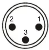
XLR (Balanced Operation)
Pin1 : Screen
Pin2: Signal (live)
Pin3:Signal (return)
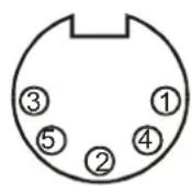
DIN (Balanced operation)
Pin1: Signal (live)
Pin2:GND
Pin3:Signal (return)
Pin4:Priority Control
Pin5:GND
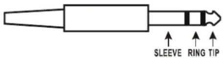
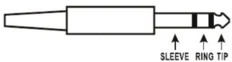
6.35mm Stereo Jack Plug (Balanced operation)
Tip : Signal (live)
Ring: Signal (return)
Sleeve : Screen
Mic1 input has VOX priority which will override Mic2-3 and Aux1-2 input signals but NOT the TEL/EMER input.
Mic1-3 input are XLR,DIN and phone jack with selectable phantom power located on the rear panel and wired as above. The phantom power is factory set and be enabled as follows:
- Remove the power lead from the AC wall socket.
- Remove the top cover.
- Locate the link pins (Marked SW102) on the Printed Circuit Board behind the microphone XLR input socket.
- Connect the black shorting plug to the centre pin and ON position to enable the phantom power.
Chime
Switch on the chime on/off switch on the rear panel and short the pin4, pin5 of DIN socket or short the sleeve and ring of phone plug Mic 1. This will activate the chime function ("Ding-Dong" attention signal preceding a call). The default volume of the chime is pre-set at the factory and is adequate for most applications.
Telephone Connection
This input is for emergency announcements/signals and is not effected by the master volume control. Input level can be set by level control on the rear. The TEL input has the highest priority and will override all other inputs.
Aux Connection
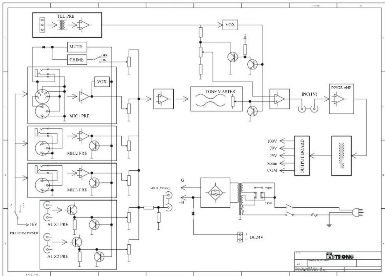
This amplifier provides two auxiliary inputs that may be used for connecting other signal sources such as a radio tuner, CD player or cassette player. The level control operates individually. Turn the control clockwise to increase the volume or anticlockwise to reduce the volume.
The Aux input sockets are standard RCA phono, two sockets are supplied and these are linked together internally. This allows stereo signal sources to be used without the need to obtain a special lead, however you may wish to check with the manufacturer of the signal source to ensure that no damage will result if the left and right output channels are put in parallel.
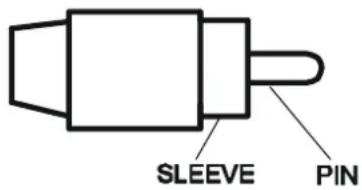
RCA Phono plug connections
Sleeve: Screen
Pin: Signal
Tape Output Connection
These standard RCA phono sockets provide a mixed output suitable for connection to a tape or cassette recorder.
Power In and pre Out
Connects the mixer/ preamplifier stage to the power amplifier stage. The connecting link must be plugged in for normal operation as a mixer/amplifier. If a compressor/limiter, equalizer or other external signal processor is used in the sound system, connect the "PRE OUT" to the input of the external processor and the output of the processor to "POWER IN" In the signal chain. "PRE OUT" is after the tone controls and the master volume control.
Loudspeaker Connection
This equipment provides four different types of loudspeaker output, these are 100V, 70V and 25V line and low impedance, you can only use one of these outputs at a time. Any attempt to use two or more of these may result in damage to the amplifier.
100V Line
These loudspeakers are most commonly used in the Europe for PA distribution. When the amplifier is at full output, 100V RMS will be present at the output terminals. Only use 100V line loudspeakers with this output. All loudspeakers should be wired in parallel and the sum of the power tapping of each loudspeaker must not exceed the rated output of the amplifier, due to the nature of the loudspeaker and transformer impedance. It is advisable not to load the amplifier to more than 70% of its rated output when using music sources.
70V/25V Line
This system is common in the USA, it operates on exactly the same principals as 100V line except that at rated output the amplifier will have 70V RMS or 25V RMS on its output terminals.
Low Impedance (8Ω)
This output allows connection of standard low impedance loudspeakers, the minimum load impedance must be 8 . When two or more loudspeakers are used, ensure that they are wired in such a way that the load impedance is between 8 and 16 .
Technical Specifications
| Type Mixer Amplifier | ||
| Model | HQ-HA30W | |
| Mains Voltage AC | 115V / 230V, 50/60Hz ± 10% switchable Supply | |
| Battery Voltage DC | 24V (MAX 10% deviation) | |
| Max: Output Rated: 30W | ||
| Outputs Speaker | outputs: 8Ω,25V,70V,100V TAPE out: 350mV, 4.7KΩ Pre out: 1V, 600Ω | |
| Inputs | Mic1~3: 1mV,250Ω balanced with phantom power selectable. Aux1:200mV,47KΩ,unbalanced. Aux2:500mV,47KΩ,unbalanced. Line(Mic3):200mV,47KΩ,balanced. TEL: 0.1~1V,600Ω,Adjustable,balanced. Power in:1V,47KΩ,unbalanced | |
| Frequency response | Mic1~Mic3: 60Hz ~ 15KHz ± 3dB Aux1~Aux2: 60Hz ~ 15KHz ± 3dB TEL: 100Hz ~ 15KHz ± 3dB | |
| Total harmonic distortion | Less than1% at 1KHz,rated power | |
| Signal to noise ratio | All Volume Controls C.C.W.: 75dB below rated power Mic1 ~ 3: 60dB below rated power Aux1 ~ 2: 70dB below rated power TEL: 70dB below rated power | |
| Tone Controls | Bass: ±10 dB at 100Hz Treble: ±10 dB at 10KHz | |
| Controls | Mic1~Mic3 volume control Aux1~Aux2 volume control Master volume control Tone controls (Bass,Treble) TEL input level control Mic3 (Line-Mic) selector switch Chime on/off switch AC 115V / 230V voltage selector switch | |
| Indicators | Power indicator (LED),output level indicators (3 LEDs) | |
| AC power consumption | 100 watts | |
| DC power consumption | 2 A | |
| Chime | Two tone chime (Ding-dong attention signal preceding a call). | |
| Priority (VOX) | Priority level (Using for Mic1, the 5 pole DIN connector, phone jack or XLR connector) Tel / Emer Mic1 Mic2 Mic3 Aux/CD 3 2 1 1 1 | |
| Dimentions (H xW xD) | 88 x430 x260 mm | |
| Weight | Approx 6.5kg | |
| Color | Black | |
| Mounting options | Table top or 19" rack mountable | |
DIT APPARAAT DIENT GEAARD TE WORDEN AANGESLOTEN

BELANGRIJK
Tapp 2: Signal (under spanning)
Tapp 3: Signal (tillbaks)
DIN (Balanserad drift)
Tapp 1: Signal (under spanning)
Tapp 2: Jord
Tapp 3: Signal (Tillbaks)
Tip : Signal (under spanning)
Ring: Signal (Tillbaks)
Sleeve: Skärmad