
iCSPTP2T03 - Flat screen mount Chief - Free user manual and instructions
Find the device manual for free iCSPTP2T03 Chief in PDF.

User questions about iCSPTP2T03 Chief
0 question about this device. Answer the ones you know or ask your own.
Ask a new question about this device
Download the instructions for your Flat screen mount in PDF format for free! Find your manual iCSPTP2T03 - Chief and take your electronic device back in hand. On this page are published all the documents necessary for the use of your device. iCSPTP2T03 by Chief.
USER MANUAL iCSPTP2T03 Chief
CSAV, Inc., and its affiliated corporations and subsidiaries (collectively, "CSAV"), intend to make this manual accurate and complete. However, CSAV makes no claim that the information contained herein covers all details, conditions or variations, nor does it provide for every possible contingency in connection with the installation or use of this product. The information contained in this document is subject to change without notice or obligation of any kind. CSAV makes no representation of warranty, expressed or implied, regarding the information contained herein. CSAV assumes no responsibility for accuracy, completeness or sufficiency of the information contained in this document.
IMPORTANT WARNINGS AND CAUTIONS!
WARNING: A WARNING alerts you to the possibility of serious injury or death if you do not follow the instructions.

CAUTION: A CAUTION alerts you to the possibility of damage or destruction of equipment if you do not follow the corresponding instructions.

WARNING: Failure to read, thoroughly understand, and follow all instructions can result in serious personal injury, damage to equipment, or voiding of factory warranty! It is the installer's responsibility to make sure all components are properly assembled and installed using the instructions provided.

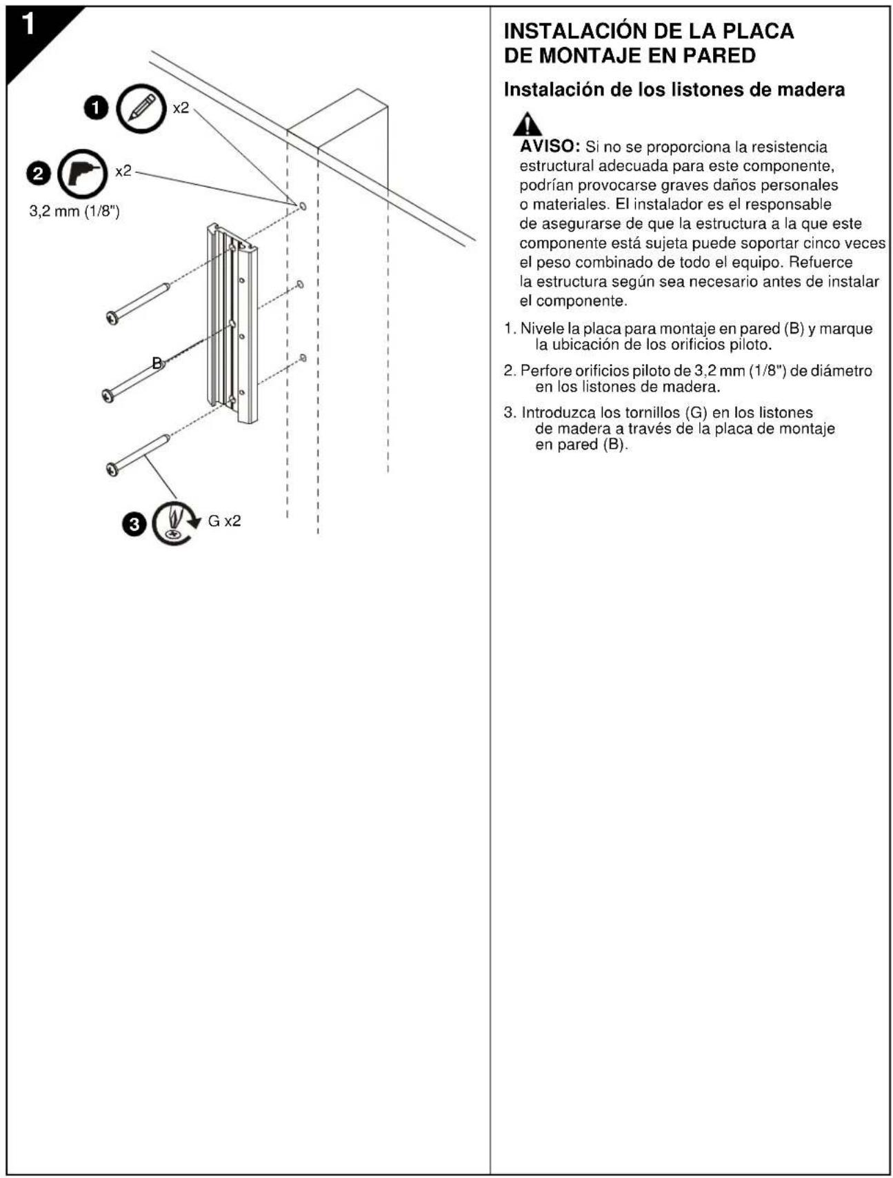
WARNING: Failure to provide adequate structural strength for this component can result in serious personal injury or damage to equipment! It is the installer's responsibility to make sure the structure to which this component is attached can support five times the combined weight of all equipment. Reinforce the structure as required before installing the component.

WARNING: Exceeding the weight capacity can result in serious personal injury or damage to equipment! It is the installer's responsibility to make sure the combined weight of all components attached to the iCSPTP2 does not exceed 40 lbs (18kg).

AVISOS Y PRECAUCIONES IMPORANTES!

Installation Instructions

PNEOCTEPEKHEHNE PNEOCTEPEKHEHNE npAodT B TOBMOCTB BAC K B30MxHOCTN NOPEKDEHH Hnna paspyuenoOBOPyDaaHNc. cnn Bu He cneyeer 3a COOTET CTAYouuMMNCHPTyPAAMN

PNEpyNPEKDEHnE.OTKa3HHTA,HTO60NoHOCTBO NOHRTbN CNEpOaBt 3a BCMA HNCHTpyKUMMA MOKET pNepcTc KcepebHOMy NteChOMy NopeKdEHHo NOpeKdEHmOcbpyOeHHoOBpOyDaeHHo-IMnOCbOeKdEHHO dbPAHHnRAPAHIN 3TO -OtaCTCBHeHOCTM OMTXAnHkY IOCTOBePTbI,TO 8C6 KOMIOHHTbI DIOIOHM Ibop30m COpaHs I YCTAHABMaI MOnrBaOHne PNEpOaTAEHNbIX HNCHTpyKu

PPEpyPNEXHNE.OTK36OeBcNMaTbApkBAtyH 0CpTyPKHyOgUdIaTTO 0KOMHOHEA MOKET PnBcEITK 0OpE3HOMY TELCHOMY NOBpEeDHeHNO KINIOBpeRtBa 0OcOpyOBHnE HTo -OTBCTBENHOCHTb MOHT AOKHnKa 0yDCOTepBcHr CPTKyPTy, K KOPOTR pNIOXHN 3OT 0KOMHOENT, MOKET NIODePckBtBA NTb PA3 O6bEhDnHHB 1Bec BOBO O6OpOBAHnN. YKpenETe cPTkyTpy KaTpeOyTER nepoMOKT AOKHnOMXHOHNT.

WARNING: Failure to provide adequate structural strength for this component can result in serious personal injury or damage to equipment! It is the installer's responsibility to make sure the structure to which this component is attached can support five times the combined weight of all equipment. Reinforce the structure as required before installing the component.
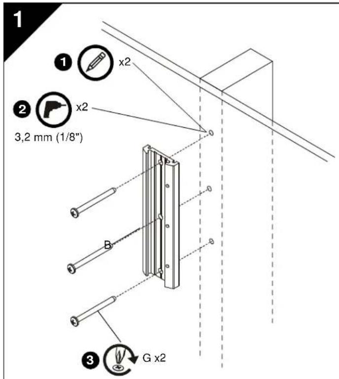
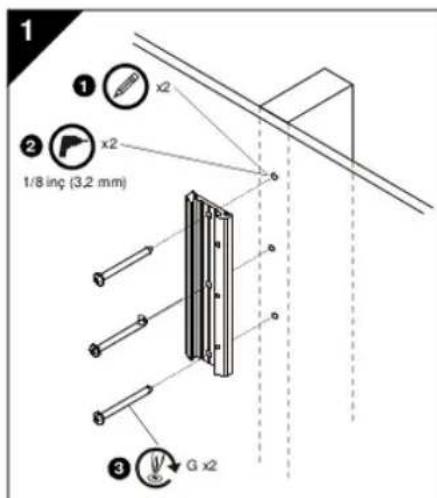
- Level wall plate (B) and mark locations of pilot holes.
- Drill 1 / 8'' (3.2mm) diameter pilot holes into wood stud.
- Install screws (G) through wall plate (B) into wood stud.
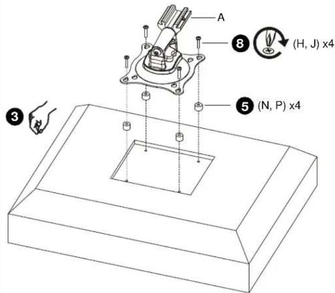
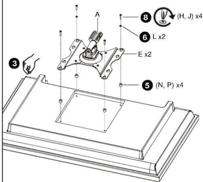
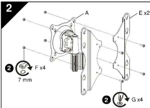
INSTALL HEAD ASSEMBLY TO DISPLAY

WARNING: Exceeding the weight capacity can result in serious personal injury or damage to equipment! It is the installer's responsibility to make sure the combined weight of all components attached to the iCSPTP2 does not exceed 40 lbs (18 kg).
- Proceed as follows:
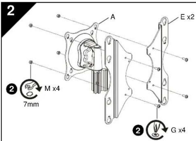
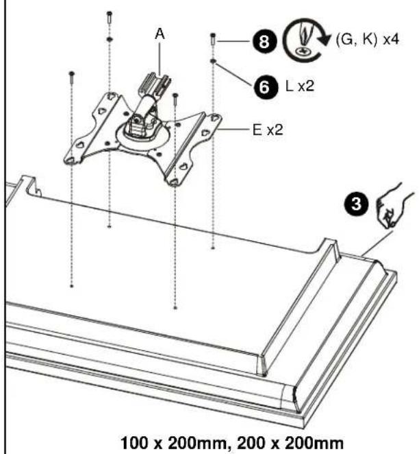
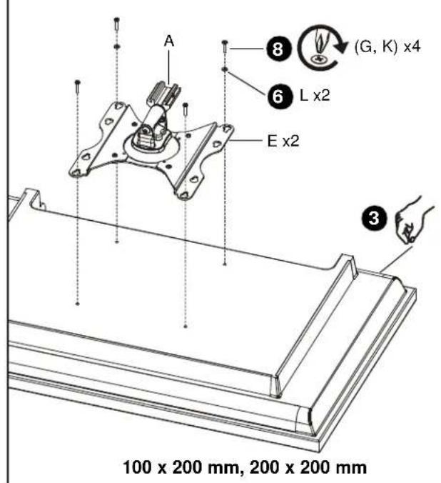
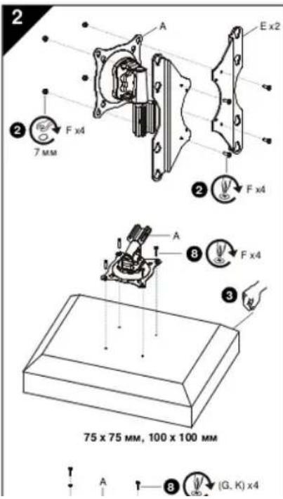
If display has a 100 × 200mm or 200 × 200mm mounting hole pattern, then proceed to Step 2 below and see figure at bottom left.
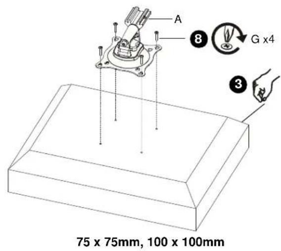
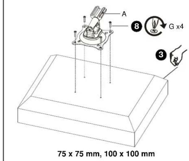
If display has a 75× 75mm or 100× 100mm mounting hole pattern, then proceed to Step 3 below. (See figure at middle left)
- Install screws (G) through brackets (E) and head assembly (A) into nuts (M). (See figure at top left)
-
Carefully place display face down on protective surface.
-
Proceed as follows:
If mounting holes are recessed into back surface of display, then proceed to Step 5 below.
If mounting holes are flush with back surface of display, then proceed to Step 6 below.
-
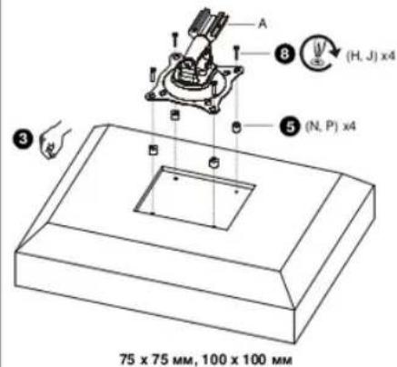
Place four spacers (N or P, as applicable) over each mounting hole on back of display. Select shortest spacer which will provide adequate fill. All spacers must be same length.
-
Select screw length:
-
For flush mounting holes use screws (G) or (K), as applicable.
If using spacers (N), then use screws (H).
If using spacers (P), then use screws (J). -
Orient head assembly (A) so that teardrop mounting holes are aligned with holes in display or holes in spacers (N, P), as applicable.
2
75× 75mm 100× 100mm
100 × 200mm, 200 × 200mm
INSTALL HEAD ASSEMBLY TO DISPLAY (Continued)

CAUTION: Using screws of improper size may damage your display! Proper screws will easily and completely thread into display mounting holes.
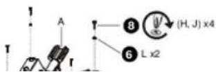
- Install selected screws through washers (L, if applicable), teardrop mounting holes, and spacers (N or P, if applicable) into display.
If installing 4mm diameter screws (G, H, or J) through brackets (E), then also use washers (L) for lower pair of teardrop mounting holes.
- Tighten all four screws. Do not overtighten!
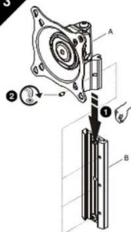
3
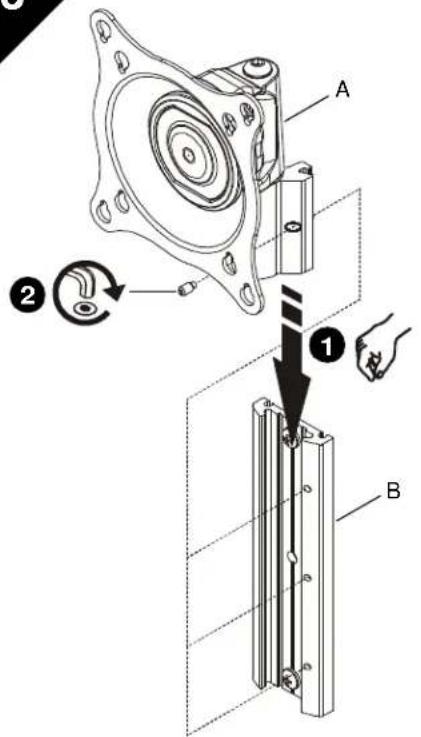
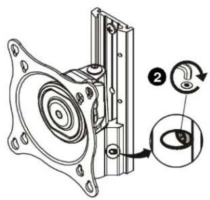
INSTALL HEAD ASSEMBLY TO WALL PLATE
- Align head assembly (A) with wall plate (B) and slide into position.
NOTE: Display not shown for clarity.

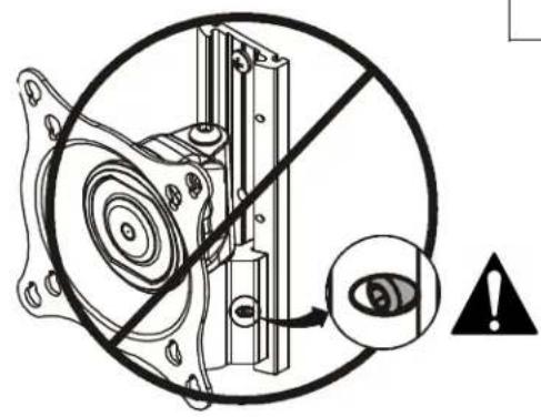
WARNING: Failure to align hex head screw with hole in wall plate (B) may allow head assembly (A) to fall, resulting in serious personal injury or damage to equipment! Hex head screw should fully recede into head assembly hole after tightening.
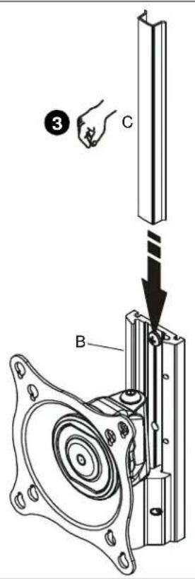
- Using hex key (R), tighten hex head screw in head assembly (A) ensuring that screw engages one of three holes in wall plate (B).
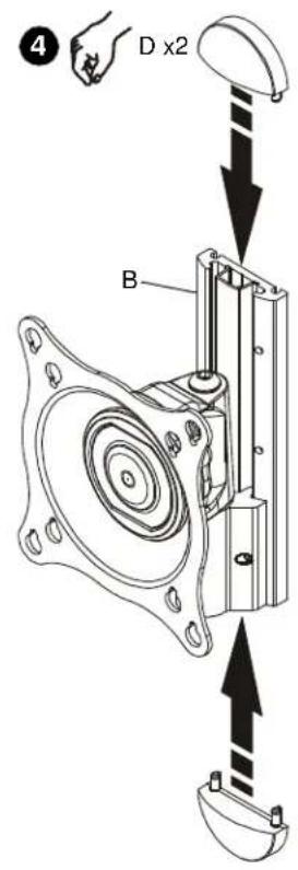
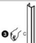
NOTE: Three holes are provided in wall plate (B) to provide height adjustment. - Align cover (C) with grooves in wall plate (B) and slide into position.
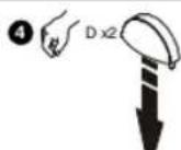
- Align caps (D) with holes in wall plate (B) and slide into position.
4
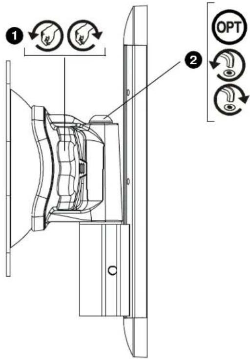
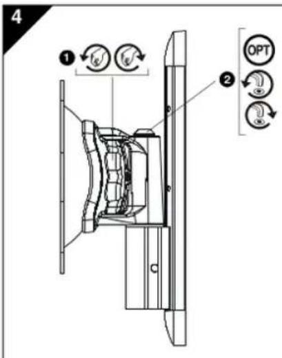
ADJUSTMENT

WARNING: Excessive loosening or tightening of adjustment mechanism can result in serious personal injury or damage to equipment!
- To adjust pitch/swivel/roll, slightly loosen adjustment knob (counterclockwise when looking at back of display), move display to desired angle, and retighten adjustment knob.
- OPTIONAL: Additional swivel adjustment may be made by slightly loosening or tightening adjustment screw using hex key (Q). Adjust screws ONLY as required to achieve desired tension.
KOPCONSTRUCTIE AAN WANDPLAAT BEVESTIGEN
KKOTOPO KPEMTCA DAHHB KOMTOHENT,MOITB
BbdepeKaTb HargyK, paHyo NtTKpaTHOMy Becy
BOBIOOBOPODABHIA.ECHNEOOXODMO.Nepe
yCTAHOBXOKOMNOHERTa yOHTB800 XOHCTpydmo
- Bapocnhtb hactehyo nactny (B) HOTMertntb
- PocBepnTB HanpaBnAoume OTeepCTm
DnAmeTpOM 3.2 MM (1/8) a depeBHHHcm Kapkace. - 3aephyu wypn (G) epees hacteHHy
KPEIIEHNE TONOBKN BCBOPE K DNCNIIEO

EYPNPEXKHEME: PnBbueuene DpycTmHOB
OEB HarykM NOeKET NOBHeCpeB3He TpBMeIM
EePENHEO BocpOaONHIIIIO, OcyueCTANHOoe
BOxOy, 063hAo npocNepHTs 3A TEM, YTO6b
MAHPAR MACCA BCEX KOMHOENTOB, yCTAOBNEHHx HA
PTP2, He npeBuaan18 kT (40fhytOB).
- Ioprodck peetb:
Ecrnnae nee maeet nae no Kpeekn 200x 200 mm 200 x 100mm,neepinx wary 2 danee no teky.
ECNDAHJINHEIMEHTAONHOKPENEXKHXBOTEPCTNApaemcPOM75X5MMM100X100MMnepeKTHxuay3dane noTecty.
- 3aBcHbYbMnTHb(G)hepe3ck6b(E)ircoN0ay b c6Oe(A)raRsin(B).
3.Axaypattho NONOKHTI DNZUNI INPUEBOTCPOHO BHA3 HaaaTHHYNOHOBXHOCT.
PIMMEYAHNE: POKAZAHs W66NOHx PENEXHOXO XTAEPTX 100 x 100 MM 200 x 200 MM; W66NOHx 75 x 75 MM x 100 x 200 MM AHAIOVWHL
- Nopapox dewctv:
EcnKKPENEXKHeOBePcTnAaLy6HbHbA3pHko noBepXHOCTbAcNnIe,nepeTnKwary5Hko ne TKeCTy.
EcnxpehNcHbteOBepTnpaonOnekHe 3anaDnue c3aHne nobepxochtuo dncnner. nepthKway5 Hnke No TeKry
- POMECTHTB HETMPE DNTAHAOHNHE BAYTNN (N IN N P B 3B3ACIMOCHT AOTYAAH) HAETMPE XEPHEMOX TBATECN HA 3ADNE CTEKHE PCTNNE. BILpTaC BAMAE KOKTKEI YATNY, DCCTAOHJME NO DNINHE. BOE ATYNK DIOKTHN6BtD ODN DNIHNA
2
KPEIIEHNEIIOBKNBCBOPE KINCIIIEO (npoJokHe)

QOCTEPKEHHE: PnncnnoB308Hm H enoepaenrpo aampea 0a3MooHO KOZENHe daNNner BHTNpu npabtnHoro O pAeNo nnoHocb taBnnaHbAcTcR a OHte OBePcTb DaCnE.
- 3aeeepyhtyaBbaophae BHeTbHepez3aia6b (L, ecnwnon7yto; Kanaenb4yke XpeneoHoe OTeBPTnN aDCTAHONHOte BynK (Nina P, ecnwnon7yto; aWcneN).
PnYcTaNBOeBnOaBNaEMPTOM4MM (G,H,NJB J C BoKOeE (T)AKoVcnBo308Ba7 bNBo(L)JrHnHeu NapbKanneBnBnKb WENEXHbXOTBePcTe. - 3aRhybBoeYtpeAHTHa.He nepetraea
3
KPEIIEHNE TONOBKNBCBOPE K HACTEHHOIIACTHNE
- Pnnooxntnooncoaekyacbope(A) X hacteHNOI nactine (B), bpoanrhty n andynnnhy HA mecto.
PIMMEAHHE:DMONNEIINHARNPHOCTHe nokasaH.

PENPYPKEKDEHNE: ECNI HOBCEMTBbNTC rnoaONnOD
mCTPAHNN KIOc hOePTEM BACTEHNO nactHE (B,yen
rnoaONA(A)MOETyNACTb,TO MOETNPwESEK CKepe3HN TpaAMM
nnnoepkDnHO o6pOyDANHn! BHTc rnoaONnOD noeCTPAHNN
KNK nooc zatarnanHn pOxNkBuNnNoHnO yonnnn
BOtEPCTVEyOnoNn.
- Knochom cseimrpanhnoi ronokn (R) 3aeepyntb binyt c rnonok noj weeimrpanhnoi knoy a yane ronok (A). Ta, rroobnht boen a oho texo otaeptvN hacteHNO nactte (B).
PIMMEUHAHE: H BACTHNOI PAACTINE (B) IMEOTOR TPR OTBERCTHDA perynlopoBix MBCOTAI. - Bctabnht kbpunck (C) kahanbnn Hn hacteHNOI nactine (B) n aenbHnht Hn mecto.
4.YCTAHOBHTbKoONHn(D)HAOTBpCTNHHACTEHHOINACTHEE(B)NCTABTHXHMACTO.
PERYUNPOBKA

PNEpyTPEJHEHc:Ype3eepHOO c0a5bneHnNk tATRtAeHnE pyrryTOPOHcEOHMOXMAHmMOKET NOHJIbCebp3HHe TPOBMMIbNOBpeKbENDE 6oBCyDQAnHHI
1.IINIpyENIOBKNHANOHOAPENTAAHNOBOPATAKHPA HEMBOHOOCNABTpyENIOPOBONHYPYOKTY(PONYHBCCOBCTPNK,ECMCMOTPBnHA3ADHOCTEHKYDANTyCHTANYCYTAHOIBN DYMOHNPOYKRY
2. HEO6R3ATEbHO:MOKOponHHTENHO peryTNbBONoPOT, cIeNkOcJIaBnKIN 3aTITIRNA BPERYNOBCHY BNHT KTHOKOM C wEETPAHNOI TOKAOB (Q, PeryTNPOBaT bHNTO TIOKBO HACTONHO, HAKCtBO ITO HEOXoDMIO PAONYYNEHNG HYHXOTARKHEMIA
MONTOWANIE ZESPOLU GLOWICY DO PLYTY SCINNEJ
TPOEIAONOH:YypeBkoIgIeBouaIgIbIgUauuouuouuauuauuuuauuauuuuuuuuuuuuuuuuuuuuuuuuuuuuuuuuuuuuuuuuuuuuuuuuuuuuuuuuuuuuuuuuuuuuuuuuuuuuuuuuuuuuuuuuuuuuuuuuuuuuuuuuuuuuuuuuuuuuuuuuuuuuuuuuuuuuuuuuuuuuuuuuuuuuuuuuuuuuuuuuuuuuuuuuuuuuuuuUU
- Iia puiian ta yuivai kaiang trepatpogc/ kuiany, Eepaote aagpo to kuiou puiyuan (apoeoepoqpo 0rto BAETETE OTO mow poc tnc obov), metokwate trny oovn atyn etiun) vuaia kaiavao To koumi pueyanc
- IPOAPETKIO: Emltloovpuaon mnc npaoqng paoi va emtuybci e aagpu bcbiaa n ibuwa miboc poaunx npoipouvivac enaywko kai (O). Pubyote n bis BMO Omc amaritir va my tceumn in cimthountoons.
DUVAR PLAKASINI DUVARAMONTE ETME
Ahsap Citaya Montaj
MANUFACTURERS DECLARATION OF CONFORMITY
For
Product identification:
Model/type : iCSPTP2
Category (description) : Mounting devices, Stands and other Accessories, to be used with entertainment electronics
Brand : iC
Manufacturer: CSAV Inc. 8401 Eagle Creek Parkway Savage, MN 55378
EU Representative:
CSAV Inc.
Fellennoord 130 5611
ZB Einhoven
The Netherlands
31(0)402668620
| Concerning | ||||
| EMC | Safety | |||
| A sample of the product has been tested by: | Not Applicable | CSAV Inc. | ||
| Test report reference | . | |||
| Applied standards | EN 60065 :2002 | |||
Means of conformity
We declare under our sole responsibility that this product is in conformity with Directive 93/68/EEC (Marking), 98/37/EC (Machinery) 2001/95/EC (Safety) and/or complies to the essential requirements and all other relevant provisions of the based on test results using (non)harmonized standards in accordance with the Directives mentioned

Manufactured by CHIEF®
iC Mounting Solutions
USA·8401 Eagle Creek Parkway, Suite 700·Savage, Minnesota 55378·800.572.1373
Europe/Middle East/Africa ^+ 31 (0)40 2668620
www.icmounts.com