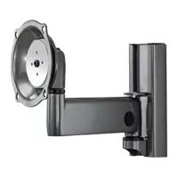
iCMPSA4T02 - Flat screen mount Chief - Free user manual and instructions
Find the device manual for free iCMPSA4T02 Chief in PDF.


| Product Type | Flat Panel Wall Mount |
| Brand | Chief |
| Model | iCMPSA4T02 |
| Maximum Load Capacity | 34 kg (75 lb) |
| VESA Compatibility | 100x100, 200x100, 200x200, 300x300, 400x200, 400x400 mm |
| Material | Steel |
| Functions | Adjustable tilt, swivel, extension |
| Cable Management | Integrated with removable cover |
| Wall Mount Type | On wood stud or concrete (anchors included) |
| Max Drywall Thickness | 15.9 mm |
| Tension Adjustment | Adjustable pitch, extension, and swivel via tension screws |
| Mount Weight | Approximately 5 kg (estimated) |
| Dimensions (W x H x D) | Approximately 50 x 25 x 10 cm (arm folded, estimated) |
| Maintenance | Clean with a soft, dry cloth |
| Safety | Do not exceed load capacity; check wall strength |
| Supplied Parts | Base plate, pivoting arm, mounting brackets, screws, anchors, tools |
| Required Tools | 14.2 mm socket wrench, Phillips screwdriver, hex keys provided |
| Installation on Wood Stud | Drill 6.3 mm, lag bolts with washers |
| Installation on Concrete | Drill 10 mm, anchors, lag bolts with washers |
Frequently Asked Questions - iCMPSA4T02 Chief
User questions about iCMPSA4T02 Chief
0 question about this device. Answer the ones you know or ask your own.
Ask a new question about this device
Download the instructions for your Flat screen mount in PDF format for free! Find your manual iCMPSA4T02 - Chief and take your electronic device back in hand. On this page are published all the documents necessary for the use of your device. iCMPSA4T02 by Chief.
USER MANUAL iCMPSA4T02 Chief
DISCLAIMER
Milestone AV Technologies, and its affiliated corporations and subsidiaries (collectively, "Milestone"), intend to make this manual accurate and complete. However, Milestone makes no claim that the information contained herein covers all details, conditions or variations, nor does it provide for every possible contingency in connection with the installation or use of this product. The information contained in this document is subject to change without notice or obligation of any kind. Milestone makes no representation of warranty, expressed or implied, regarding the information contained herein. Milestone assumes no responsibility for accuracy, completeness or sufficiency of the information contained in this document.
Chief® and Centris™ are trademarks of Milestone AV Technologies. All rights reserved.

IMPORTANT WARNINGS AND CAUTIONS!
WARNING: A WARNING alerts you to the possibility of serious injury or death if you do not follow the instructions.

CAUTION: A CAUTION alerts you to the possibility of damage or destruction of equipment if you do not follow the corresponding instructions.

WARNING: Failure to read, thoroughly understand, and follow all instructions can result in serious personal injury, damage to equipment, or voiding of factory warranty! It is the installer's responsibility to make sure all components are properly assembled and installed using the instructions provided.

WARNING: Failure to provide adequate structural strength for this component can result in serious personal injury or damage to equipment! It is the installer's responsibility to make sure the structure to which this component is attached can support five times the combined weight of all equipment. Reinforce the structure as required before installing the component. The wall to which the mount is being attached may have a maximum drywall thickness of 5/8" (15.9mm).

WARNING: Exceeding the weight capacity can result in serious personal injury or damage to equipment! It is the installer's responsibility to make sure the combined weight of all components attached to the iCMPSA4 does not exceed 75 lbs (34kg). Use with products heavier than the maximum weight indicated may result in collapse of the mount and its accessories causing possible injury.

PARTS
![A (1) [single arm mount] C (1) [center bracket] B (1) [wall plate] D (1) [cover] F (2) [anchor] G (2) 3/8" x 2-1/2" H (2) 3/8" E (2) [vertical bracket] J (2) 8-32 x 3/8" K (1) 3/16" L (1) 7/32" M (4) M4 x 8mm N (10) M4 x 12mm P (6) M4 x 25mm Q (6) M5 x 12mm R (6) M5 x 25mm S (6) M5 x 30mm T (6) M5 x…](/content/2026/02/354602/images/de5036f1228fb49415df385543d5a5021eb08be25b800480bc4324879311fc75.jpg)
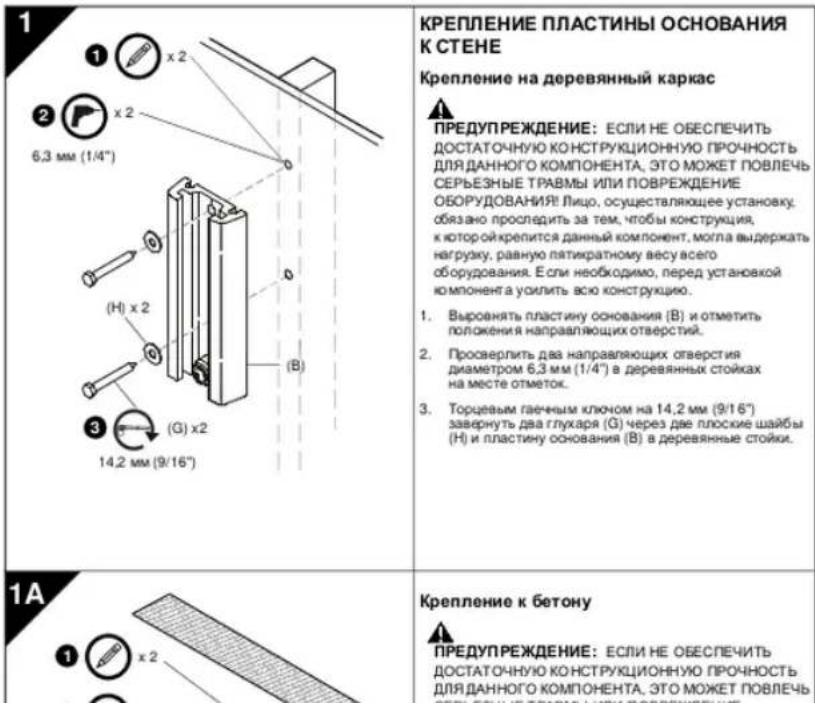
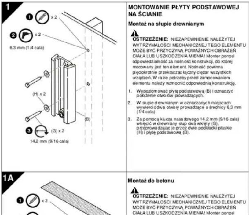
1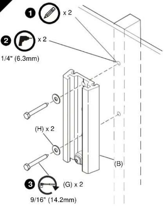 | INSTALL BASE PLATE TO WALLWood Stud InstallationWARNING: FAILURE TO PROVIDE ADEQUATE STRUCTURAL STRENGTH FOR THIS COMPONENT CAN RESULT IN SERIOUS PERSONAL INJURY OR DAMAGE TO EQUIPMENT! It is the installer's responsibility to make sure the structure to which this component is attached can support five times the combined weight of all equipment. Reinforce the structure as required before installing the component.Level base plate (B) and mark locations of pilot holes.Drill two 1/4" (6.3mm) diameter pilot holes into wood studs at marks.Using 9/16" (14.2mm) socket wrench, install two lag screws (G) through two flat washers (H) and base plate (B) into wood studs. |
1A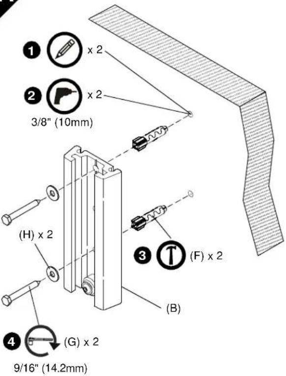 | Concrete InstallationWARNING: FAILURE TO PROVIDE ADEQUATE STRUCTURAL STRENGTH FOR THIS COMPONENT CAN RESULT IN SERIOUS PERSONAL INJURY OR DAMAGE TO EQUIPMENT! It is the installer's responsibility to make sure the structure to which this component is attached can support five times the combined weight of all equipment. Reinforce the structure as required before installing the component.Level base plate (B) and mark locations of pilot holes.Drill two 3/8" (10mm) diameter pilot holes into mounting surface.Install two anchors (F) into pilot holes.Using 9/16" (14.2mm) socket wrench, install two screws (G) through two flat washers (H) and wall plate (B) into two anchors (F).CAUTION: Do NOT overtighten screws! |
2
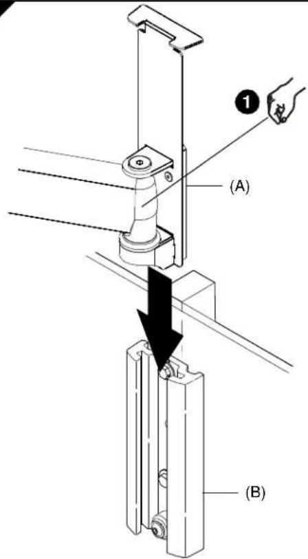
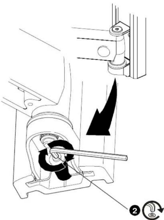
INSTALL SWING ARM TO BASE PLATE
IMPORTANT! If the display has a 100 x 100mm recessed mounting hole pattern, then display must be mounted to swing arm (A) before swing arm is installed to base plate (B). See "INSTALL DISPLAY, 100 x 100mm Recessed Mounting Hole Pattern". Continue below after display is installed.

CAUTION: PERSONAL INJURY MAY OCCUR IF SWING ARM COLLAPSES AGAINST FINGERS! Be alert, keeping hands and fingers out of pinch points during installation.
- Slide swing arm mounting bracket (A) down into base plate (B).
- Secure swing arm (A) to base plate (B) by tightening screw with hex key (K).
3
INSTALL DISPLAY
IMPORTANT! Proceed as directed below:
- If installing a display with a 200x100, 200x200, 300x300, 400x200, or 400x400mm mounting hole pattern, proceed to Step 3A.
• If installing a display with a 100x100mm mounting hole pattern, proceed to step 3B or 3C, as applicable.
3A
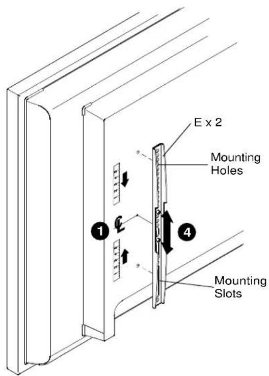
200x100, 200x200, 300x300, 400x200 or 400x400 Mounting Hole Pattern
Attaching Vertical Brackets

WARNING: IMPROPER INSTALLATION CAN LEAD TO MOUNT FALLING CAUSING SERIOUS PERSONAL INJURY OR DAMAGE TO EQUIPMENT! DO NOT substitute hardware. Only use hardware provided or specified by manufacturer.
- Determine and mark the vertical center position between the left side upper and lower mounting holes in display.
- Determine and mark the vertical center position between the right side upper and lower mounting holes in display.
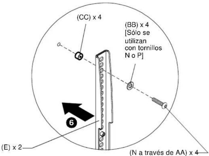
- Orient vertical mounting bracket (E) so that mounting holes are on top and mounting slots are on bottom.
- Align mounting holes and slots in vertical mounting bracket (E) with upper and lower mounting holes in display.
- Adjust vertical mounting bracket (E) position until mark made in Step 1 aligns with center mark in vertical mounting bracket (E).
- Secure left side vertical mounting bracket (E) to display using two Phillips pan head screws (N through AA).
NOTE: Also use #10 flat washers (BB) if using screws N or P.
NOTE: If the display has a recessed mounting surface, protrusions or a power box, a spacer and longer mounting hardware must be placed between the display and vertical mounting brackets (E).
- Repeat Steps 3 through 6 for right side vertical mounting bracket using the same hole locations to align brackets horizontally.
![3A (CC) x 4 (BB) x 4 [Only used with screws N or P] (E) x 2 (N through AA) x 4](/content/2026/02/354602/images/d309e78abca0104d2f8fa586e86a7136b88cc5fa1efac1b3e04a8a91644b7515.jpg)
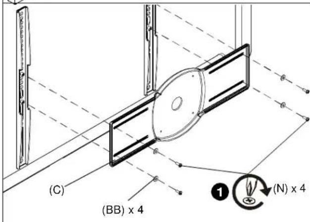
Attaching Center Bracket
- Attach center bracket (C) to vertical mounting brackets (E) using four M4 x 12mm Phillips head screws (N) and four #10 flat washers (BB).
- Attach iCMPSA4 to bracket using two M4 x 8mm Phillips head cap screws (M) in the upper two mounting holes.
- Complete attachment of iCMPSA4 using two M4 x 8mm Phillips head cap screws (M) in the lower two mounting holes.
- Proceed to Step 3B.
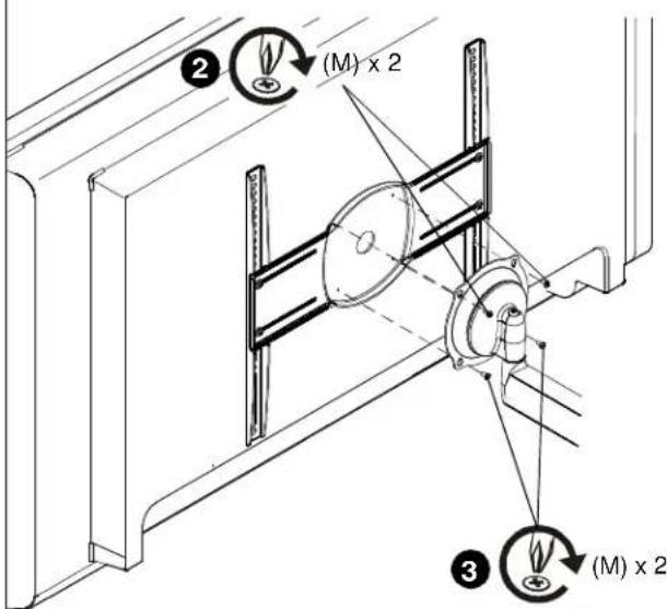
3B
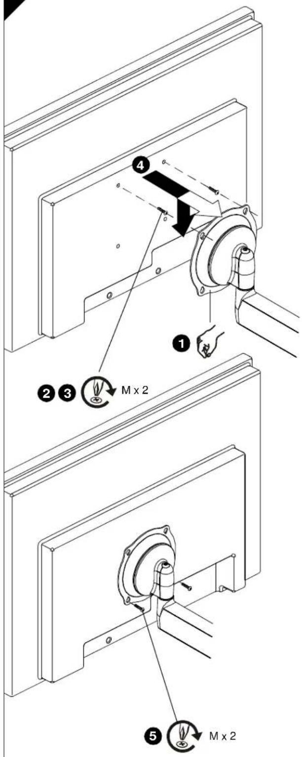
100 x 100mm Flush Mounting Hole Pattern
IMPORTANT! This procedure only applicable when 100x100mm mounting holes on back of display are flush with back surface of display, OR brackets (C, E) were previously installed per Step 3A.

WARNING: EXCEEDING THE WEIGHT CAPACITY CAN RESULT IN SERIOUS PERSONAL INJURY OR DAMAGE TO EQUIPMENT! It is the installer's responsibility to make sure the combined weight of all components attached to the iCMPSA4 does not exceed 75 lbs (34 kg).
- Ensure Centris bracket can swivel and tilt easily, yet still be tight enough to hold display in desired position. Adjust as required before proceeding. See "ADJUSTMENT".

CAUTION: USING SCREWS OF IMPROPER SIZE CAN DAMAGE DISPLAY! Screws should easily and completely thread into display mounting holes.
-
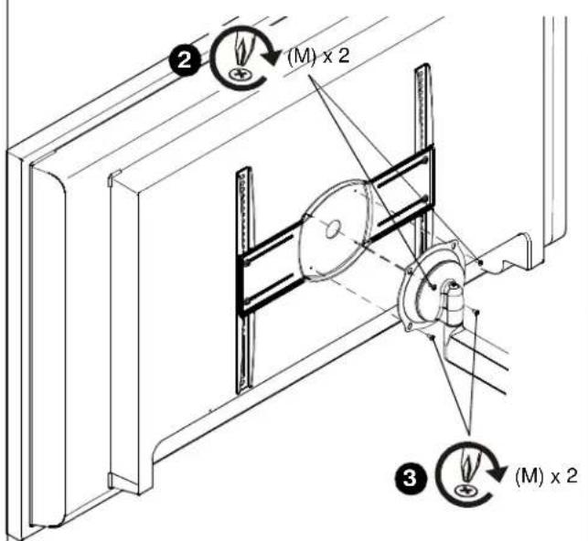
Using a Phillips screwdriver, install two screws (M) into upper threaded mounting holes in back of display (or in brackets C, E; if installed).
-
Thread screws completely into display (or in brackets C, E; if installed), then back out 3 complete turns.

WARNING: INADEQUATE THREAD ENGAGEMENT IN DISPLAY CAN LEAD TO MOUNT FALLING CAUSING SERIOUS PERSONAL INJURY OR DAMAGE TO EQUIPMENT! Back out screws ONLY as necessary to allow installation of Centris bracket!
- Lift and align display so that screws in back of display (or in brackets C, E; if installed) fit into upper teardrop mounting holes in Centris bracket. Lower display into place.
NOTE: DO NOT tighten screws at this time.
-
Using Phillips screwdriver, install two screws (M) through lower teardrop mounting holes in Centris bracket into display (or in brackets C, E; if installed).
-
Tighten all four screws (M). Do not overtighten!
3C
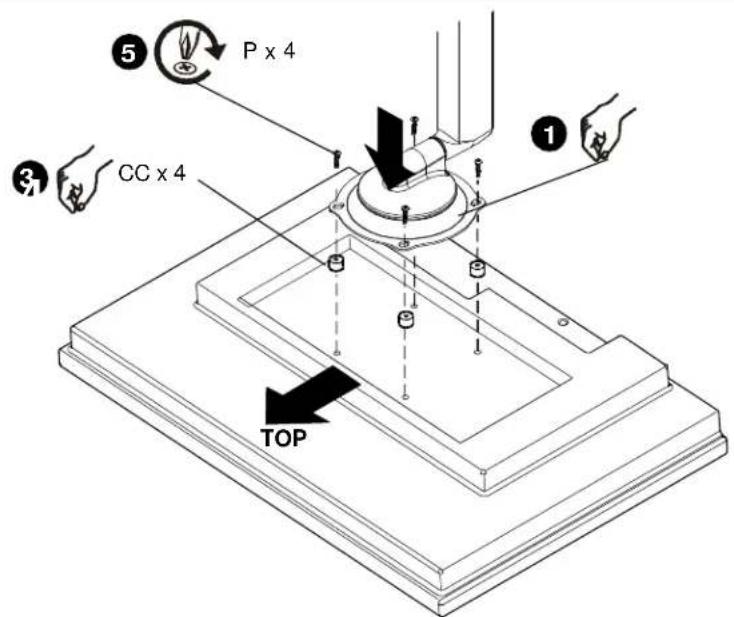
100 x 100mm Recessed Mounting Hole Pattern
IMPORTANT! This procedure only applicable when 100x100mm mounting holes on back of display are recessed into back surface of display.

WARNING: EXCEEDING THE WEIGHT CAPACITY CAN RESULT IN SERIOUS PERSONAL INJURY OR DAMAGE TO EQUIPMENT! It is the installer's responsibility to make sure the combined weight of all components attached to the iCMPSA4 does not exceed 75 lbs (34 kg).
- Ensure Centris bracket can swivel and tilt easily, yet still be tight enough to hold display in desired position. Adjust as required before proceeding. See "ADJUSTMENT."
- Carefully place display face down on protective surface.

CAUTION: USING SCREWS OF IMPROPER SIZE CAN DAMAGE DISPLAY! Screws should easily and completely thread into display mounting holes.
- Place four spacers (CC) over mounting holes in display back.
- Orient mount so that teardrop mounting holes in Centris bracket are aligned with holes in four spacers (CC).

WARNING: INADEQUATE THREAD ENGAGEMENT IN DISPLAY CAN LEAD TO MOUNT FALLING CAUSING SERIOUS PERSONAL INJURY OR DAMAGE TO EQUIPMENT!
- Using a Phillips screwdriver, install four screws (P) through four teardrop mounting holes in Centris bracket and spacers (CC) into display. Tighten all four screws (P). Do not overtighten!
- Continue with "INSTALL SWING ARM TO BASE PLATE".
4
ADJUSTMENT
- To adjust pitch tension, slightly loosen or tighten adjustment screw as required using hex key (K).
NOTE: If display is mounted to swing arm (A) then first disconnect all cables and remove display (Refer to "INSTALL DISPLAY"). - To adjust extension and swivel tension, slightly loosen or tighten adjustment screws as required using hex keys (K, L).

5
CABLE MANAGEMENT

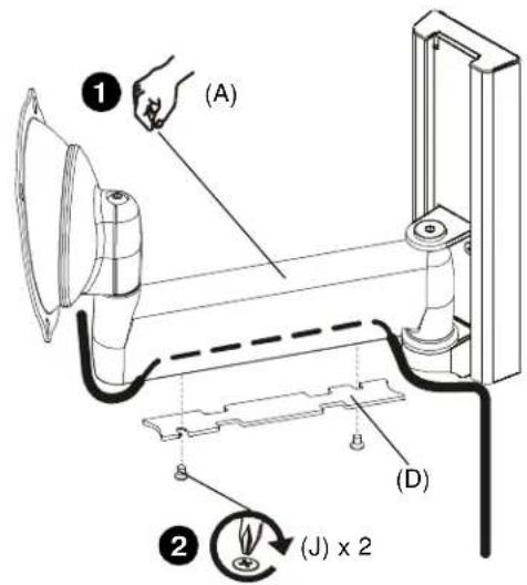
CAUTION: Ensure that adequate cable slack exists for movement of display, and that cables will not be pinched by installation of cover (D) or screws (J).
- Carefully insert cables into cavity located in lower portion of arm assembly (A).
- Install cover (D) with two screws (J).
Unir soporte central
Modelo de orifícios de montagem à superfície de 100 x 100 mm
INSTALLAZIONE DEL BRACCIO BASCULANTE SULLA PIASTRA DI BASE
ZWENKARM AAN BASISPLAAT BEVESTIGEN
WAARSCHUWING: ONEIGENLIJKE
Bevestig de middelste beugel
INSTALLER LE BRAS PIVOTANT SUR LA PLAQUE DE BASE
MONTERING AF SVINGARM PÅ BUNDPLADE
100 x 100 mm plant monteringshulmønster
MONTERA SVÄNGARMEN PÅ BASPLATTAN
Montera mittfästet
KÄÄNTÖVARREN ASENTAMINEN ALUSLAATTAAN
MONTOWANIE RAMIENIA RUCHOMEGO DO PŁYTY PODSTAWOWEJ
HAREKETLİ KOLU TABAN PLAKASINA MONTE ETME
A LENGÖKAR FELSZERELÉSE AZ ALAPLEMEZRE
©2009 Milestone AV Technologies. The iC Logo and StowAway are trademarks of Chief Manufacturing, a products division of Milestone AV Technologies, a Duchossois Group Company. All rights reserved
Patents and patents pending. Milestone AV Technologies, Savage, MN 55378, USA
11/09
8800-002042 Rev 00

- DISCLAIMER
- IMPORTANT WARNINGS AND CAUTIONS
- INSTALL SWING ARM TO BASE PLATE
- 3
- INSTALL DISPLAY
- 3A
- 200X100, 200X200, 300X300, 400X200 OR 400X400 MOUNTING HOLE PATTERN
- ATTACHING VERTICAL BRACKETS
- ATTACHING CENTER BRACKET
- 3B
- 100 X 100MM FLUSH MOUNTING HOLE PATTERN
- 3C
- 100 X 100MM RECESSED MOUNTING HOLE PATTERN
- 4
- ADJUSTMENT
- 5
- CABLE MANAGEMENT
- UNIR SOPORTE CENTRAL
- MODELO DE ORIFÍCIOS DE MONTAGEM À SUPERFÍCIE DE 100 X 100 MM
- INSTALLAZIONE DEL BRACCIO BASCULANTE SULLA PIASTRA DI BASE
- ZWENKARM AAN BASISPLAAT BEVESTIGEN
- BEVESTIG DE MIDDELSTE BEUGEL
- INSTALLER LE BRAS PIVOTANT SUR LA PLAQUE DE BASE
- MONTERING AF SVINGARM PÅ BUNDPLADE
- 100 X 100 MM PLANT MONTERINGSHULMØNSTER
- MONTERA SVÄNGARMEN PÅ BASPLATTAN
- MONTERA MITTFÄSTET
- KÄÄNTÖVARREN ASENTAMINEN ALUSLAATTAAN
- MONTOWANIE RAMIENIA RUCHOMEGO DO PŁYTY PODSTAWOWEJ
- HAREKETLİ KOLU TABAN PLAKASINA MONTE ETME
- A LENGÖKAR FELSZERELÉSE AZ ALAPLEMEZRE
Brand : Chief
Model : iCMPSA4T02
Category : Flat screen mount