
ARYAL S2 E DUAL - TRIAL - Air conditioner outdoor unit OLIMPIA SPLENDID - Free user manual and instructions
Find the device manual for free ARYAL S2 E DUAL - TRIAL OLIMPIA SPLENDID in PDF.
| Product type | Air conditioner outdoor unit |
| Brand | OLIMPIA SPLENDID |
| Model | ARYAL S2 E DUAL - TRIAL |
| Refrigerant | R32 (Flammable A2L) |
| Power supply | 220-240 V ~ 50 Hz |
| Protection fuse | T20A/250VAC (units <24000 Btu/h) or T30A/250VAC |
| Operating modes | Cool, Heat, Dry, Fan only |
| Ambient temperature range (Cool) | 17°C to 32°C |
| Outdoor temperature range (Cool) | 0°C to 50°C |
| Ambient temperature range (Heat) | 0°C to 30°C |
| Outdoor temperature range (Heat) | -15°C to 24°C |
| Compressor protection | 3-minute restart delay |
| Max. pipe length (Dual) | 40 m |
| Max. pipe length (Trial) | 60 m |
| Max. height between indoor and outdoor units | 15 m |
| Minimum room area | Variable depending on refrigerant quantity (see manual) |
| Air filter maintenance | Every 2 weeks |
| Included accessories | Manual, installation plate, screws, drainage gasket, connectors |
| Auto restart after power outage | Yes |
| Installation type | Wall-mounted |
Frequently Asked Questions - ARYAL S2 E DUAL - TRIAL OLIMPIA SPLENDID
User questions about ARYAL S2 E DUAL - TRIAL OLIMPIA SPLENDID
0 question about this device. Answer the ones you know or ask your own.
Ask a new question about this device
Download the instructions for your Air conditioner outdoor unit in PDF format for free! Find your manual ARYAL S2 E DUAL - TRIAL - OLIMPIA SPLENDID and take your electronic device back in hand. On this page are published all the documents necessary for the use of your device. ARYAL S2 E DUAL - TRIAL by OLIMPIA SPLENDID.
USER MANUAL ARYAL S2 E DUAL - TRIAL OLIMPIA SPLENDID
natural_image
Line drawing of a multi-chamber HVAC air conditioner unit with visible fan blades and mounting brackets (no text or symbols)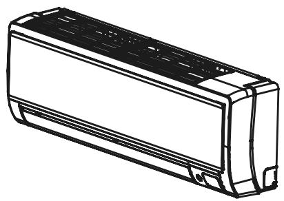
natural_image
Line drawing of a rectangular air conditioner unit (no text or symbols)natural_image
Line drawing of a multi-compartment air conditioner unit with fan blades (no text or symbols)natural_image
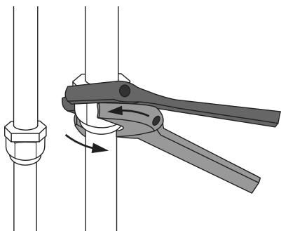
Diagram of a mechanical clamp or tool operating on a pipe fitting (no text or symbols present)• Collegare i tubi refrigeranti
- Collegare i fili
natural_image
Line drawing of a pressure gauge and two gauges with a hook, mounted on a base with no text or symbolsnatural_image
Line drawing of a handheld electronic device with a coiled cable and bulb (no text or symbols)
natural_image
Technical line drawing of a front-end air conditioner unit with fan and side-mounted buttons (no text or symbols)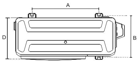
natural_image
Technical illustration of two mechanical clamping devices with no visible text or symbols

x
DUAL

flowchart
graph TD
    subgraph Inputs
        S1["S(1)"] --> OZIONALE["OPZIONALE"]
        S2["S(2)"] --> OZIONALE
        S3["S(A)"] --> OZIONALE
        S4["N(A)"] --> OZIONALE
        S5["N(A)"] --> OZIONALE
        S6["L(A)"] --> OZIONALE
        S7["L(A)"] --> OZIONALE
    end
    OZIONALE --> TOB["TO B"]
    OZIONALE --> TOA["TO A"]
    OZIONALE --> ALIMENTAZIONE["Alimentazione elettrica"]
    OZIONALE --> TOB
    OZIONALE --> TOA
    style OZIONALE fill:#f9f,stroke:#333
    style TOB fill:#ccf,stroke:#333
    style TOA fill:#cfc,stroke:#333
flowchart
graph TD
    subgraph OPZIONALE
        A1["LN S④"] --> TOB["TO B"]
        A2["ALIMENTAZIONE elettrica"] --> TOA["TO A"]
    end
    subgraph LN S
        B1["LN S④"] --> TOA
    end
    S1["S(1)"] --> TOB
    S2["S(2)"] --> TOB
    S3["S(A)"] --> TOB
    S4["N(A)"] --> TOB
    S5["L(A)"] --> TOB
    S6["N(B)"] --> TOB
    S7["L(B)"] --> TOB
    S8["L"] --> TOB
    TOB --> L["To B"]
    TOB --> N["To A"]
三
flowchart
graph TD
    subgraph Power
        A["Power Supply"] --> B["Optional Unit 1"]
        A --> C["Optional Unit 2"]
        D["Optional Unit 3"] --> E["Optional Unit 4"]
    end

    subgraph To Indoor Unit A
        F["To indoor unit A"] --> G["Optional Unit 5"]
        H["To indoor unit B"] --> I["Optional Unit 6"]
    end

    subgraph To Indoor Unit B
        J["To indoor unit B"] --> K["Optional Unit 7"]
        L["To indoor unit C"] --> M["Optional Unit 8"]
    end

    subgraph To Indoor Unit C
        N["To indoor unit C"] --> O["Optional Unit 9"]
    end

    style Power fill:#f9f,stroke:#333
    style To Indoor Unit A fill:#ccf,stroke:#333
    style To Indoor Unit B fill:#ccf,stroke:#333
    style To Indoor Unit C fill:#ccf,stroke:#333
①
↓
①

1 - GENERAL WARNINGS....2
1.1 - NOTES REGARDING FLUORINATED GASES 4
1.2 - Proper use 6
1.3 - Hazardous zones 6
1.4 - FUSE SPECIFICATIONS....6
2 - INSTRUCTIONS FOR INSTALLATION....7
3 - APPLIANCE DESCRIPTION ....7
3.1 - WALL INSTALLATION....7
3.2 - MINIMUM AMBIENT AREA IN THE CASE OF REFRIGERANT GAS LOADING....8
3.3 - OPERATING TEMPERATURE....8
3.4 - RECOMMENDATIONS FOR ENERGY SAVINGS....9
4 - OPERATIONS AND MAINTENANCE ......9
5 - TROUBLESHOOTING....10
5.1 - SAFETY PRECAUTIONS....10
5.2 - COMMON ISSUES 10
5.3 - FUNCTIONAL ASPECTS NOT TO BE MISTAKEN FOR ANOMALIES 11
6 - ACCESSORIES 12
7 - INSTALLATION ...... 13
7.1 - PROCEDURES FOR INSTALLATION 13
7.2 - INSTALLATION DIAGRAM....14
7.2.1 - Specifications 15
7.3 - OUTDOOR UNIT INSTALLATION....16
7.3.1 - Step 1: Select installation location....16
7.3.2 - Special considerations for extreme weather 16
7.3.3 - Step 2: Install drain joint (Heat pump unit only)....16
7.3.4 - Step 3: Anchor outdoor unit....17
7.4 - UNIT MOUNTING DIMENSIONS....17
7.5 - NOTES ON DRILLING HOLE IN WALL 18
7.6 - REFRIGERANT PIPING CONNECTION 18
7.6.1 - Step 1: Cut pipes....18
7.6.2 - Step 2: Remove burrs ..... 19
7.6.3 - Step 3: Flare pipe ends ..... 19
7.6.4 - Step 4: Connect pipes....20
8 - WIRING....21
8.1 - EXTERNAL UNIT WIRING 22
9 - AIR EVACUATION....23
9.1 - INSTALLATION DIAGRAM....25
9.2 - TEST RUN....25
10 - FUNCTION OF AUTOMATIC WIRING/PIPING CORRECTION 26

DISPOSAL
This symbol on the product or its packaging indicates that the appliance cannot be treated as normal domestic trash, but must be handed in at a collection point for recycling electric and electronic appliances. Your contribution to the correct disposal of this product protects the environment and the health of your fellow men. Health and the environment are endangered by incorrect disposal.
Further information about the recycling of this product can be obtained from your local town hall, your refuse collection service, or in the store at which you bought the product.
This regulation is valid only in EU member states.
0 - SYMBOLS
The pictograms in the next chapter provide the necessary information for correct, safe use of the machine in a rapid, unmistakable way.

Index
Paragraphs marked with this symbol contain very important information and recommendations, particularly as regards safety. Failure to comply with them may result in:
- danger of injury to the operators
- loss of the warranty
- refusal of liability by the manufacturer.

HAZARD
Indicates that the appliance uses inflammable refrigerant. If the refrigerant escapes and is exposed to a source of external ignition, there is a fire risk.

Signals to the personnel that the operation described could cause electrocution if not performed according to the safety rules.

GENERIC DANGER
It informs the personnel concerned that if the operation is not carried out in compliance with the safety regulations, it presents the risk of suffering physical damage.
1 - GENERAL WARNINGS
WHEN USING ELECTRICAL EQUIPMENT, BASIC SAFETY PRECAUTIONS MUST ALWAYS BE FOLLOWED IN ORDER TO REDUCE RISKS OF FIRE, ELECTRIC SHOCKS AND INJURY, INCLUDING THE FOLLOWING:

- This document is restricted in use to the terms of the law and may not be copied or transferred to third parties without the express authorization of the manufacturer, OLIMPIA SPLENDID.
Our machines are subject to change and some parts may appear different from the ones shown here, without this affecting the text of the manual in any way. - Read this manual carefully before performing any operation (installation, maintenance, use) and follow the instructions contained in each chapter.
- Make all personnel involved in transport and installation of the machine aware of these instructions.
- THE MANUFACTURER IS NOT RESPONSIBLE FOR DAMAGES TO PERSONS OR PROPERTY CAUSED BY FAILURE TO FOLLOW THE INSTRUCTIONS IN THIS MANUAL.
- The manufacturer reserves the right to make any changes it deems advisable to its models, although the essential features described in this manual remain the same.
- The installation and maintenance of air-conditioners like this one may be hazardous as they contain a cooling gas under pressure as well as powered parts.
Therefore, the installation, first startup and subsequent maintenance should be carried out exclusively by authorized, qualified personnel.
- Failing to comply with the instructions contained in this manual, and using the unit with temperatures exceeding the permissible temperature range will invalidate the warranty.
- Routine maintenance of the filters and general external cleaning can be done by the user as these operations are not difficult or dangerous.
- During installation and maintenance, respect the precautions indicated in the manual, and on the labels applied inside the units, as well as all the precautions suggested by good sense and by the safety regulations in effect in your country.


- Perform installation and maintenance using equipment that is suitable for inflammable gas.

- Always wear gloves and protective goggles when performing any operations on the refrigerating side of the units.
EN - 2


- Air conditioners must not be installed in places containing inflammable gasses, explosive gasses, or in very humid environments (laundries, greenhouses, etc.), or in places where there are machines that generate very great heat.
-
In case of replacement of parts, use only original OLIMPIA SPLENDID parts.
-
IMPORTANT!
To prevent any risk of electrocution, always disconnect the main circuit breaker before making electric connections or performing any maintenance on the units.
-
Lightening, cars in the vicinity and mobile phones can cause malfunctioning. Disconnect the unit electrically for a few seconds and then re-start the air conditioner.
-
On rainy days, it is recommended to connect the electric power supply in order to prevent damage caused by lightening.
-
If the unit is unused for a long period, or no-one uses the climate-controlled room, it is recommended to disconnect the electric power supply in order to prevent accidents.
-
Do not use liquid or corrosive detergents to clean the unit, do not spray water or other liquids onto the unit, since they could damage the plastic components or even cause electric shocks.
-
Do not wet the indoor unit and the remote control. Short circuits or fires may occur.
-
In the event of operating anomalies (e.g. strange noise, bad odour, smoke, abnormal temperature rise, electric dispersions, etc.) disconnect the electric power supply immediately. Contact the local dealer.
-
Do not let the air conditioner run for a long time when the humidity is very high and a door or a windows is left open. Moisture may condense and wet or damage furniture.
-
Do not plug or unplug the power supply plug during operation. Fire and electric shocks risk.
-
Do not touch (operation) the product with wet hands. Fire and electric shocks risk.
-
Do not place a heater or other appliance near the power cable. Fire and electric shocks risk.
-
Make sure water does not enter the electrical parts. It could cause fires, product failure or electric shocks.
-
Do not open the air inlet grid during appliance operation. Risk of injury, electric shock or damage to the product.
-
Do not block the air inlet or outlet; the product could be damaged.
-
Do not insert hands or other object through air inlet or outlet while the product is operated. The presence of sharp and moving parts could cause injury.
-
Do not drink the water drained from the product. It is not sanitary could cause serious health issues.
-
When there are gas leaks from other units, ventilate the room well before activating the air conditioner.
-
Do not disassemble or modify unit.
- Ventilate the room well when used together with a stove, etc.
- Do not use for special purposes.


- The persons that work or intervene on a cooling circuit, must be in possession of suitable certification, issued by an accredited assessment body. This must attest skill in safely handling refrigerants in compliance with assessment specification acknowledged by sector associations.
- Do not emit R32 gas into the atmosphere; R32 is a fluorinated greenhouse gas with a Global Warming Potential (GWP) = 675.
- The appliances described in this manual are in compliance with the applicable European Directives and successive amendments.


- The appliance contains A2L inflammable gas. For the correct mode of installation, please consult this manual.
1.1 - NOTES REGARDING FLUORINATED GASES


- This climate control appliance contains fluorinated gas. For specific information regarding the type and quantity of gas, refer to the data plate affixed to the unit.
- The installation, assistance, maintenance and repair of the appliance, must be performed by a qualified certified technician.
- Product removal and re-cycling operations must be performed by a qualified certified technician.
- If the system has a leak-detection device installed, the checks for leaks must be performed at least every 12 months.
- When the unit is checked for leaks, keeping a record of all inspections is highly recommended.
- Before starting to operate on the appliance, it is necessary to check the zone surrounding the equipment to make sure there are no dangers of fire nor risks of combustion. To repair the refrigerating system, it is necessary to take the following precautions before starting the intervention on the system.

- The zone MUST be checked with a specific refrigerating liquids detector before and during work, so that the technician is aware of potentially flammable atmospheres. Make sure the detection device of the leaks is suitable for use with flammable refrigerants, then that it does not produce sparks and that is adequately sealed or intrinsically safe.
- The leakage electronic detectors may need calibration. If necessary, calibrate them in a zone free of refrigerant.
- Make sure the detector is not a potential source of combustion and that it is suitable for the refrigerant used. The device for detection must be set at a percentage of the refrigerant LFL and must be calibrated for the used refrigerant; the appropriate percentage of gas (maximum 25 %) must be confirmed.
3a. The leakage detection fluids are suitable for most of the refrigerants. The detergents containing chlorine MUST be avoided. Danger of corrosion of the copper pipes. - If the presence of a leak is suspected, all open flames must be removed.
- All sources of combustion (even a lit cigarette) should be kept away from the place in which all operations during which the flammable refrigerant may be released in the surrounding space must be carried out.
- Make sure the area is adequately ventilated before intervening inside the system; a continuous degree of ventilation must be present.
- Before any operation, always check that:
- the condensers are unloaded. The operation must be carried out safely to avoid the risk of producing sparks;
- there are no live electrical components and that the cables are not exposed while loading, recovering or bleeding the system;
- there is continuity in the ground connection.

-
Periodically check that the cables are not subject to wear, corrosion, excessive pressure, vibrations, sharp edges or any other hostile environmental situation.
-
When intervening inside the refrigerating circuit to carry out repairs or for any other reason, the conventional procedures must be followed:
-
remove the refrigerant;
- bleed the circuit with an inert gas;
- evacuate;
- bleed again with an inert gas;
- open the circuit by cutting or by means of brazing.
9a. Oxygen-Free Nitrogen (OFN) MUST be purged through the system both before and during the brazing process.
9b. When the final OFN charge is used, the system must be discharged up to atmospheric pressure to allow the execution of the work. This operation is absolutely essential if it is desired to carry out brazing operations on the pipes.
- The load of refrigerant must be stored in the specific custody cylinders. The system must “cleaned” with OFN to make the unit safe. It may be necessary to repeat this process several times. DO NOT use compressed air or oxygen for this operation.
10a. Make sure that contamination between different refrigerants does NOT occur when a reloading equipment is used. The flexible pipes or ducts MUST be as short as possible to reduce the quantity of refrigerant inside them to a minimum.
-
The cylinders must be kept in vertical position. Only use cylinders suitable for collection of refrigerants. The cylinders must be complete of a pressure-relief valve and switch off valves in good conditions. A set of calibrated weighing scales must also be available.
-
The pipes must be equipped with couplings for disconnection and must NOT present leaks. Before using the collection machine, check that it underwent correct maintenance and that the possible associated electric components are sealed, to prevent switching on in case of leak of refrigerant.
-
Make sure the refrigerating system is earthed before proceeding with reloading of the system with refrigerant. Label the system when reloading is complete. Pay particular attention not to overload the refrigerating system.
-
Before proceeding with reloading, the system must undergo the pressure test with OFN and the tightness test at the end of reloading, but before commissioning. It is necessary to carry out an additional tightness test before leaving the site.
14a. Remove the refrigerant safely. Move the refrigerant in the cylinders suitable for recovery. Make sure there is a correct number of cylinders to contain the charge entirely. All cylinders are labelled for this type of refrigerant (special cylinders for refrigerant recovery). The cylinders must be complete of a pressure relief valve and of and of the corresponding closure valve in good conditions. Empty cylinders are evacuated and, if possible, cooled down before recovery.
14b. Equipment for recovery must be within the range of the technician, in good conditions, with a series of instructions and must be suitable for recovery of all the refrigerants (even flammable ones). A series of calibrates scales must be available and in good conditions. Check that the pipes are in good conditions and complete of disconnection joints without losses.
14c. Before using the machine for recovery, check that it is in good operating conditions, that it has been adequately maintained and that all the associated electric components are sealed to prevent switching-in in case of release of refrigerant. In case of doubt, please contact the manufacturer.
-
Collected refrigerant must be returned to the fluid supplier in the appropriate collection cylinder, compiling the corresponding Handover Note of Scraps. DO NOT mix the refrigerants in the collection units and, in particular, in the cylinders.
-
Make sure that contamination between different refrigerants does not occur when a reloading equipment is used. The flexible pipes or ducts must be as short as possible to reduce the quantity of refrigerant inside them to a minimum.
-
Do not drill nor burn the unit.
-
The replaced electric components MUST be suitable and correspond to the appliance specifications. Every maintenance operation MUST be carried out as described in this manual. Contact the manufacturer in case of doubt.


-
Apply the following checks:
-
The size of the room inside which are located the parts containing the refrigerant, are in accordance with the current quantity of charge of the refrigerant;
- The ventilation device works correctly and the outlets are not clogged;
- The markings on the machine must always be visible and readable, correct them if not;
-
The pipelines ore the components containing refrigerant MUST be installed in a place where no substance may corrode them, unless the components are built with materials intrinsically resistant against corrosion or are suitably protected against this risk.
-
The refrigerating gases are odourless.
- For disposal and marking (through signs) of the appliance containing refrigerant gas, please refer to the local regulations.
- To store the appliance: The packaging for storage must be resistant in order to avoid that the appliance may take damage and to avoid the possible leakage of refrigerant gas.
- Recovered refrigerant must not be discharged in another refrigerating system unless it has been cleaned and checked.
- Dismantling MUST be carried out by a qualified technician whom MUST use the PPE correctly and MUST perfectly know the equipment. All the refrigerants MUST be recovered safely; always collect a sample of oil and refrigerant before emptying the circuit.
-
Before starting any dismantling operation:
-
Electrically insulate the system.
- Ensure that you have mechanical handling equipment at your disposal to handle the tanks, if necessary.
-
The equipment and recovery tanks MUST be in compliance with the standards.
-
The equipment must be labelled indicating that it has been deactivated and emptied of refrigerant. The label must be dated and signed. Make sure that on the equipment are present labels indicating that the equipment contains flammable refrigerant.
-
If the compressors or compressor oils must be removed, it is necessary to check that they have been extracted safely and at an acceptable level to ensure that the flammable refrigerant has not remained inside the lubricant. The evacuation process must be carried out before returning the compressor to the suppliers. To speed up this process, only electric heating of the compressor body must be used.
1.2 - PROPER USE
- The air-conditioner should be used for the exclusive purpose of producing hot or cool air (on demand) for the sole purpose of obtaining a comfortable temperature in the room.
- Improper use of the machine (outside and inside units) causing damage to persons, property or animals relieve OLIMPIA SPLENDID of any liability.
1.3 - HAZARDOUS ZONES
- The climate controllers must not be installed in environments with the presence of inflammable gases, explosive gases, in very humid environments (laundries, greenhouses, etc.), or in places with other machines that generate a strong heat source, in proximity of a sources of salt water or sulphurous water.

- DO NOT use gas, gasoline or other inflammable liquids near to the climate controller.

- The climate controller does not have a fan for the introduction of fresh outdoor air into the room; ventilate by opening doors and windows.
• Always install circuit breaker and a dedicated power circuit.

This product must be used exclusively according to the specifications indicated in this manual. Use different to that specified, could cause serious injuries. THE MANUFACTURER IS NOT LIABLE FOR INJURY/DAMAGE TO PERSONS/OBJECTS DERIVING FROM FAILURE TO COMPLY WITH THE REGULATIONS CONTAINED IN THIS MANUAL.
1.4 - FUSE SPECIFICATIONS
- The appliance is equipped with a safety fuse, the specifications are printed on the board:
T20A/250 VAC (for unit with <24000 Btu/h) - T30A/250 VAC (for unit with >24000 Btu/h) - For units with R32 refrigerant, only use explosion proof ceramic fuses.
EN - 6
2 - INSTRUCTIONS FOR INSTALLATION


The appliance must be installed, activated and kept in an environment with area exceeding X m ^2 (see tables in paragraph 3.5). The appliance must not be installed in a non-ventilated area, whenever the surface is less than X m ^2 (see tables in paragraph 3.5).

Failure to apply the regulations indicated, which can cause unit malfunctioning, relieve OLIMPIA SPLENDID from any form of warranty and any damage/injury caused to persons, animals or objects.

The electrical system must comply with the regulations and rating data in the technical sheet, with good grounding.

Do not install, remove, or reinstall the unit by yourself (customer).
There is risk of fire, electric shock, explosion, or injury.

For installation, always contact the dealer or an Authorized service centre.
There is risk of fire, electric shock, explosion, or injury.

Be sure the installation area does not deteriorate with age. If the base collapses, the air conditioner could fall with it, causing property damage, product failure, and personal injury.
Install the unit securely in a place which can bear the weight of the unit.

Do not install the unit in a place where a flammable gas leaks.

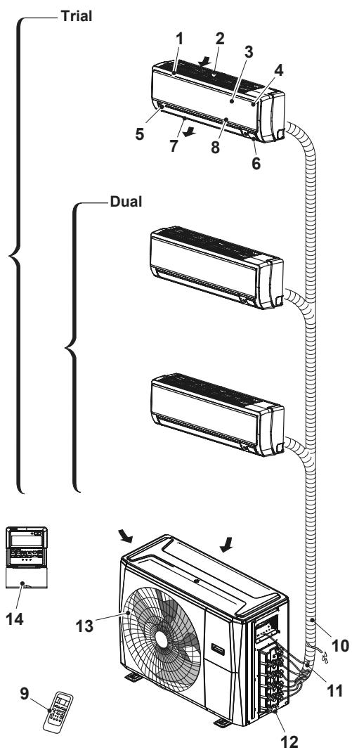
3 - APPLIANCE DESCRIPTION
3.1 - WALL INSTALLATION
Indoor unit
- Frame
- Rear air intake grille
- Front panel
- Air purifying Iter & Air Iter (behind)
- Horizontal louver
- LCD display
- Vertical louver
- Manual control button (behind)
- Remote control
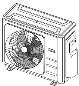
Outdoor unit
- Connection tube
- Connection cables
- Stop valve
- Fan casing
- Wall commands (optional)
EN - 7
For multi-split type air conditioners, one outdoor unit can be matched to different types of indoor units. All of the pictures in this manual are for demonstration purposes only. Your air conditioner may be slightly different, if similar in shape. The following pages introduce several kinds of indoor units that can be matched with the outdoor units.
3.2 - MINIMUM AMBIENT AREA IN THE CASE OF REFRIGERANT GAS LOADING
When your air conditioner is used outside of the following temperature ranges, certain safety protection features may activate and cause the unit to disable.
| COOL mode | HEAT mode | DRY mode | |
| Room Temperature | 17 °C / 32 °C | 0 °C / 30 °C | 10 °C / 32 °C |
| Outdoor Temperature | 0 °C / 50 °C | -15 °C / 24 °C | 0 °C / 50 °C |
| -15 °C / 50 °C(For models with low temp. cooling systems.) | |||
| 0 °C / 52 °C(For special tropical models) | 0 °C / 52 °C(For special tropical models) |
Relative humidity of the room lower than 80%. If relative humidity is higher than this value, the air conditioner may generate condensation. Set the air flow of the vertical louver to its maximum angle (vertically on the floor) and set fan mode to HIGH.
To further optimize the performance of your unit, do the following:
- Keep doors and windows closed.
- Limit energy usage by using TIMER ON and TIMER OFF functions.
- Do not block air inlets or outlets.
• Regularly inspect and clean air filters.
3.4 - RECOMMENDATIONS FOR ENERGY SAVINGS
Below find simple recommendations for reducing consumption:
• Always and constantly keep the filters clean (see maintenance and cleaning chapter).
- Keep the doors and windows of the rooms to be climate controlled closed.
- Avoid the sun's rays penetrating freely into the room (we recommend using curtains or lowering blinds or closing the shutters).
- Do not obstruct the unit air flow (inlet and outlet), i.e. in addition to bad performance of the system, it also affects correct operation and the possibility of irreparable faults to the units.
• DO NOT set the unit to excessive temperature levels.
- Set a timer and use the built-in SLEEP/ECONOMY mode if applicable.
- If you don't plan to use the unit for a long time, remove the batteries from the remote control.
- Clean the air filter every two weeks. A dirty filter can reduce cooling or heating efficiency.
- Adjust louvers properly and avoid direct airflow.
- Closing curtains during heating also helps keep the heat in.
- Doors and windows should be kept closed.
4 - OPERATIONS AND MAINTENANCE
4.1 - OPERATION MODE SELECTION
While two or more indoor units are simultaneously operating, make sure the modes do not conflict with each other. The heat mode claims precedence over all other modes. If the unit initially started to operate in HEAT mode, the other units can operate in HEAT mode only.
For example:
If the unit initially started operates under COOL (or FAN) mode, the other units can operate under any mode except HEAT.
If one of the unit selects HEAT mode, the other operating units will stop operation and display "--" (for units with display window only) or the auto and operation indication light will flash rapidly, the defrost indication light will turn off, and the timer indication light will remain on (for units without a display window).
Alternatively, the defrost and alarm indication light (if applicable) will light up, or the operation indication light will flash rapidly, and the timer indication light will turn off (for the floor and standing type).
4.2 - MAINTENANCE
If you plan to leave the unit idle for a long time, perform the following tasks:
- Clean the indoor unit and air filter.
- Select FAN ONLY mode and let the indoor fan run for a time to dry the inside of the unit.
- Disconnect the power supply and remove the battery from the remote control.
- Check components of the outdoor unit periodically. Contact a local dealer or a customer service centre if the unit requires servicing.

Before you clean the air conditioner, be sure to switch o the unit and disconnect the power supply plug.
To achieve optimal performance, please note the following:
- Adjust the direction of the air flow so that it is not blowing directly on people.
- Adjust the temperature to achieve the highest possible level of comfort. Do not adjust the unit to excessive temperature levels.
- Close doors and windows in COOL mode or HEAT mode.
- Use the TIMER ON button on the remote controller to select a time you want to start your air conditioner.
- Do not place any object near the air inlet or air outlet, as the efficiency of the air conditioner may be reduced and the air conditioner may stop running.
- Clean the air filter periodically, otherwise cooling or heating performance may be reduced.
- Do not operate unit with horizontal louvre in closed position.
When the air conditioner is to be used again:
- Use a dry cloth to wipe off the dust accumulated on the rear air intake grille in order to avoid the dust being dispersed from the indoor unit.
- Check that the wiring is not broken off or disconnected.
- Check that the air filter is installed.
- Check if the air outlet or inlet is blocked after the air conditioner has not been used for a long time.
5 - TROUBLESHOOTING
5.1 - SAFETY PRECAUTIONS
If one of the following conditions occurs, switch off and promptly disconnect the appliance.
- The power cord is damaged or heats up in an abnormal manner.
• You smell a burning odour.
• The unit emits loud or abnormal sounds. - A power fuse blows or the circuit breaker frequently trips.
• Water or other objects fall inside the appliance.

IN THE PRESENCE OF THESE CONDITIONS, DO NOT TRY TO SOLVE THE ANOMALY BY YOURSELF. PROMPTLY CONTACT A RETAILER OR AN AUTHORIZED ASSISTANCE CENTRE!
5.2 - COMMON ISSUES
The following problems are not a malfunction and in most situations will not require repairs.
| Malfunctioning | Cause | What must be done? |
| The unit will not start. | Current failure | Wait for the current to be restored. |
| The unit is disconnected from the current. | Check that the plug is inserted in the wall socket. | |
| A fuse has blown. | Replace the fuse. | |
| The remote control batteries may be discharged. | Replace the batteries. | |
| The compressor 3 minute protection has activated. | Wait. | |
| The unit does not cool or heat the room well, while air escapes from the conditioner. | Incorrect temperature setting. | Set the temperature correctly. |
| The air filter is clogged. | Clean the air filter. | |
| The doors or windows are open. | Close the doors or windows. | |
| The air inlet or outlet vents of the indoor or outdoor units are blocked. | First, remove the obstructions and then re-start the unit. | |
| Temperature setting may be higher than the ambient room temperature. | Lower the temperature setting. | |
| Excessive heat generated by the sunlight. | Close your windows or curtains. | |
| Low cooling caused by leakage or prolonged use. | Check for possible leakage, contact the assistance service if that occurs. | |
| The outdoor temperature is lower than 7°C. | Check for possible leakage, contact the assistance service if that occurs. | |
| Low refrigerant due to leak or long-term use. | Check for possible leakage, contact the assistance service if that occurs. | |
| The unit starts and stops frequently | There's too much or too little refrigerant in the system. | Check for possible leakage, contact the assistance service if that occurs. |
| There is air, incompressible gas or foreign material in the refrigeration system. | Contact the assistance service. | |
| System circuit is blocked. | Contact the assistance service. | |
| The compressor is broken. | Contact the assistance service. | |
| The voltage is too high or too low. | Install a manostat to regulate the voltage; contact the assistance service. |
5.3 - FUNCTIONAL ASPECTS NOT TO BE MISTAKEN FOR ANOMALIES
The following events may occur during normal operation:
1. PROTECTION OF THE AIR CONDITIONER.
a. The compressor will not re-start for 3 minutes after it has been switched off.
- The unit is designed not to blow cold air in HEATING mode, when the internal heat exchanger is in one of the following conditions and the temperature set has not been reached.
- When heating has just been started.
- Defrosting.
- Low temperature heating.
b. The indoor or outdoor fans stop running during defrosting.
- Frost may form on the outdoor unit during the heating cycle, when the outdoor temperature is low and humidity is high, which may cause lower heating efficiency or air conditioning.
- If this occurs, the air conditioner will stop heating mode and will automatically activate the defrosting function.
- The time required to perform defrosting can vary from 4 to 10 minutes, depending on the outdoor temperature and the amount of frost that has formed on the outdoor unit.
2. WHITE MIST ESCAPES FROM THE INDOOR UNIT
- White mist may be generated due to the large temperature difference between the inlet air and the outlet air in COOLING mode in indoor environments with high relative humidity.
- The white mist may be generated by the humidity produced by the defrosting process when the air conditioner re-starts in COOLING mode after defrosting.
3. SLIGHT AIR CONDITIONER NOISE
- A low hissing noise may be heard when the compressor is running, or has just been switched off. It is the noise of the refrigerant running or stopping.
- A low “squeaking” noise may also be heard when the compressor is running, or has just been switched off. This is caused by expansion due to the heat or contraction due to cold of the plastic parts of the unit, when the temperature changes.
- A noise may be heard due to the louvre restoring itself to its original position on commissioning.
4. DUST IS BLOWN OUT FROM THE INDOOR UNIT.
- This is normal when the air conditioner is re-started after a long period of inactivity, or is used for the first time.
5. A STRANGE ODOUR IS DETECTED COMING FROM THE INDOOR UNIT.
- It is caused by the indoor unit, which releases the odours absorbed by the construction materials, the furnishings or from smoking.
6. THE AIR CONDITIONER GOES TO FAN ONLY MODE FROM HEATING AND COOLING MODE
- When the indoor temperature reaches the temperature set on the air conditioner, the compressor stops automatically and the air conditioner goes to fan only mode. The compressor will start again, when the indoor temperature increases in cooling mode, or lowers in heating mode.
7. POSSIBLE DRIPPING OF WATER.
- Droplets of water may form on the surface of the indoor unit when cooling is activated in high relative humidity conditions (relative humidity above 80%).
Adjust the horizontal louvre to maximum opening to allow the air to escape and select high fan speed.
8. HEATING MODE
- The air conditioner takes heat from the outdoor unit and releases it through the indoor unit during operation in heating mode. When the outdoor temperature lowers, the heat introduced by the air conditioner consequently decreases.
- Simultaneously, the air conditioner heat production load increases due to the greater difference between the indoor and outdoor temperatures.
- If a comfortable temperature cannot be obtained only with the air conditioner, it is recommended to use an additional heating device.
9. AUTOMATIC RE-START FUNCTION
- The indoor unit has an automatic re-start button (auto-reset). Whenever there is unexpected power failure, the settings present at the time of the voltage drop will be restored. The unit will automatically re-activate the previous operational settings after 3 minutes from the voltage being restored.
10. LIGHTENING OR ELECTRIC EQUIPMENT
- Lightening or wireless phones working in the vicinity could cause the air conditioner to malfunction.
6 - ACCESSORIES

An incorrect installation may cause water leakage, electric shocks and fire, or cause a malfunction of the equipment.
| Name of Accessories | Q'ty (pc) | Shape |
| Manual | 2~4 |  |
| Installation plate (some models) | 1 |
| Name of Accessories | Q'ty (pc) | Shape |
| Plastic expansion sheath (some models) | 5-8 (depending on models) | |
| Self-Tapping Screw A (some models) | 5-8 (depending on models) | |
| Transfer connector (packed with the indoor or outdoor unit, depending on models)NOTE: Pipe size may differ from appliance to appliance. To meet different pipe size requirements, sometimes the pipe connections need a transfer connector installed on the outdoor unit. | Optional part (one piece/ one indoor unit) | 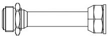 |
| Optional part (1-5 pieces for outdoor unit, depending on models) | ||
| Drain joint (some models) | 1 | 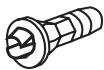 |
| Seal ring (some models) | 1 | 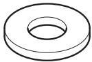 |
| Name of Accessories | Q'ty (pc) | Shape |
| Magnetic ring (Hitch it on the connective cable between indoor unit and outdoor unit after installation.) (some models) | Varies by model |  |
| Cord protection rubber ring (If the cord clamp cannot fasten on a small cord, use the cord protection rubber ring [supplied with accessories] to wrap around the cord. Then fix it in place with the cord clamp.) (some models) | 1 | 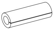 |
OPTIONAL
| Name | Forma | Quantità (PC) | |
| Connecting pipe assembly. | Liquid side | ∅6.35 (1/4 in) | Parts you must purchase separate. |
| ∅9,52 (3/8 in) | |||
| Gas side | ∅9,52 (3/8 in) | ||
| ∅12.7 (1/2 in) | |||
| ∅ 16 (5/8 in) | |||
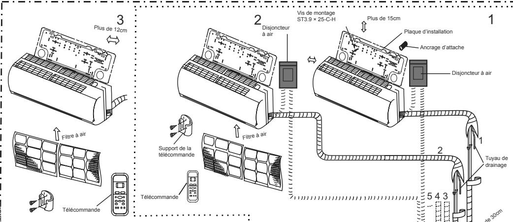
7 - INSTALLATION
7.1 - PROCEDURES FOR INSTALLATION
natural_image
Line drawing of a multi-compartment air conditioner unit with fan blades (no text or symbols)• Install the outdoor unit
natural_image
Diagram of a mechanical clamp tool interacting with a cylindrical component (no text or symbols present)- Connect the refrigerant pipes
- Connect the wires
natural_image
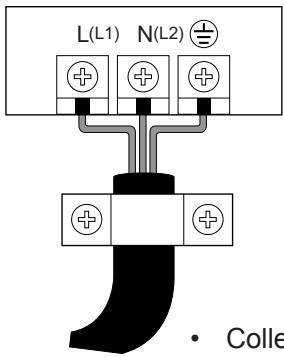
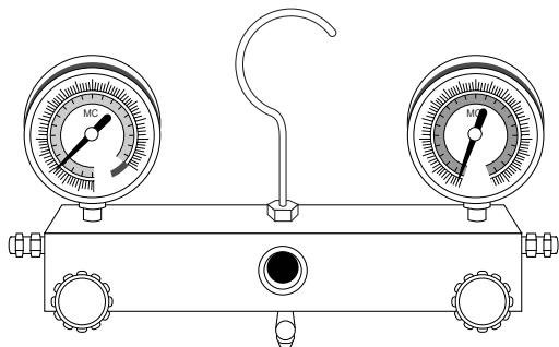
Line drawing of a dual-gauge pressure regulator with a hook and valve (no text or symbols)• Evacuate the refrigeration system

natural_image
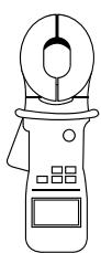
Line drawing of a handheld electronic device with a coiled cable and bulb (no text or symbols)
- Perform a test run
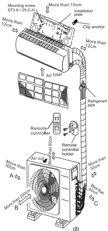
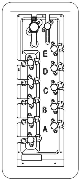
7.2 - INSTALLATION DIAGRAM
..... Dual
--- Trial
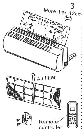
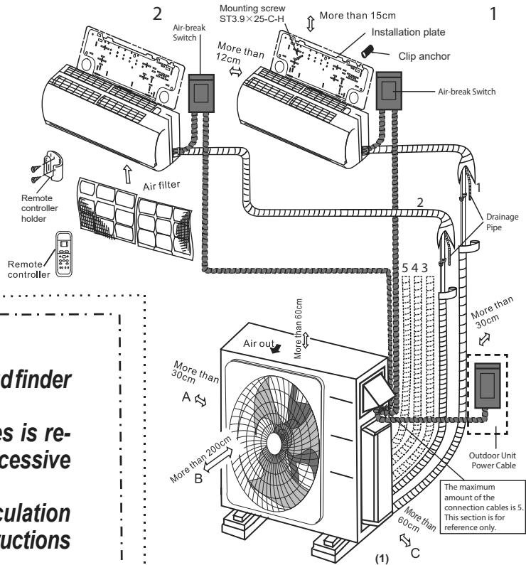

• To prevent wall damage, use a stud finder to locate studs.
- A minimum pipe run of 3 metres is required to minimise vibration & excessive noise.
- Two of the A, B, and C air circulation pathways must be free from obstructions at all times.
- This illustration is for demonstration purposes only.
- The actual shape of your air conditioner may be slightly different.
• Copper lines must be independently insulated.

The installation must be performed in accordance with the requirement of local and national standards. The installation may be slightly different in different areas.
7.2.1 - Specifications
| Number of units that can be used together | Connected units | 1-5 units |
| Compressor stop/start frequency | Stop time | 3 min or more |
| Power source voltage | voltage fluctuation | ±10% of rated voltage |
| voltage drop during start | ±15% of rated voltage | |
| interval unbalance | ±3% of rated voltage |
Unit: m
| Dual | Trial | |
| Max. length for all rooms | 40 | 60 |
| Max. length for one indoor unit | 25 | 30 |
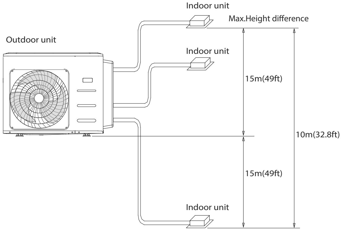
| Max. height different between indoor and outdoor unit | 15 | 15 |
| Max. height different between indoor units | 10 | 10 |

For the units adopt quick connectors, no more than two pipes can be connected, and the Max. length for each pipe is 7.5 meters.
When installing multiple indoor units with a single outdoor unit, ensure that the length of the refrigerant pipe and the drop height between the indoor and outdoor units meet the requirements illustrated in the following diagram:
7.3 - OUTDOOR UNIT INSTALLATION
Install the unit by following local codes and regulations, there may be differ slightly between different regions.
7.3.1 - Step 1: Select installation location
Before installing the outdoor unit, you must choose an appropriate location. The following are standards that will help you choose an appropriate location for the unit.
Proper installation locations meet the following standards:
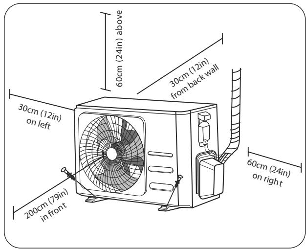
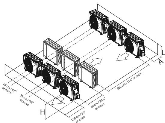
- Keep the distances indicated in the figure.
• Good air circulation and ventilation. - Stable and levelled supporting surface.
• The unit noise must not disturb others. - Fixing wall able to bear the unit.
- Where snowfalls are envisaged, adopt appropriate measures to prevent ice accumulation and damages to the unit.
DO NOT install unit in the following locations:
• Near an obstacle which may obstruct the air inlet or outlet.
- Near a public street, crowded areas, or where noise from the unit will disturb others
• Near animals or plants that will be harmed by hot air discharge
- Near any source of combustible gas In a location that is exposed to large amounts of dust
• In a location exposed to a excessive amounts of salty air
7.3.2 - Special considerations for extreme weather
If the unit is exposed to heavy wind:
Install unit so that air outlet fan is at a 90^ angle to the direction of the wind. If needed, build a barrier in front of the unit to protect it from extremely heavy winds.
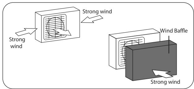
If the unit is frequently exposed to heavy rain or snow:
Build a shelter above the unit to protect it from the rain or snow. Be careful not to obstruct air flow around the unit.
If the unit is frequently exposed to salty air (seaside):
Use outdoor unit that is specially designed to resist corrosion.
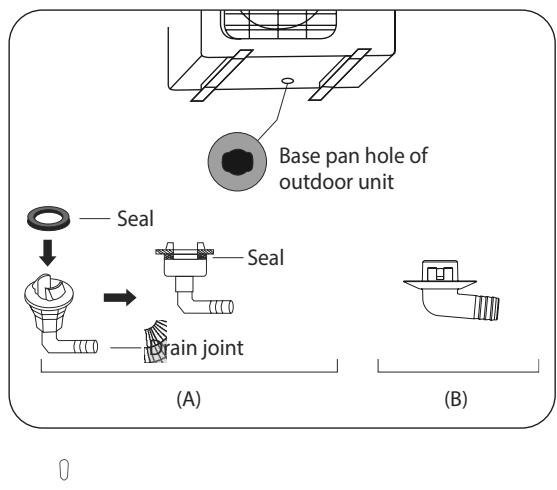
7.3.3 - Step 2: Install drain joint (Heat pump unit only)
Before bolting the outdoor unit in place, you must install the drain joint at the bottom of the unit. Note that there are two different types of drain joints depending on the type of outdoor unit.
If the drain joint comes with a rubber seal (see Fig. A), do the following:
- Position the seal on the drain joint.
- Insert the joint on the hole located on the external base of the unit.
- Turn the joint 80^ until you hear the click and place it frontally.
- Connect a drain tube to the joint (not supplied) and direct it into a catch pit.
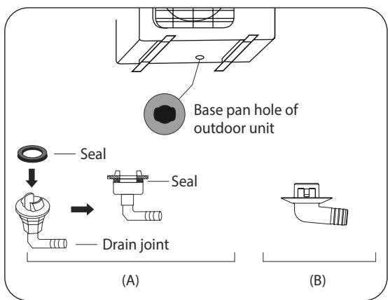
If the drain joint doesn't come with a rubber seal (see Fig.B), do the following:
- Insert the joint onto the hole located on the base of the external unit.
- Turn the joint 80^ until you hear the click and position it frontally.
- Connect a drain tube to the joint (not supplied) and direct it into a catch pit.

In cold climates, make sure the drain tube is as vertical as possible to ensure quick drainage of water. If water drains too slowly, it may freeze in the tube and damage the unit.
7.3.4 - Step 3: Anchor outdoor unit
The outdoor unit can be anchored to the ground or to a wall-mounted bracket with bolt (M10). Prepare the installation base of the unit according to the dimensions below.
7.4 - UNIT MOUNTING DIMENSIONS
The following is a list of different outdoor unit sizes and the distance between their mounting feet. Prepare the installation base of the unit according to the dimensions below.
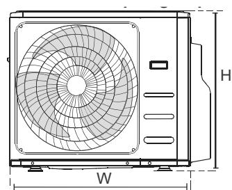
natural_image
Technical line drawing of a front-end air conditioner unit with fan and ventilation grilles, labeled with dimension H and W (no text or symbols beyond labels)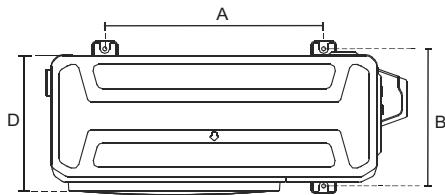
| Outdoor Unit DimensionsW × H × D (mm) | Mounting Dimensions (mm) | |
| Distance A | Distance B | |
| 940x10x410 | 673 | 403 |
| 800x554x330 | 511 | 317 |
| 890x673x342 | 663 | 354 |

The relations between H, A and L are as follows.
| L | A | |
| L ≤ H | L ≤ 1/2H | 25 cm / 9.8" or more |
| 1/2H < L ≤ H | 30 cm / 11.8" or more | |
| L >H | Can not be installed | |
7.5 - NOTES ON DRILLING HOLE IN WALL
It is necessary to drill a hole into the wall for the passage of the refrigerant piping and of the signal cable between the internal and external units.
- Determine the position of the hole in the wall based on the position of the external unit.
- Drill a hole in the wall of at least 65mm.

When drilling the wall hole, make sure to avoid wires, plumbing, and other sensitive components.
- Protect the hole edges to preserve the tubes and the cables.
| Indoor Unit capacity (Btu/h) | Liquid (in) | Gas (in) | |
| 9K/12K | 1/4 | 3/8 | |
| 12K | 1/4 | 1/2 | |
7.6 - REFRIGERANT PIPING CONNECTION
When connecting refrigerant piping, do not let substances or gases other than the specified refrigerant enter the unit.
The presence of other gases or substances will lower the unit's capacity, and can cause abnormally high pressure in the refrigeration cycle.
This can cause explosion and injury.

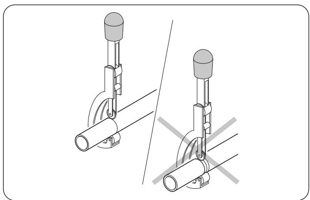
- The branching pipe must be installed horizontally. An angle of more than 10^ may cause malfunction.
• DO NOT install the connecting pipe until both indoor and outdoor units have been installed.
• Insulate both the gas and liquid piping to prevent water leakage.
7.6.1 - Step 1: Cut pipes
When preparing refrigerant pipes, take extra care to cut and flare them properly. This will ensure efficient operation and minimize the need for future maintenance.
- Measure the distance between the indoor and outdoor units.
- Cut the piping sections abounding by approximately 3 ÷ 4 cm on the length.

Use a wheel pipe cutter only to cut the pipes clamping it in short lengths so as not to crush the pipe.

NEVER USE A NORMAL HANDSAW, scraps could fall inside the pipe and enter the circuitry of the system, damaging the parts severely.
natural_image
Technical illustration of two mechanical clamping devices with no visible text or symbols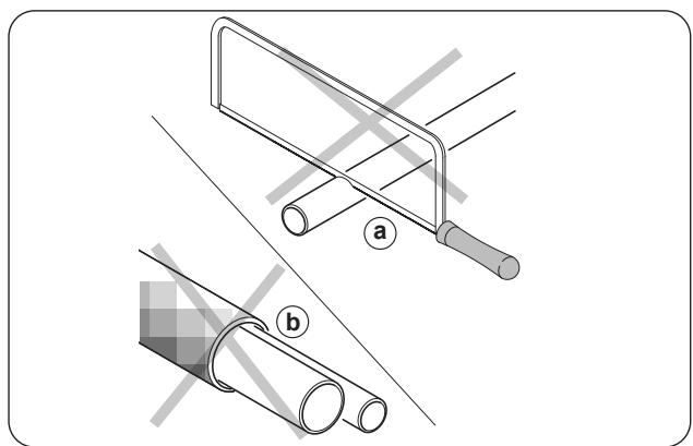
natural_image
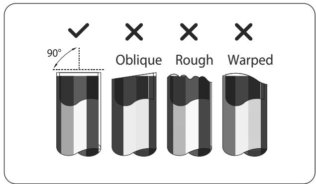
Technical illustration showing two pipe fittings with labeled parts (a and b), no text or symbols present.EN - 18
- Make sure that the pipe is cut at a perfect 90^ angle.

DO NOT DEFORM PIPE WHILE CUTTING.

Be extra careful not to damage, dent, or deform the pipe while cutting. This will drastically reduce the heating efficiency of the unit.
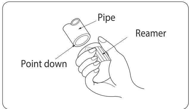
7.6.2 - Step 2: Remove burrs
Burrs can affect the air-tight seal of refrigerant piping connection. They must be completely removed.
- Hold the pipe at a downward angle to prevent burrs from falling into the pipe.
- Using a reamer or deburring tool, remove all burrs from the cut section of the pipe.
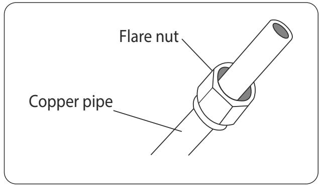
7.6.3 - Step 3: Flare pipe ends
Proper flaring is essential to achieve an airtight seal.
- After removing burrs from cut pipe, seal the ends with PVC tape to prevent foreign materials from entering the pipe.
- Sheath the pipe with insulating material.
- Place flare nuts on both ends of pipe. Make sure they are facing in the right direction, because you can't put them on or change their direction after flaring.
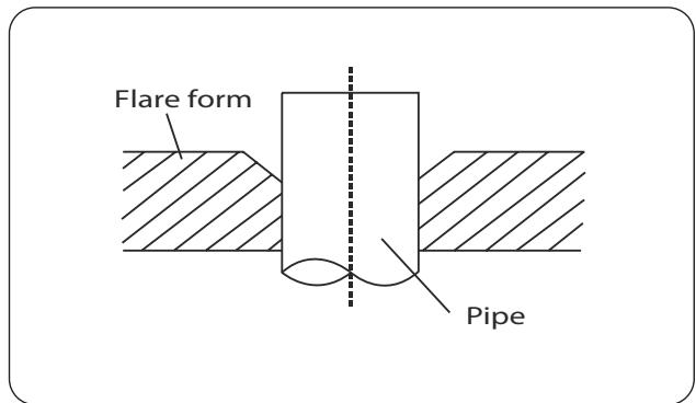
- Remove PVC tape from ends of pipe when ready to perform flaring work.
- Position the pipe into the flare form. The end of the pipe must extend beyond the flare form.
- Turn the handle of the flaring tool clockwise until the pipe is fully flared.
| Pipe gauge | Tightening torque | Flare dimension (A) (Unit: mm/Inch) | Flare shape | |
| Min. | Max. | |||
| ∅ 6.4 | 18-20 N.m (183-204 kgf.cm) | 8.4/0.33 | 8.7/0.34 | 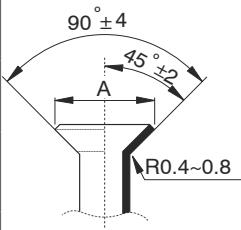 |
| ∅ 9.5 | 25-26 N.m (255-265 kgf.cm) | 13.2/0.52 | 13.5/0.53 | |
| ∅ 12.7 | 35-36 N.m (357-367 kgf.cm) | 16.2/0.64 | 16.5/0.65 | |
| ∅ 15.9 | 45-47 N.m (459-480 kgf.cm) | 19.2/0.76 | 19.7/0.78 | |
| ∅ 19.1 | 65-67 N.m (663-683 kgf.cm) | 23.2/0.91 | 23.7/0.93 | |
| ∅ 22 | 75-85N.m (765-867 kgf.cm) | 26.4/1.04 | 26.9/1.06 | |
- Remove the flaring tool and flare form, then inspect the end of the pipe for cracks and even flaring.
7.6.4 - Step 4: Connect pipes
Connect the copper pipes to the indoor unit first then connect it to the outdoor unit. You should first connect the low-pressure pipe, then the high-pressure pipe.
- When connecting the flare nuts, apply a thin coat of refrigeration oil to the flared ends of the pipes.
- Align the centre of the two pipes that you will connect.
- Tighten the flare nut as tightly as possible by hand.
- Using a spanner, grip the nut on the unit tubing.
- While firmly gripping the nut, use a torque wrench to tighten the flare nut according to the torque values in above table.
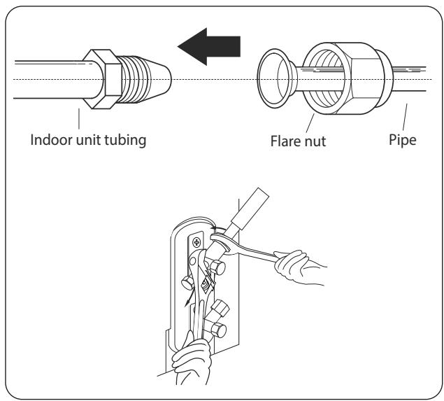

Use both a spanner and a torque wrench when connecting or disconnecting pipes to/from the unit.

- Ensure to wrap insulation around the piping. Direct contact with the bare piping may result in burns or frostbite.
• Make sure the pipe is properly connected.

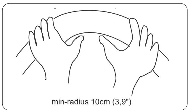
Carefully bend the tubing in the middle according to the diagram below. DO NOT bend the tubing more than 90^ or more than 3 times.
Bend the pipe using your hands.
- After connecting the copper pipes to the indoor unit, wrap the power cable, signal cable and the piping together with binding tape.

DO NOT intertwine signal cable with other wires.
EN - 20
- Thread this pipeline through the wall and connect it to the outdoor unit.
- Insulate all the piping, including the valves of the outdoor unit.
- Open the stop valves of the outdoor unit to start the flow of the refrigerant between the indoor and outdoor unit.

Check that there is no leakage of refrigerant after completing installation operations. In the event of leakage of refrigerant, immediately ventilate the area and evacuate the system.
8 -

WIRING
- All wiring must comply with local and national electrical codes, regulations and must be installed by a licensed electrician.
- All electrical connections must be made according to the Electrical Connection Diagram located on the panels of the indoor and outdoor units.
- If there is a serious safety issue with the power supply, stop work immediately. Explain your reasoning to the client, and refuse to install the unit until the safety issue is properly resolved.
- Power voltage should be within 90-110% of rated voltage. Insufficient power supply can cause malfunction, electrical shock, or re.
- Only connect the unit to an individual branch circuit outlet. Do not connect another appliance to that outlet.
• Make sure to properly ground the air conditioner. - Every wire must be firmly connected. Loose wiring can cause the terminal to overheat, resulting in product malfunction and possible re.
- Do not let wires touch or rest against refrigerant tubing, the compressor, or any moving parts within the unit.
- If the unit has an auxiliary electric heater, it must be installed at least 1 meter away from any combustible materials.
• Make sure that you do not cross your electrical wiring with your signal wiring.
• This may cause distortion and interference. - The unit must be connected to the main outlet. Normally, the power supply must have a impedance of 32 ohms.
• No other equipment should be connected to the same power circuit. - Connect the outdoor wires before connecting the indoor wires.

MAKE SURE THAT:
- The power supply voltage and frequency values respect that specified on the appliance data plate.
- The power supply line has an effective earth connection and it is correctly dimensioned for maximum absorption of the climate control unit.
- A suitable omnipolar disconnection device must be envisioned on the appliance mains electric power supply, in compliance with the national installation rules.
It must be checked that the electric power supply has an effective earth and suitable protections against overloads and/or short circuits.
The use of a ceramic fuse of the characteristics shown in the table is advised (or other devices with the same functions). - BEFORE MAKING THE ELECTRIC CONNECTION, MAKE SURE THAT THE UPSTREAM ISOLATING SWITCH IS AT "0" (OFF) AND THE PROTECTIONS OF THE INDOOR AND OUTDOOR UNITS ARE POSITIONED CORRECTLY.

BEFORE PERFORMING ANY ELECTRICAL OR WIRING WORK, TURN OFF THE MAIN POWER TO THE SYSTEM.
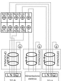
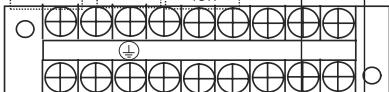
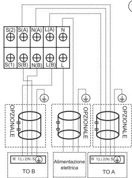
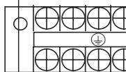
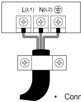
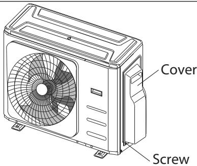
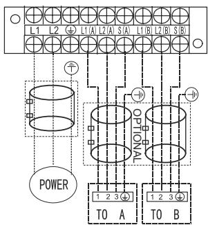
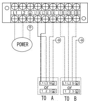
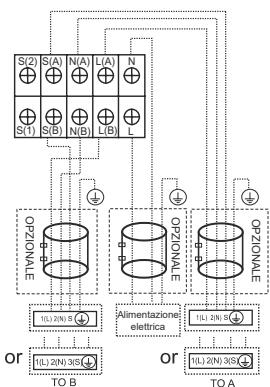
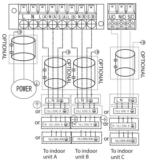
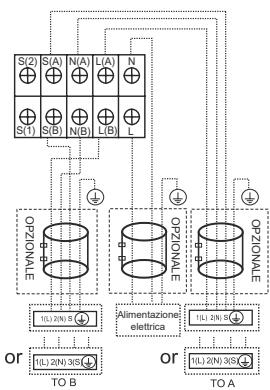
8.1 - EXTERNAL UNIT WIRING
- Remove the junction box cover of the external unit.
- Connect the cables to the terminals. Pair the colours / labels of the wire with the labels on the terminal box.
- Tighten the single terminals.
- Insulate the unused wires with electric tape. Keep them away from possible electric or metallic parts.
- Reposition the cover of the junction box.

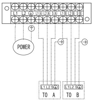
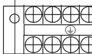
Connect the connective cables to the terminals, as identified, with their matching numbers on the terminal block of the indoor and outdoor units. For example, Terminal L1(A) of the outdoor unit must connect with terminal L1/1 on the indoor unit. The outdoor unit can match different types of indoor unit, the numbers on the terminal block of the indoor unit may be slightly different. Please pay special attention while connecting the wire.
√
√
x
DUAL
flowchart
graph TD
    subgraph Inputs
        S1["S(1)"] --> OZIONALE["OPZIONALE"]
        S2["S(2)"] --> OZIONALE
        S3["S(A)"] --> OZIONALE
        S4["N(A)"] --> OZIONALE
        S5["N(A)"] --> OZIONALE
        S6["L(A)"] --> OZIONALE
        S7["L(A)"] --> OZIONALE
    end
    OZIONALE --> TOB["TO B"]
    OZIONALE --> TOA["TO A"]
    OZIONALE --> ALIMENTAZIONE["Alimentazione elettrica"]
    OZIONALE --> TOB
    OZIONALE --> TOA
    style OZIONALE fill:#f9f,stroke:#333
    style TOB fill:#ccf,stroke:#333
    style TOA fill:#cfc,stroke:#333

flowchart
graph TD
    S1["S(1)"] --> L8["L(8)"]
    S2["S(2)"] --> L8["L(8)"]
    S3["S(A)"] --> L8["L(8)"]
    S4["N(A)"] --> L8["L(8)"]
    S5["L(A)"] --> L8["L(8)"]
    L8["L(8)"] --> L
    L8["L(8)"] --> L2["L(8)"]
    L2["L(8)"] --> L2a["L(8)"]
    L2["L(8)"] --> L2b["L(8)"]
    L2["L(8)"] --> L2c["L(8)"]
    L2["L(8)"] --> L2d["L(8)"]
    L2L["OPZIONALE"] --> TOB["TO B"]
    L2L["OPZIONALE"] --> TOA["TO A"]
    style L2L fill:#f9f,stroke:#333
    style L2L fill:#ccf,stroke:#333
    style TOB fill:#dfd,stroke:#333
    style TOA fill:#dfd,stroke:#333
    style TOB fill:#dfd,stroke:#333
    style TOA fill:#dfd,stroke:#333

flowchart
graph TD
    subgraph Top_Layer
        S2["S(2)"] --> S1["S(1)"]
        S3["S(A)"] --> S4["S(B)"]
        S5["N(A)"] --> S6["N(B)"]
        S7["L(A)"] --> S8["L(B)"]
        S9["N"] --> S10["S(B)"]
        S11["S(1)"] --> S12["S(B)"]
        S13["S(1)"] --> S14["S(B)"]
        S15["N(A)"] --> S16["N(B)"]
        S17["L(A)"] --> S18["L(B)"]
        S19["L"] --> S20["L(B)"]
    end

    subgraph Bottom_Layer
        W1["W 1L/2IN S"] --> TOB["TO B"]
        W2["W 1L/2IN S"] --> TOA["TO A"]
        W3["W 1L/2IN S"] --> TOA
        W4["W 1L/2IN S"] --> TOA
    end

    S2 -->|OPZIONALE| W1
    S3 -->|OPZIONALE| W2
    S4 -->|OPZIONALE| W3
    S5 -->|OPZIONALE| W4
    S6 -->|OPZIONALE| W5
    S7 -->|OPZIONALE| W6
    S8 -->|OPZIONALE| W7
    S9 -->|OPZIONALE| W8
    S10 -->|OPZIONALE| W9
    S11 -->|OPZIONALE| W10
    S12 -->|OPZIONALE| W11
    S13 -->|OPZIONALE| W12
    S14 -->|OPZIONALE| W13
    S15 -->|OPZIONALE| W14
    S16 -->|OPZIONALE| W15
    S17 -->|OPZIONALE| W16
    S18 -->|OPZIONALE| W17
    S19 -->|OPZIONALE| W18
    S20 -->|OPZIONALE| W19
    W1 & W2 & W3 & W4 & W5 & W6 & W7 & W8 & W9 & W10 & W11 & W12 & W13 & W14 & W15 & W16 & W17 & W18 & W19 & W20 & W21 & W22 & W23 & W24 & W25 & W26 & W27 & W28 & W29 & W30 & W31 & W32 & W33 & W34 & W35 & W36 & W37 & W38 & W39 & W40 & W41 & W42 & W43 & W44 & W45 & W46 & W47 & W48 & W49 & W50 & W51 & W52 & W53 & W54 & W55 & W56 & W57 & W58 & W59 & W60 & W61 & W62 & W63 & W64 & W65 & W66 & W67 & W68 & W69 & W70 & W71 & W72 & W73 & W74 & W75 & W76 & W77 & W78 & W79 & W80 & W81 & W82 & W83 & W84 & W85 & W86 & W87 & W88 & W89 & W90 & W91 & W92 & W93 & W94 & W95 & W96 & W97 & W98 & W99 & X-axis label: TO B, Alimentazione elettrica, TO A, TO B, TO C, TO D, TO E, TO F, TO G, TO H, TO I, TO J, TO K, TO L, TO M, TO N, TO O, TO P, TO Q, TO R, TO S, TO T, TO U, TO V, TO V, TO A, TO A', Y-axis label: OPZIONALE, ALIMENTAZIONE ELECTRICA, TO B, TO C, TO D, TO E, TO F, TO G, TO H, TO I, TO J, TO K, TO L, TO M, TO N, TO P, TO Q, TO R, TO S, TO T, TO U, TO V, TO Z.
TRIAL

flowchart
graph TD
    subgraph Power
        A["POWER"] --> B["Optional Unit A"]
        A --> C["Optional Unit B"]
        A --> D["Optional Unit C"]
    end

    subgraph To Indoor Unit A
        E["To indoor unit A"] --> F["1(L) 2(N) S"]
        G["To indoor unit B"] --> H["1(L) 2(N) S"]
        I["To indoor unit C"] --> J["1(L) 2(N) 3(S)"]
    end

    subgraph To Indoor Unit B
        K["To indoor unit B"] --> L["1(L) 2(N) S"]
        M["To indoor unit C"] --> N["1(L) 2(N) 3(S)"]
    end

    subgraph To Indoor Unit C
        O["To indoor unit C"] --> P["1(L) 2(N) S"]
        Q["To indoor unit C"] --> R["1(L) 2(N) 3(S)"]

Once the previously described conditions are met, follow these guidelines when the wiring is carried out:
- Always have an individual power circuit specifically for the air conditioner. Always follow the circuit diagram posted on the inside of the control cover.
- Screws fastening the wiring in the casing of electrical fittings may come loose during transportation. Because loose screws may cause wire burn-out, check that the screws are tightly fastened.
- Check the specifications for the power source.
- Confirm that electrical capacity is sufficient.
- Confirm that starting voltage is maintained at more than 90 percent of the rated voltage marked on the name plate.
- Confirm that the cable thickness is as specified in the power source specifications.
• Always install an earth leakage circuit breaker in wet or moist areas. - The following can be caused by a drop in voltage: vibration of a magnetic switch, damaging the contact point, broken fuses, and disturbance of normal functioning.
- Disconnection from a power supply must be incorporated into the fixed wiring. It must have an air gap contact separation of at least 3mm in each active (phase) conductors.
• Before accessing terminals, all supply circuits must be disconnected.
9 - AIR EVACUATION
Air and foreign matter in the refrigerant circuit can cause abnormal rises in pressure, which can damage the air conditioner, reduce its efficiency, and cause injury.
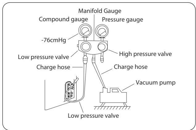
Use a vacuum pump and manifold gauge to evacuate the refrigerant circuit, removing any non-condensable gas and moisture from the system.
Evacuation should be performed upon initial installation and when unit is relocated.
BEFORE PERFORMING EVACUATION
- Check to make sure the connective pipes between the indoor and outdoor units are connected properly.
- Check to make sure all wiring is connected.
Before using a manifold gauge and a vacuum pump, read their operation manuals to make sure you know how to use them properly.
- Connect the manifold gauge charge hose to the service port on the outdoor unit's low pressure valve.
- Connect the manifold gauge charge hose from the to the vacuum pump.
- Open the Low Pressure side of the manifold gauge. Keep the High Pressure side closed.
- Turn on the vacuum pump to evacuate the system.
- Run the vacuum for at least 15 minutes, or until the Compound Meter reads -76cmHG (-1x10⁵Pa).
- Close the manifold gauge Low Pressure valve and turn off the vacuum pump.
- Wait for 5 minutes, then check that there has been no change in system pressure.

If there is no change in system pressure, unscrew the cap from the packed valve (high pressure valve). If there is a change in system pressure, there may be a gas leak.
- Insert hexagonal wrench into the packed valve (high pressure valve) and open the valve by turning the wrench 1/4 counterclockwise. Listen for gas to exit the system, then close the valve after 5 seconds.
- Watch the Pressure Gauge for one minute to make sure that there is no change in pressure. It should read slightly higher than the atmospheric pressure.
- Remove the charge hose from the service port.
- Using hexagonal wrench, fully open both the high pressure and low pressure valves.
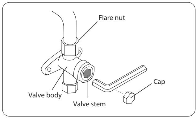

OPEN VALVE STEMS GENTLY
When opening valve stems, turn the hexagonal wrench until it hits against the stopper. DO NOT try to force the valve to open further.
- Tighten valve caps by hand, then tighten it using the proper tool.
- If the outdoor unit uses all vacuum valves, and the vacuum position is at the main valve, the system is not connected with the indoor unit. The valve must be tightened with a screw nut. Check for gas leaks before operation to prevent leakage.

• After confirmation of the above conditions, follow these guidelines when performing wiring:
• Refrigerant charging must be performed after wiring, vacuuming, and the leak testing.
- DO NOT exceed the maximum allowable quantity of refrigerant or overcharge the system. Doing so can damage the unit or impact it's functioning.
- Charging with unsuitable substances may cause explosions or accidents. Ensure that the appropriate refrigerant is used.
- Refrigerant containers must be opened slowly. Always use protective gear when charging the system.
• DO NOT mix refrigerants types.
- For the R32 refrigerant model, make sure the conditions within the area have been made safe by control of flammable material when the refrigerant added into air conditioner.
Depending on the length of connective piping or the pressure of the evacuated system, you made need to add refrigerant. Refer to table below for refrigerant amounts to be added:
| Connective Pipe Length (m) | Air Purging Method | Additional Refrigerant | |
| More than (pre-charge pipe lengthxN) m | Vacuum Pump | Liquid Side: ∅ 6,35 (∅ 1/4") (Total pipe length - pre-charge pipe length xN) x12g/m | Liquid Side: ∅ 9,52 (∅ 3/8") (Total pipe length - pre-charge pipe length xN) x12g/m |

The standard pipe length is 7.5m.
9.1 - INSTALLATION DIAGRAM
Perform the electrical safety check after completing installation. Cover the following areas:
- Insulated resistance The insulated resistance must be more than 2MΩ.
- Grounding work
After finishing grounding work, measure the grounding resistance by visual detection and using the grounding resistance tester.
Make sure the grounding resistance is less than 4 .
- Electrical leakage check (performing during test while unit is on)
During a test operation after completed installation, the use the electroprobe and multimeter to perform an electrical leakage check. Turn off the unit immediately if leakage happens. Try and evaluate different solutions until the unit operates properly.
Gas leak check
- Soap water method:
Apply a soap-water solution or a liquid neutral detergent on the indoor unit connection or outdoor unit connections with a soft brush to check for leakage of the connecting points of the piping. If bubbles emerge, the pipes are experiencing leakage.
- Leak detector
Use the leak detector to check for leakage.

The illustration is for example purposes only. The actual order of A, B and C on the machine may be slightly different from the unit you purchased but the general shape will remain the same.
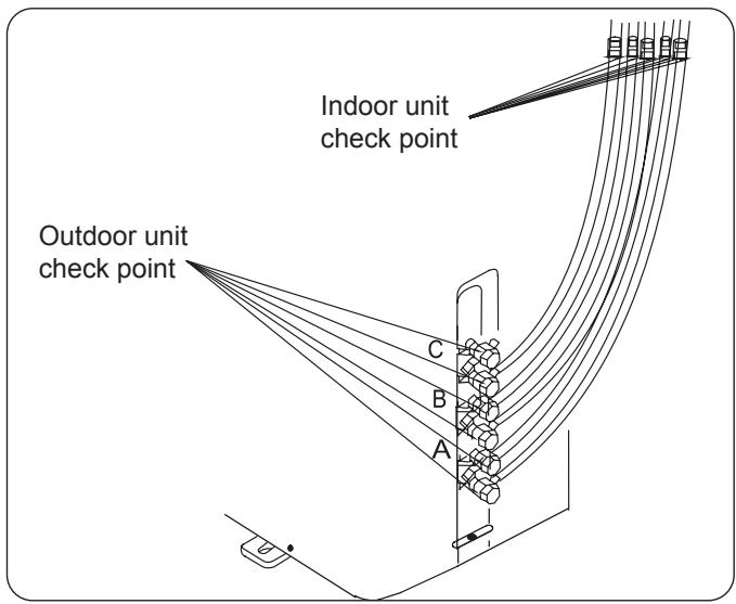
A, B are points for DUAL type. A, B and C are points for the TRIAL type.
9.2 - TEST RUN
A test run must be performed after the entire system has been completely installed. Confirm the following points before performing the test:
a) The indoor and outdoor units are properly installed.
b) Piping and wiring are properly connected.
c) No obstacles near the inlet and outlet of the unit that might cause poor performance or product malfunction.
d) The refrigeration system does not leak.
e) Drainage system is unimpeded and draining to a safe location.
f) The heating insulation is properly installed.
g) The grounding wires are properly connected.
h) Length of the piping and additional refrigerant stow capacity have been recorded.
i) The power voltage is the correct voltage for the air conditioner.

Failure to perform the test run may result in unit damage, property damage or personal injury.
- Open both the liquid and gas stop valves.
- Turn on the main power switch and allow the unit to warm up.
- Set the air conditioner to COOL mode.
- For the Indoor Unit
a. Ensure the remote control and its buttons work properly.
b. Ensure the louvers move properly and can be changed using the remote control.
c. Double check to see if the room temperature is being registered correctly.
d. Ensure the indicators on the remote control and the display panel on the indoor unit work properly.
e. Ensure the manual buttons on the indoor unit works properly.
f. Check to see that the drainage system is unimpeded and draining smoothly.
g. Ensure there is no vibration or abnormal noise during operation.
5. For the Outdoor Unit
a. Check to see if the refrigeration system is leaking.
b. Make sure there is no vibration or abnormal noise during operation.
c. Ensure the wind, noise, and water generated by the unit do not disturb your neighbors or pose a safety hazard.

If the unit does not work properly or does not work according to your expectations, please refer to the "Troubleshooting" section of this manual before consulting the customer service.
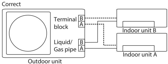
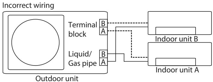
10 - FUNCTION OF AUTOMATIC WIRING/PIPING CORRECTION
More recent models now feature automatic correction of wiring/piping errors. Press the "check switch" on the outdoor unit PCB board for 5 seconds until the LED displays "CE", indicating that this function is working, Approximately 5-10 minutes after the switch is pressed, the "CE" disappears, meaning that the wiring/piping error is corrected and all wiring/piping is properly connected.
flowchart
graph TD
    A["Outdoor unit"] --> B["Terminal block"]
    A --> C["Liquid/Gas pipe"]
    B --> D["Indoor unit B"]
    C --> E["Indoor unit A"]
    D --> F["Output"]
    E --> F
    style A fill:#fff,stroke:#000
    style B fill:#fff,stroke:#000
    style C fill:#fff,stroke:#000
    style D fill:#fff,stroke:#000
    style E fill:#fff,stroke:#000

flowchart
graph TD
    A["Incorrect wiring"] --> B["Outdoor unit"]
    B --> C["Terminal block"]
    B --> D["Liquid/Gas pipe"]
    C --> E["Indoor unit B"]
    D --> F["Indoor unit A"]
    E --> G["Indoor unit B"]
    F --> H["Indoor unit A"]
flowchart
graph TD
    A["Incorrect wiring"] --> B["Outdoor unit"]
    B --> C["Terminal block"]
    B --> D["Liquid/Gas pipe"]
    C --> E["Indoor unit B"]
    D --> F["Indoor unit A"]
    E --> G["Indoor unit B"]
    F --> H["Indoor unit A"]
To activate this function:
- Check that outside temperature is above 5^ C. (This function does not work when outside temperature is not above 5^ C).
- Check that the stop valves of the liquid pipe and gas pipe are open.
- Turn on the breaker and wait at least 2 minutes.
- Press the check switch on the outdoor PCB board unit LED display "☐".
0 - SYMBOLOGIE 2
1 - MISES EN GARDE GÉNÉRALES....2
9 - ÉVACUATION D'AIR....23
9.1 - SCHÉMA D'INSTALLATION 25
9.2 - MISE EN SERVICE....25
10 - FONCTION DE LA CORRECTION AUTOMATIQUE DE CÂBLAGE/TUYAUTERIE....26

ELIMINATION
natural_image
Line drawing of a multi-compartment air conditioner unit with fan blades (no text or symbols)natural_image
Mechanical diagram showing a tool interacting with a bolt and shaft (no text or symbols)natural_image
Line drawing of a dual-gauge pressure regulator with a hook and central dial (no text or symbols)natural_image
Line drawing of a handheld electronic device with a coiled cable and bulb (no text or symbols)..... Dual
--- Trial
natural_image
Technical line drawing of a front-end air conditioner unit with fan and side-mounted buttons (no text or symbols)
| Dimensions de l'unité extérieureW × H × D (mm) | Dimensions de montage (mm) | |
| Distance A | Distance B | |
| 940x10x410 | 673 | 403 |
| 800x554x330 | 511 | 317 |
| 890x673x342 | 663 | 354 |

natural_image
Technical illustration of two mechanical clamping devices with no visible text or symbols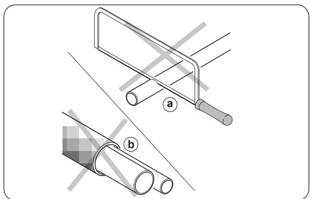
natural_image
Technical illustration showing two pipe fittings with labeled parts (a and b), no text or symbols present.FR - 18
flowchart
graph TD
    subgraph Power
        A["POWER"] --> B["Optional Unit"]
        B --> C["Optional Unit"]
        C --> D["Optional Unit"]
    end

    subgraph To Indoor Unit A
        E["To indoor unit A"] --> F["1(L) 2(N) S"]
        G["To indoor unit B"] --> H["1(L) 2(N) S"]
        I["To indoor unit C"] --> J["1(L) 2(N) 3(S)"]
    end

    subgraph To Indoor Unit B
        K["To indoor unit B"] --> L["1(L) 2(N) 3(S)"]
        M["To indoor unit C"] --> N["1(L) 2(N) 3(S)"]
    end

    subgraph To Indoor Unit C
        O["To indoor unit C"] --> P["1(L) 2(N) 3(S)"]
    end

    style Power fill:#f9f,stroke:#333
    style To Indoor Unit A fill:#ccf,stroke:#333
    style To Indoor Unit B fill:#ccf,stroke:#333
    style To Indoor Unit C fill:#ccf,stroke:#333
    style To Indoor Unit A fill:#dfd,stroke:#333
    style To Indoor Unit B fill:#dfd,stroke:#333
    style To Indoor Unit C fill:#dfd,stroke:#333
    style To Indoor Unit C fill:#dfd,stroke:#333

9 - ÉVACUATION D'AIR
1 - ALLGEMEINE WARNHINWEISE....2
1. SCHUTZ DES KLIMAGERÄTS.
natural_image
Line drawing of a multi-compartment air conditioner unit with fan blades (no text or symbols)natural_image
Diagram of a mechanical clamp tool interacting with a bolt, showing rotational motion (no text or symbols)natural_image
Line drawing of a dual-gauge pressure regulator with a hook and valve (no text or symbols)natural_image
Line drawing of a handheld device with a coiled cable and bulb (no text or symbols)natural_image
Technical line drawing of a front-end air conditioner unit with fan and side-mounted buttons (no text or symbols)
natural_image
Technical illustration of two mechanical clamping devices with no visible text or symbols
natural_image
Technical illustration showing two pipe fittings with labeled parts (a and b), no text or symbols present.DE - 18
(○)
↓
TRIAL
flowchart
graph TD
    subgraph Power
        direction TB
        L1["L N"] --> L2["L (A) N (A) S (A) L (B) N (B) S (B)"]
        L2 --> L3["+"]
        L3 --> L4["+"]
        L4 --> L5["+"]
        L5 --> L6["+"]
        L6 --> L7["+"]
        L7 --> L8["+"]
        L8 --> L9["+"]
        L9 --> L10["+"]
    end

    subgraph To Indoor Unit A
        direction TB
        L1L1["L N S+"] --> L1L2["1(L) 2(N) S+"] --> L1L3["+"]
        L1L3 --> L1L4["+"]
        L1L4 --> L1L5["+"]
        L1L5 --> L1L6["+"]
        L1L6 --> L1L7["+"]
        L1L7 --> L1L8["+"]
        L1L8 --> L1L9["+"]
    end

    subgraph To Indoor Unit B
        direction TB
        L2L2["L N S+"] --> L2L3["1(L) 2(N) S+"] --> L2L4["+"]
        L2L4 --> L2L5["+"]
        L2L5 --> L2L6["+"]
        L2L6 --> L2L7["+"]
        L2L7 --> L2L8["+"]
        L2L8 --> L2L9["+"]
    end

    subgraph To Indoor Unit C
        direction TB
        L3L3["L N S+"] --> L3L4["1(L) 2(N) S+"] --> L3L5["+"]
        L3L5 --> L3L6["+"]
        L3L6 --> L3L7["+"]
        L3L7 --> L3L8["+"]
        L3L8 --> L3L9["+"]
    end

    L1L1 --> OPOLEXP
    L1L2 --> OPOLEXP
    L1L3 --> OPOLEXP
    L1L4 --> OPOLEXP
    L1L5 --> OPOLEXP
    L1L6 --> OPOLEXP
    L1L7 --> OPOLEXP
    L1L8 --> OPOLEXP
    L1L9 --> OPOLEXP
    style Power fill:#f9f,stroke:#333
    style To Indoor Unit A fill:#ccf,stroke:#333
    style To Indoor Unit B fill:#ccf,stroke:#333
    style To Indoor Unit C fill:#ccf,stroke:#333
[Non-Text]
[Non-Text]
①

natural_image
Line drawing of a multi-compartment air conditioner unit with fan blades (no text or symbols)natural_image
Diagram of a mechanical clamp tool interacting with a bolt, showing rotational motion (no text or symbols)natural_image
Line drawing of a dual-gauge pressure regulator with a hook and central dial (no text or symbols)natural_image
Line drawing of a handheld device with a coiled cable and bulb (no text or symbols)natural_image
Technical line drawing of a front-end air conditioner unit with fan and side-mounted buttons (no text or symbols)
natural_image
Technical illustration of two mechanical clamping devices with no visible text or symbols
ES - 18
flowchart
graph TD
    subgraph Power
        L1["L"] --> L2["L(A)"]
        L3["L"] --> L4["N(A)"]
        L5["S"] --> L6["A"]
        L7["L"] --> L8["B"]
        L9["N"] --> L10["S"]
        L10["S"] --> L11["B"]
        L11 --> L12["B"]
        L12 --> L13["B"]
        L13 --> L14["B"]
    end

    subgraph To Indoor Unit A
        L1a["L N"] --> L1b["L N S"]
        L1c["1(L) 2(N) S"] --> L1d["1(L) 2(N) S"]
        L1e["or"] --> L1f["W 1(L) 2(N) S"]
        L1g["or"] --> L1h["W 1(L) 2(N) S"]
        L1i["or"] --> L1j["1(L) 2(N) 3(S)"]
        L1k["or"] --> L1l["1(L) 2(N) 3(S)"]
    end

    subgraph To Indoor Unit B
        L1m["L N"] --> L1n["L N S"]
        L1o["1(L) 2(N) S"] --> L1p["1(L) 2(N) S"]
        L1q["or"] --> L1r["W 1(L) 2(N) S"]
        L1s["or"] --> L1t["W 1(L) 2(N) S"]
        L1u["or"] --> L1v["1(L) 2(N) 3(S)"]
        L1w["or"] --> L1x["1(L) 2(N) 3(S)"]
    end

    subgraph To Indoor Unit C
        L2n["L C"] --> L2nL["N(C)"]
        L2nL["N(C)"] --> L2nS["S(C)"]
        L2nS["N(C)"] --> L2nN["S(C)"]
    end

    style Power fill:#f9f,stroke:#333
    style To Indoor Unit A fill:#ccf,stroke:#333
    style To Indoor Unit B fill:#ccf,stroke:#333
    style To Indoor Unit C fill:#ccf,stroke:#333

5.2 - PROBLEMAS E RESOLUÇÕES
natural_image
Line drawing of a multi-compartment air conditioner unit with fan blades (no text or symbols)natural_image
Mechanical diagram showing a tool interacting with a bolt and shaft (no text or symbols)- Conectar os tubos de refrigerante

- Conetar os fios

natural_image
Line drawing of a dual-gauge pressure regulator with a hook and valve (no text or symbols)natural_image
Line drawing of a handheld electronic device with a coiled cable and bulb (no text or symbols)
natural_image
Technical line drawing of a front-end air conditioner unit with fan and side-mounted buttons (no text or symbols)
natural_image
Technical illustration of two mechanical clamping devices with no visible text or symbols
PT - 18
7.6.2 - Passo 2: Remova as saliências

x
DUAL
flowchart
graph TD
    subgraph Switch_S2
        S1["S1"] --> OZIONALE["OPZIONALE"]
        S2["S2"] --> OZIONALE
        S3["S3"] --> OZIONALE
        S4["S4"] --> OZIONALE
    end
    subgraph Switch_S1
        S5["S5"] --> OZIONALE
        S6["S6"] --> OZIONALE
        S7["S7"] --> OZIONALE
    end
    subgraph Switch_S3
        S8["S8"] --> OZIONALE
        S9["S9"] --> OZIONALE
        S10["S10"] --> OZIONALE
    end
    subgraph Switch_S4
        S11["S11"] --> OZIONALE
        S12["S12"] --> OZIONALE
        S13["S13"] --> OZIONALE
    end
    subgraph Switch_S5
        S14["S14"] --> OZIONALE
        S15["S15"] --> OZIONALE
        S16["S16"] --> OZIONALE
    end
    subgraph Switch_S6
        S17["S17"] --> OZIONALE
        S18["S18"] --> OZIONALE
        S19["S19"] --> OZIONALE
    end
    subgraph Switch_S7
        S20["S20"] --> OZIONALE
        S21["S21"] --> OZIONALE
        S22["S22"] --> OZIONALE
    end
    subgraph Switch_S8
        S23["S23"] --> OZIONALE
        S24["S24"] --> OZIONALE
        S25["S25"] --> OZIONALE
    end
    subgraph Switch_S9
        S26["S26"] --> OZIONALE
        S27["S27"] --> OZIONALE
        S28["S28"] --> OZIONALE
    end
    subgraph Switch_S10
        S29["S29"] --> OZIONALE
        S30["S30"] --> OZIONALE
        S31["S31"] --> OZIONALE
    end
    subgraph Switch_S11
        S32["S32"] --> OZIONALE
        S33["S33"] --> OZIONALE
        S34["S34"] --> OZIONALE
    end
    subgraph Switch_S12
        S35["S35"] --> OZIONALE
        S36["S36"] --> OZIONALE
        S37["S37"] --> OZIONALE
    end
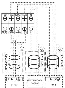
flowchart
graph TD
    subgraph_Switch_S["Switch S(1)"]
        S1["S(1)"] --> S2["S(2)"]
        S2 --> S3["S(A)"]
        S3 --> S4["N(A)"]
        S4 --> S5["L(A)"]
        S5 --> S6["N"]
        S6 --> S7["S(B)"]
        S7 --> S8["N(B)"]
        S8 --> S9["L(B)"]
        S9 --> S10["L"]
    end

    subgraph Opticones_Opticones_Opticones_Opticones_Opticones_Opticones_Opticones_Opticones_Opticones_Opticones_Opticones_Opticones_Opticones_Opticones_Opticones_Opticones_Opticones_Opticones_Opticones_Opticones_Opticones_Opticones_Opticones_Opticones_Opticones_Opticones_OPT_B
    L1["L N S⊕ TO B"]
    L2["Alimentazione elettrica"]
    L3["L N S⊕ TO A"]
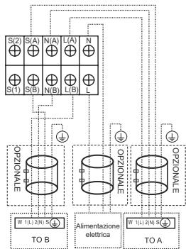
flowchart
graph TD
    subgraph Top_Layer
        S2["S(2)"] --> S1["S(1)"]
        S3["S(A)"] --> S4["S(B)"]
        S5["N(A)"] --> S6["N(B)"]
        S7["L(A)"] --> S8["L(B)"]
        S9["N"] --> S10["S(B)"]
        S11["S(1)"] --> S12["S(B)"]
        S13["S(1)"] --> S14["S(B)"]
        S15["N(A)"] --> S16["N(B)"]
        S17["L(A)"] --> S18["L(B)"]
        S19["L"] --> S20["L(B)"]
    end

    subgraph Bottom_Layer
        W1["W 1/L:2/N S"] --> TOB["TO B"]
        W2["W 1/L:2/N S"] --> TOA["TO A"]
        W3["W 1/L:2/N S"] --> TOA
        W4["W 1/L:2/N S"] --> TOA
    end

    S2 -->|OPZIONALE| W1
    S3 -->|OPZIONALE| W2
    S4 -->|OPZIONALE| W3
    S5 -->|OPZIONALE| W4
    S6 -->|OPZIONALE| W5
    S7 -->|OPZIONALE| W6
    S8 -->|OPZIONALE| W7
    S9 -->|OPZIONALE| W8
    S10 -->|OPZIONALE| W9
    S11 -->|OPZIONALE| W10
    S12 -->|OPZIONALE| W11
    S13 -->|OPZIONALE| W12
    S14 -->|OPZIONALE| W13
    S15 -->|OPZIONALE| W14
    S16 -->|OPZIONALE| W15
    S17 -->|OPZIONALE| W16
    S18 -->|OPZIONALE| W17
    S19 -->|OPZIONALE| W18
    S20 -->|OPZIONALE| W19
    W1 & W2 & W3 & W4 & W5 & W6 & W7 & W8 & W9 & W10 & W11 & W12 & W13 & W14 & W15 & W16 & W17 & W18 & W19 & W20 & W21 & W22 & W23 & W24 & W25 & W26 & W27 & W28 & W29 & W30 & W31 & W32 & W33 & W34 & W35 & W36 & W37 & W38 & W39 & W40 & W41 & W42 & W43 & W44 & W45 & W46 & W47 & W48 & W49 & W50 & W51 & W52 & W53 & W54 & W55 & W56 & W57 & W58 & W59 & W60 & W61 & W62 & W63 & W64 & W65 & W66 & W67 & W68 & W69 & W70 & W71 & W72 & W73 & W74 & W75 & W76 & W77 & W78 & W79 & W80 & W81 & W82 & W83 & W84 & W85 & W86 & W87 & W88 & W89 & W90 & W91 & W92 & W93 & W94 & W95 & W96 & W97 & W98 & W99 & X-axis label: TO B, Alimentazione elettrica, TO A, TO B, TO C, TO D, TO E, TO F, TO G, TO H, TO I, TO J, TO K, TO L, TO M, TO N, TO O, TO P, TO Q, TO R, TO S, TO T, TO U, TO V, TO V, TO A, TO A', Y-axis label: OPZIONALE, ALIMENTAZIONE ELECTRICA, TO B, TO C, TO D, TO E, TO F, TO G, TO H, TO I, TO J, TO K, TO L, TO M, TO N, TO P, TO Q, TO R, TO S, TO T, TO U, TO V, TO Z, Y-axis label: OPZIONALE, ALIMENTAZIONE ELECTRICA, TO B, TO C, TO D, TO E, TO F, TO G, TO H, TO I, TO J, TO K, TO L, TO M, TO N, TO O, TO P, TO Q, TO R, TO S, TO T, TO U, TO V, TO A, Y-axis label: OPZIONALE, ALIMENTAZIONE ELECTRICA, TO B, TO C, TO D, TO E, TO F, TO G, TO H, TO I, TO J, TO K, TO L, TO M, TO N, TO O, TO P, TO Q, TO R, TO S, TO T, TO U, TO V, TO A, Y-axis label: OPZIONALE, ALIMENTAZIONE ELTRICA, TO B, TO C, TO D, TO E, TO F, TO G, TO H, TO I, TO J, TO K, TO L, TO M, TO N, TO O, TO P, TO Q, TO R, TO S, TO T, TO U, TO V, TO A
TRIAL

flowchart
graph TD
    subgraph Power
        L1["L"] --> L2["L(A)"]
        L3["L"] --> L4["N(A)"]
        L5["S"] --> L6["A"]
        L7["L"] --> L8["B"]
        L9["N"] --> L10["S"]
        L10["S"] --> L11["B"]
        L11 --> L12["B"]
        L12 --> L13["B"]
        L13 --> L14["B"]
    end

    subgraph To Indoor Unit A
        L1a["L N"] --> L1b["L N S"]
        L1c["1(L) 2(N) S"] --> L1d["1(L) 2(N) S"]
        L1e["or"] --> L1f["W 1(L) 2(N) S"]
        L1g["or"] --> L1h["W 1(L) 2(N) S"]
        L1i["or"] --> L1j["1(L) 2(N) 3(S)"]
        L1k["or"] --> L1l["1(L) 2(N) 3(S)"]
    end

    subgraph To Indoor Unit B
        L1m["L N"] --> L1n["L N S"]
        L1o["1(L) 2(N) S"] --> L1p["1(L) 2(N) S"]
        L1q["or"] --> L1r["W 1(L) 2(N) S"]
        L1s["or"] --> L1t["W 1(L) 2(N) S"]
        L1u["or"] --> L1v["1(L) 2(N) 3(S)"]
        L1w["or"] --> L1x["1(L) 2(N) 3(S)"]
    end

    subgraph To Indoor Unit C
        L2n["L C"] --> L2nL["N(C)"]
        L2nL["N(C)"] --> L2nS["S(C)"]
        L2nS["N(C)"] --> L2nN["S(C)"]
    end

    style Power fill:#f9f,stroke:#333
    style To Indoor Unit A fill:#ccf,stroke:#333
    style To Indoor Unit B fill:#ccf,stroke:#333
    style To Indoor Unit C fill:#ccf,stroke:#333

3 - BESCHRIJVING APPARAAT 7
3.1 - MUURINSTALLATIE....7
3.2 - MINIMALE OMGEVINGSZONE IN GEVAL VAN KOELGASVULLING 8
3.3 - BEDRIJFSOMSTANDIGHEDEN 8
3.4 - WENKEN VOOR DE ENERGIEBESPARING 9
9 - LUCHT EVACUATIE....23
9.1 - INSTALLATIESCHEMA 25
9.2 - TEST RUN....25
10 - FUNCTIE VAN AUTOMATISCHE BEDRADINGS-/LEIDINGSCORRECTIE 26

VUILVERWERKING
3 - BESCHRIJVING APPARAAT
3.1 - MUURINSTALLATIE
Binnenunit
4.3 - OPTIMALE WERKING
natural_image
Line drawing of a multi-compartment air conditioner unit with fan blades (no text or symbols)natural_image
Diagram of a mechanical clamp or tool interacting with a bolt, showing rotational motion (no text or symbols)natural_image
Line drawing of a dual-gauge pressure regulator with a hook and valve (no text or symbols)natural_image
Line drawing of a handheld device with a coiled cable and bulb (no text or symbols)
• Voer een test uit
7.2 - INSTALLATIESCHEMA
..... Dual
--- Trial
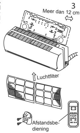
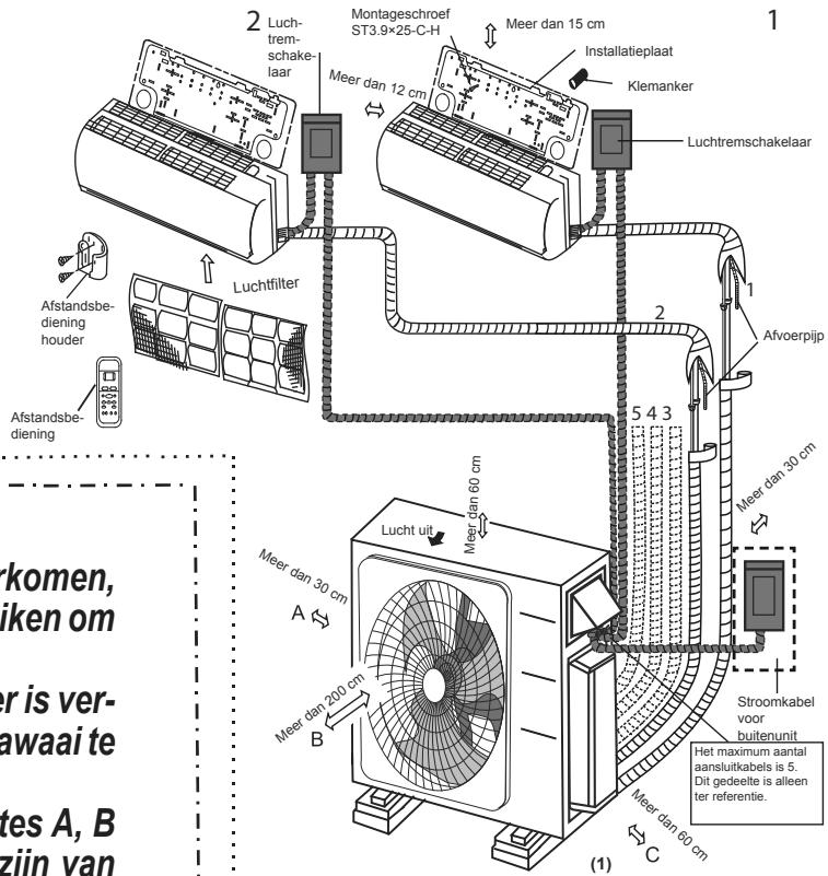
natural_image
Technical line drawing of a front-end air conditioner unit with fan and side-mounted buttons (no text or symbols)
| Afmetingen buitenunitW × H × D (mm) | Montage Afmetingen (mm) | |
| Afstand A | Afstand B | |
| 940x10x410 | 673 | 403 |
| 800x554x330 | 511 | 317 |
| 890x673x342 | 663 | 354 |

natural_image
Technical illustration of two mechanical clamping devices with no visible text or symbols
NL - 18
flowchart
graph TD
    subgraph Power
        A["POWER"] --> B["Optional Unit"]
        B --> C["Optional Unit"]
        C --> D["Optional Unit"]
    end

    subgraph To Indoor Unit A
        E["To indoor unit A"] --> F["1(L) 2(N) S"]
        G["To indoor unit B"] --> H["1(L) 2(N) S"]
        I["To indoor unit C"] --> J["1(L) 2(N) 3(S)"]
    end

    subgraph To Indoor Unit B
        K["To indoor unit B"] --> L["1(L) 2(N) 3(S)"]
        M["To indoor unit C"] --> N["1(L) 2(N) 3(S)"]
    end

    subgraph To Indoor Unit C
        O["To indoor unit C"] --> P["1(L) 2(N) 3(S)"]
    end

    style Power fill:#f9f,stroke:#333
    style To Indoor Unit A fill:#ccf,stroke:#333
    style To Indoor Unit B fill:#ccf,stroke:#333
    style To Indoor Unit C fill:#ccf,stroke:#333
    style To Indoor Unit A fill:#dfd,stroke:#333
    style To Indoor Unit B fill:#dfd,stroke:#333
    style To Indoor Unit C fill:#dfd,stroke:#333
    style To Indoor Unit C fill:#dfd,stroke:#333


- - GENERAL WARNINGS....2
- - INSTRUCTIONS FOR INSTALLATION....7
- - APPLIANCE DESCRIPTION ....7
- - OPERATIONS AND MAINTENANCE ......9
- - TROUBLESHOOTING....10
- - ACCESSORIES 12
- - INSTALLATION ...... 13
- - WIRING....21
- - AIR EVACUATION....23
- - FUNCTION OF AUTOMATIC WIRING/PIPING CORRECTION 26
- DISPOSAL
- - SYMBOLS
- Index
- HAZARD
- GENERIC DANGER
- - GENERAL WARNINGS
- WHEN USING ELECTRICAL EQUIPMENT, BASIC SAFETY PRECAUTIONS MUST ALWAYS BE FOLLOWED IN ORDER TO REDUCE RISKS OF FIRE, ELECTRIC SHOCKS AND INJURY, INCLUDING THE FOLLOWING:
- - NOTES REGARDING FLUORINATED GASES
- - PROPER USE
- - HAZARDOUS ZONES
- - FUSE SPECIFICATIONS
- - INSTRUCTIONS FOR INSTALLATION
- - APPLIANCE DESCRIPTION
- - WALL INSTALLATION
- Indoor unit
- Outdoor unit
- - RECOMMENDATIONS FOR ENERGY SAVINGS
- - OPERATIONS AND MAINTENANCE
- - OPERATION MODE SELECTION
- - MAINTENANCE
- When the air conditioner is to be used again:
- - TROUBLESHOOTING
- - SAFETY PRECAUTIONS
- IN THE PRESENCE OF THESE CONDITIONS, DO NOT TRY TO SOLVE THE ANOMALY BY YOURSELF. PROMPTLY CONTACT A RETAILER OR AN AUTHORIZED ASSISTANCE CENTRE!
- - COMMON ISSUES
- - FUNCTIONAL ASPECTS NOT TO BE MISTAKEN FOR ANOMALIES
- PROTECTION OF THE AIR CONDITIONER.
- WHITE MIST ESCAPES FROM THE INDOOR UNIT
- SLIGHT AIR CONDITIONER NOISE
- DUST IS BLOWN OUT FROM THE INDOOR UNIT.
- A STRANGE ODOUR IS DETECTED COMING FROM THE INDOOR UNIT.
- THE AIR CONDITIONER GOES TO FAN ONLY MODE FROM HEATING AND COOLING MODE
- POSSIBLE DRIPPING OF WATER.
- HEATING MODE
- AUTOMATIC RE-START FUNCTION
- LIGHTENING OR ELECTRIC EQUIPMENT
- - ACCESSORIES
- - INSTALLATION
- - PROCEDURES FOR INSTALLATION
- - INSTALLATION DIAGRAM
- - Specifications
- - OUTDOOR UNIT INSTALLATION
- - Step 1: Select installation location
- - Special considerations for extreme weather
- - Step 2: Install drain joint (Heat pump unit only)
- - Step 3: Anchor outdoor unit
- - UNIT MOUNTING DIMENSIONS
- - NOTES ON DRILLING HOLE IN WALL
- - REFRIGERANT PIPING CONNECTION
- - Step 1: Cut pipes
- DO NOT DEFORM PIPE WHILE CUTTING.
- - Step 2: Remove burrs
- - Step 3: Flare pipe ends
- - Step 4: Connect pipes
- -
- WIRING
- MAKE SURE THAT:
- - EXTERNAL UNIT WIRING
- - AIR EVACUATION
- BEFORE PERFORMING EVACUATION
- OPEN VALVE STEMS GENTLY
- - INSTALLATION DIAGRAM
- Gas leak check
- - TEST RUN
- For the Outdoor Unit
- - FUNCTION OF AUTOMATIC WIRING/PIPING CORRECTION
- To activate this function:
- ELIMINATION
- - ÉVACUATION D'AIR
- - ALLGEMEINE WARNHINWEISE....2
- SCHUTZ DES KLIMAGERÄTS.
- - PROBLEMAS E RESOLUÇÕES
- - Passo 2: Remova as saliências
- DUAL
- TRIAL
- - BESCHRIJVING APPARAAT 7
- - LUCHT EVACUATIE....23
- - FUNCTIE VAN AUTOMATISCHE BEDRADINGS-/LEIDINGSCORRECTIE 26
- VUILVERWERKING
- - BESCHRIJVING APPARAAT
- - MUURINSTALLATIE
- Binnenunit
- - OPTIMALE WERKING
- - INSTALLATIESCHEMA
Brand : OLIMPIA SPLENDID
Model : ARYAL S2 E DUAL - TRIAL
Category : Air conditioner outdoor unit