LIGHT SHOW 5FX - Laser BOOMTONEDJ - Free user manual and instructions
Find the device manual for free LIGHT SHOW 5FX BOOMTONEDJ in PDF.

| Product type | Multi-effect laser projector |
| Brand | BoomtoneDJ |
| Model | LIGHT SHOW 5FX |
| Category | Laser |
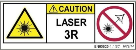
| Laser class | 3R (EN60825-1:2014) |
| Light sources | Crystal Ball: 1x 12W RGBW 4in1, Strobe/UV: 4x 10W white/UV, Laser: 120mW green + 30mW red, LED wash: 4x 6W RGBW 4in1 |
| Coverage angle | 120° |
| Operating modes | DMX (18 channels), Automatic, Sound activation, IR remote control |
| Power supply | AC 100-240 V, 50/60 Hz |
| Power consumption | 60 W max |
| Fuse | F3A/250V |
| Dimensions (unit) | 185 x 185 x 120 mm |
| Net weight | 0.8 kg |
| Dimensions (box) | 245 x 140 x 220 mm |
| Gross weight | 1.2 kg |
| Operating temperature | Max 40 °C |
| Standards | LVD 2006/95/CE, RoHS 2 2011/65/UE, EMC 2014/30/UE, EN 60825-1:2014 |
| Maintenance | Regular lens cleaning with a soft cloth and glass cleaner (unplugged device) |
| Spare parts | User-replaceable fuse; no other user-serviceable parts |
| Included accessories | Power cable with ground, IR remote control, user manual |
| Usage | Professional (show, display) - Laser out of public reach |
Frequently Asked Questions - LIGHT SHOW 5FX BOOMTONEDJ
User questions about LIGHT SHOW 5FX BOOMTONEDJ
0 question about this device. Answer the ones you know or ask your own.
Ask a new question about this device
Download the instructions for your Laser in PDF format for free! Find your manual LIGHT SHOW 5FX - BOOMTONEDJ and take your electronic device back in hand. On this page are published all the documents necessary for the use of your device. LIGHT SHOW 5FX by BOOMTONEDJ.
USER MANUAL LIGHT SHOW 5FX BOOMTONEDJ
natural_image
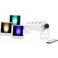
Black octagonal projector with a reflective central display and control panel, no visible text or symbols-LightShow 5FX-
text_image
CAUTION LASER 3R EN60825-1 / IEC 1072/14
text_image
LINKABLE STAND ALONE
text_image
SOUND ACTIVATED
text_image
DMX512
text_image
CE RoHS 2011/65/EUMODE D'EMPLOI – USER
MANUAL
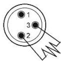
Termination reduces signal errors and to avoid signal transmission problems and interference. It is always advisable to connect a DMX terminal.
(Resistance 120 ohm 1/4W) between pin2 (DMX-) and pin3 (DMX+) of the last fixture.
2- Safety instructions

Before using your equipment, we recommend that you read all the instructions in this manual.
CAUTION:
CLASS 3R LASER DEVICE
HAZARDOUS BEAM EXPOSURE
LASER RADIATION
Visible and invisible LASER radiation. Avoid direct or indirect exposure to eyes or skin! LASER Class III R EN60825-1:2014 in accordance with the following European Directives:
Keep this manual for future reference. If you resell this device, be sure to pass on this manual to the new owner.
Completely unpack the unit and all its accessories. Check that there is no damage and that the unit is in perfect condition.
It is important to use the supplied power cable (grounded cable).
Always unplug the unit before servicing or maintenance.
Maximum ambient temperature for optimal operation of the device: 40^ C.
Do not use the unit if the ambient temperature exceeds this value.
In the event of a malfunction, switch off the unit immediately. Do not attempt to repair it yourself. Contact your dealer or an authorized specialist repairer.
There are no user replaceable parts except for the fuse.
Do not connect this unit to a dimmer pack.
To reduce the risk of fire or electric shock, do not use this product in a humid or rainy environment.
- Do not look directly at the light beam. The light from a LASER can cause permanent damage to the eyes.
This unit must be installed with a sturdy hook of adequate size for the weight carried. The unit must be screwed to the hook and tightened properly to prevent it from falling due to vibrations produced by the machine during operation. The hook must be secured with a safety sling. Also, make sure that the structure (or hanging point) can support at least 10X the weight of the suspended device.
The device must be installed by a qualified person and must be placed out of reach of the public.
Operating Premises: Whenever possible, a LASER should be operated in a room or area reserved for this purpose, enclosed or delimited.
The accesses to the premises and their openings to the outside must not be located in the axis of a direct beam.
The floor must be free of obstacles. The causes of reflection and accidental diffusion of laser beams must be eliminated (poorly placed windows, furniture or objects with polished faces).
Paintings (walls, partitions, ceilings, etc.) and floor coverings should preferably be matte. In this respect, diffuse reflections of class 4 lasers, focused beams of class 3 lasers with visible or near infrared light must be considered as dangerous and treated as such.
When using powerful lasers (class 3 focused beam or 4), the possibility of the beam impacting on flammable materials (wood, paper, fabrics or plastics) must be eliminated, which can cause fires under power densities of the order of a few W.cm-2 applied for a few seconds.
Access to laser emission areas must be marked using signs that comply with the ministerial order of November 4, 1993 "Health and safety signs in the workplace" and the standard NF X 08-003 "Graphic symbols and pictograms - colors and safety signs" of December 1994. This signage is completed by the mention of the class of the laser device and the instructions provided in standard NF EN 60825-1. These accesses can be controlled, at least when lasers are in operation.
Control of emissions: the control panel should be placed outside the areas exposed to dangerous emissions. The control of class 3 and 4 lasers must be under the dependence of a control key, removed when the device is not in use and held by a qualified person.
Warning:
This equipment is intended for use in professional entertainment and display activities only.
When in use, this equipment must be installed so that the rays remain above the eye level of the audience and do not reach them in any way.
It is forbidden to use this device for any purpose other than that for which it is intended.
The manufacturer and distributor are not responsible for any damage caused by the LASER BoomtoneDJ. The user is responsible for the use and compliance with the regulations NF EN 60825-1:2014.
2- Technical specifications
- Ultra-complete light set with 5 different effects
- Laser, Strob, Crystal Ball, UV, LED wash
- Crystal Ball: 1 LED 12W RGBW 4in1 Light Sources
- Strob and UV light sources: 4 x 10W white and UV LEDs
- Laser light sources: 120mW Green and 30mW Red
- LED wash light sources: 4 x 6W RGBW 4in1 LEDs
- 4 operating modes: DMX, Automatic, Music detection, IR remote control
- Coverage angle: 120 degrees
- DMX: 18 channels
- Power supply : AC100-240V 50/60Hz
- Fuse: F3A/250V
- Maximum power consumption : 60W
- Dimensions of the device: 185×185×120mm
- Carton size: 245 x 140 x 220 mm
- Net weight: 0.8 kg
- Gross weight : 1.2 kg
This intelligent projector complies with the current European standards: EN 2014/30/EU, EN 2011/65/EU, EN 2014/35/EU.
Selection of the operating mode
| Menu | Menu level 2 | Function |
| A001 | A001-A512 | DMX address |
| LE1 | LE11-LE19 | Crystal Ball red, 1-9 speed |
| LE2 | LE21-29 | Crystal Ball green, 1-9 speed |
| LE3 | LE31-39 | Crystal Ball blue, 1-9 speed |
| LE4 | LE41-49 | Crystal Ball white, 1-9 speed |
| LE5 | LE51-59 | Crystal ball auto mode, 1-9 speed |
| LS | LS1-LS9 | LASER mode Auto, 1-9 speed |
| Pu | Pu1-Pu9 | UV |
| By | Par1-Par9 | LED wash mode auto, 1-9 speed change |
| FL | FL1-FL9 | Strob white, 1-9 flash speed |
| Au1 | Au11-Au19 | Auto mode, 1-9 program speed |
| S1 | S11-S19 | Sound mode 1, 1-9 microphone sensitivity |
| S2 | S21-S29 | Sound mode 2, 1-9 microphone sensitivity |
A. DMX mode
This mode allows you to control your fixture with a DMX controller. Each fixture must be "addressed" from 1 to 512.
Press MENU until you see A001, press ENTER, then use the DOWN and UP keys to select the desired DMX address. Press ENTER to confirm the value. When the DMX address is flashing, it confirms that your fixture is receiving a DMX signal from your controller.
DMX protocol:
| Channel | Value | Function |
| CH1 | 0-255 | Speed of rotation of the Crystal Ball |
| CH2 | 0-255 | Position of the Crystal Ball |
| CH3 | 0-255 | LASER gobo rotation |
| CH4 | 0-255 | Dimmer |
| CH5 | 0-255 | General stroboscopic effect |
| CH6 | 0-255 | Crystal Ball red |
| CH7 | 0-255 | Green Crystal Ball |
| CH8 | 0-255 | Crystal Ball blue |
| CH9 | 0-255 | Crystal Ball white |
| CH10 | 0-255 | Red LASER |
| CH11 | 0-255 | Green LASER |
| CH12 | 0-255 | Red LED |
| CH13 | 0-255 | Green LED |
| CH14 | 0-255 | Blue LED |
| CH15 | 0-255 | White LED |
| CH16 | 0-255 | UV |
| CH17 | 0-255 | White strob from slow to fast |
| CH18 | 0-50 | N/A |
| 51-150 | Auto mode | |
| 151-255 | Sound mode |
B. Use with IR remote control :
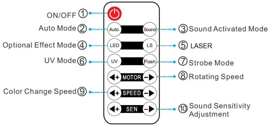
flowchart
graph TD
    A["ON/OFF ①"] --> B["Power Symbol"]
    C["Auto Mode ②"] --> D["Auto"]
    E["Optional Effect Mode ④"] --> F["LED"]
    G["UV Mode ⑥"] --> H["UV"]
    I["Color Change Speed ⑨"] --> J["MOTOR"]
    K["SEEN"] --> L["SPEED"]
    M["Sound Sensitivity Adjustment"] --> N["+"]
    O["Sound Activated Mode"] --> P["●"]
    Q["LASER"] --> R["●"]
    S["Strobe Mode"] --> T["●"]
    U["Rotating Speed"] --> V["●"]
    W["Sound Sensitivity Adjustment"] --> X["●"]
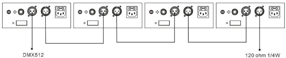
4. DMX mode (DMX connection)
text_image
DMX512 120 ohm 1/4W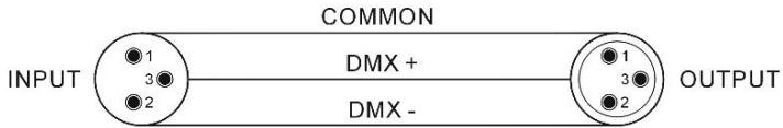
text_image
COMMON INPUT DMX + DMX - OUTPUTTermination reduces signal errors and to avoid signal transmission problems and interference. It is always advisable to connect a DMX terminal.
(Resistance 120 ohm 1/4W) between pin2 (DMX-) and pin3 (DMX+) of the last fixture.

- If you are using a controller with a 5-pin XLR DMX output, you need to get an XLR 5-pin/3-pin adapter.
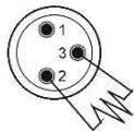
- On the last device of the DMX chain, it is recommended to use a "DMX plug". (a 120 Ohms 1/4W resistor between pin 2 (DMX-) and pin 3 (DMX+) placed in a male DMX connector).
- Connect the fixtures one after the other: DMX output to DMX input of the next fixture. The DMX cable should NEVER be a "Y" cable. The DMX-512 link carries a high speed signal. The cables used for this link must be of good quality and in good condition.
- Each fixture must have a specific DMX address in order to be controlled by the DMX controller. (see table above).
5- Troubleshooting
Here are some suggestions if you are having problems with your device.
• The device does not work at all.
- Check the power cord and fuse.
○ Make sure your outlet is well powered.
- The fixture does not respond or does not respond correctly to DMX commands.
○ Check your DMX cables
○ Check your DMX addressing
- Try another DMX controller
○ Make sure that your DMX cables do not run close to high-voltage cables, which could cause interference.
• Does not respond to sound
- Check the selected operating mode
○ Make sure there is no DMX cable connected to DMX IN - Tap directly on the microphone to test its responsiveness.
6 - Maintenance
The exterior of the unit should be cleaned regularly. The lenses must be cleaned for optimum brightness. If the unit is installed in a dusty or smoky environment this regular maintenance is very important. It may be necessary to clean the optics from the inside as well. Unplug the unit before servicing!
- Use a clean cloth with very little glass cleaner. Always dry the cleaned parts well.
Termination reduces signal errors and to avoid signal transmission problems and interference. It is always advisable to connect a DMX terminal. (Resistance 120 ohm 1/4W) between pin2 (DMX-) and pin3 (DMX+) of the last fixture.

Termination reduces signal errors and to avoid signal transmission problems and interference. It is always advisable to connect a DMX terminal. (Resistance 120 ohm 1/4W) between pin2 (DMX-) and pin3 (DMX+) of the last fixture.
KLASSE 3R LASERAPPARAAT
BLOOTSTELLING AAN GEVAARLIJKE STRALEN
LASERSTRALING