CROSSAIR-MAG C2 - Exercise bike CARE FITNESS - Free user manual and instructions
Find the device manual for free CROSSAIR-MAG C2 CARE FITNESS in PDF.
User questions about CROSSAIR-MAG C2 CARE FITNESS
0 question about this device. Answer the ones you know or ask your own.
Ask a new question about this device
Download the instructions for your Exercise bike in PDF format for free! Find your manual CROSSAIR-MAG C2 - CARE FITNESS and take your electronic device back in hand. On this page are published all the documents necessary for the use of your device. CROSSAIR-MAG C2 by CARE FITNESS.
USER MANUAL CROSSAIR-MAG C2 CARE FITNESS
Important: Read these instructions before using the equipment!
Safety
- Read this user manual and keep it in a safe place. Use this product exclusively in the manner indicated.
- This equipment must be assembled and used by adults.
- The equipment complies with the EN-957 standard, classification H for use in the home. It must not be used in a sports center or any other public, associative or rented space.
- For totally safe use, a stable, level surface is required. Protect your floor covering with a mat. Do not use the equipment in damp areas (swimming pool, sauna, etc.).
- Do not allow children to play with this equipment. CARE declines all responsibility for any injuries they may incur. Do not allow children close to this equipment when you are training.
- CARE declines all responsibility if technical modifications are made to any of its products by the user.
Maximum weight of user: 150 kg. - Before you start training, it is essential that you consult your doctor to determine the intensity level of the program you use.
- \n\n Excessive or badly programmed training can damage your health.
- Keep your back straight when exercising.
- For adjustable parts, bear the maximum positions in mind.
Maintenance
- Regularly check that elements fastened with nuts and bolts are correctly tightened.
- To maintain the level of safety, the equipment must be regularly checked. It is vital that any faulty parts are replaced and that it is not used until completely repaired. Remember regularly to grease moving parts.
- As sweat is very corrosive, do not allow it to come into contact with the enameled or chromed parts of the equipment, particularly the computer. Immediately wipe the equipment after training. The enameled parts can be cleaned using a damp sponge. All aggressive or corrosive products should be avoided.
Guarantee: the chassis is guaranteed for 5 years. Moving parts are guaranteed for 2 years. The guarantee applies to normal use by a private individual in his home. Validate your product warranty on line www.carefitness.com
Recycling : The « crossed out dustbin » sign means that this product and its batteries cannot be thrown out whit domestic waste. They should be treated apart. When you have finished with them, drop them at an authorised collection point so they can be recycled. This gesture will go towards protecting the environment and your health.
D
-
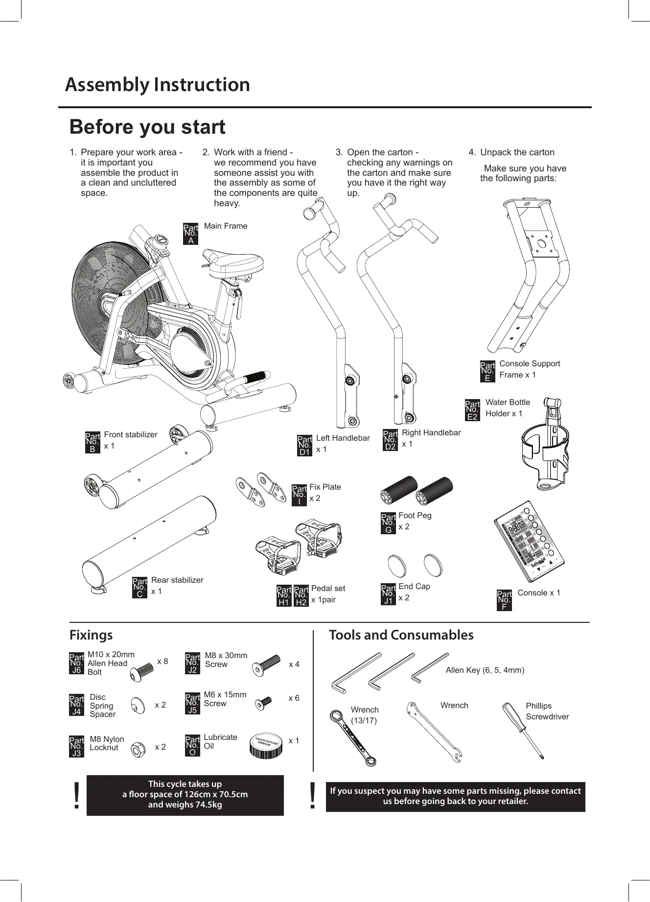
Prepare your work area - it is important you assemble the product in a clean and uncluttered space.
-
Work with a friend - we recommend you have someone assist you with the assembly as some of the components are quite heavy.
-
Open the carton - checking any warnings on the carton and make sure you have it the right way up.
-
Unpack the carton
Make sure you have the following parts:

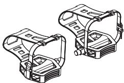
Console Support
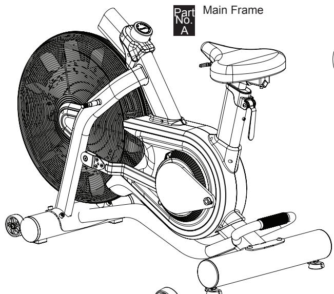
Frame x 1

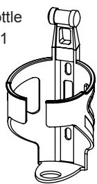
Water Bottle
Holder x 1

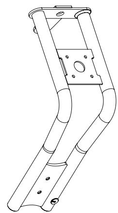
Front stabilizer

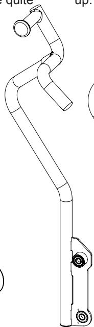
Left Handlebar

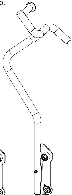
Right Handlebar
X1
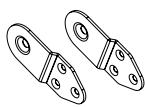

Fix Plate
X2

Part
HC H2
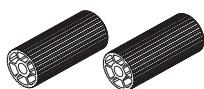
Pedal set
X

Foot Peg
X2


End Cap
X2
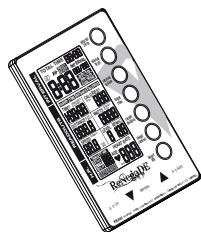

Console x 1
Fixings

M10 x 20mm
Allen Head
Bolt

X8

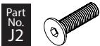
M8×30mm
Screw

X4

Disc
Spring
Spacer

X2

M6 x 15mm
Screw

x6

M8 Nylon
Locknut

X2

Lubricate
Oil

X1

This cycle takes up
a floor space of 126cm x 70.5cm
and weighs 74.5kg
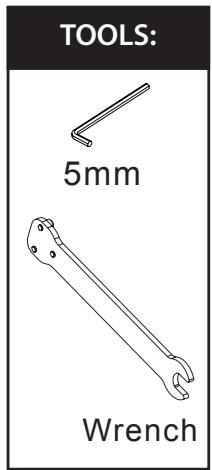
Tools and Consumables
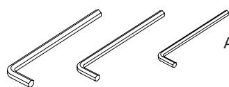
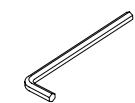
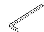
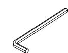
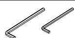
Allen Key (6, 5, 4mm)
Wrench (12/17)
Wrench

If you suspect you may have some parts missing, please contact
us before going back to your retailer.
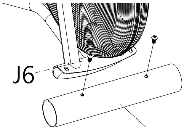
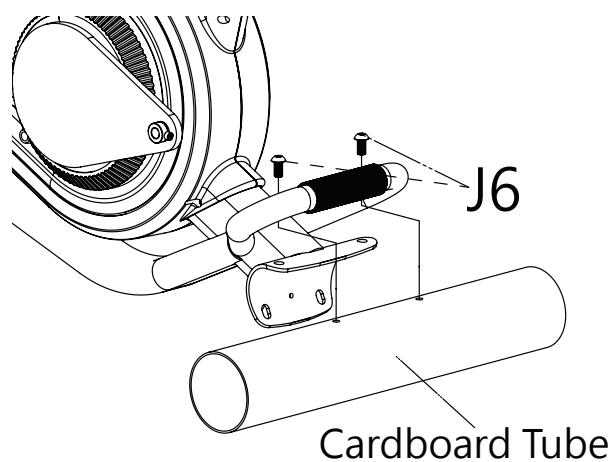
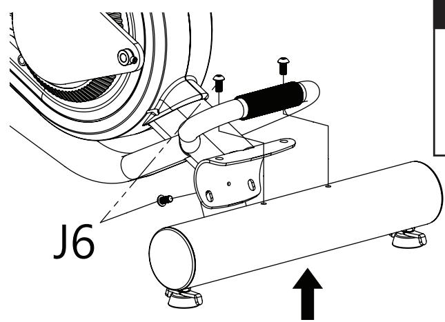
- Attach the Front Stabilizer
1-1. Remove the cardboard tube from the front end stabilizer bracket
- Loosen the two M10 x 20mm Allen Head Bolt (J6) from the cardboard tube and remove the cardboard tube.
- The cardboard tube is used for packaging protection purposes, which won't be used again during the assembly.
Cardboard Tube
FIXINGS:


X2
TOOLS:
6mm
1-2. Attach the Front Stabilizer
- Attach the Front Stabilizer (B) to the Main Frame (A) with four M10 x 20mm Allen Head Bolt (J6) and tighten these bolts with the 6mm Allen Key.
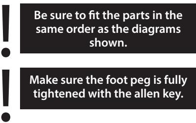
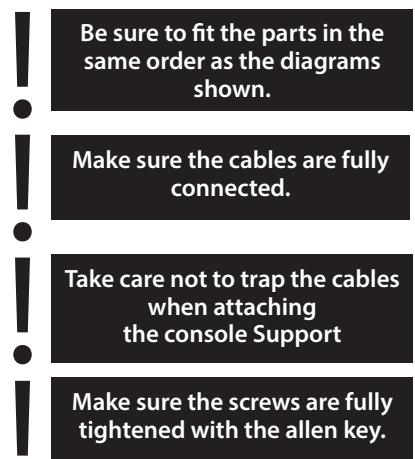
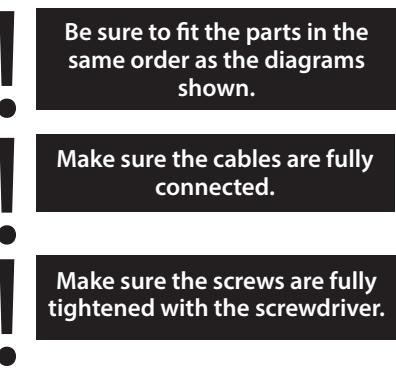
Be sure to fit the parts in the same order as the diagrams shown.
Make sure the bolts are fully tightened with the allen key.
Make sure the moving wheels on the front stabiliser face out after assembly.
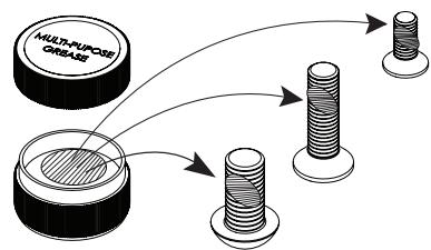
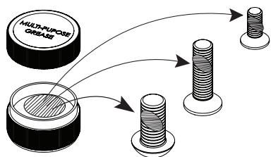
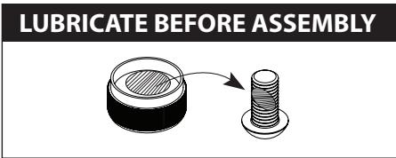
LUBRICATE BEFORE ASSEMBLY
Please lubricate the fastenings before assembly by applying some of the "multi-purpose grease" to each bolt shaft.

FIXINGS:


X4
TOOLS:
6mm
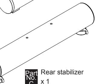
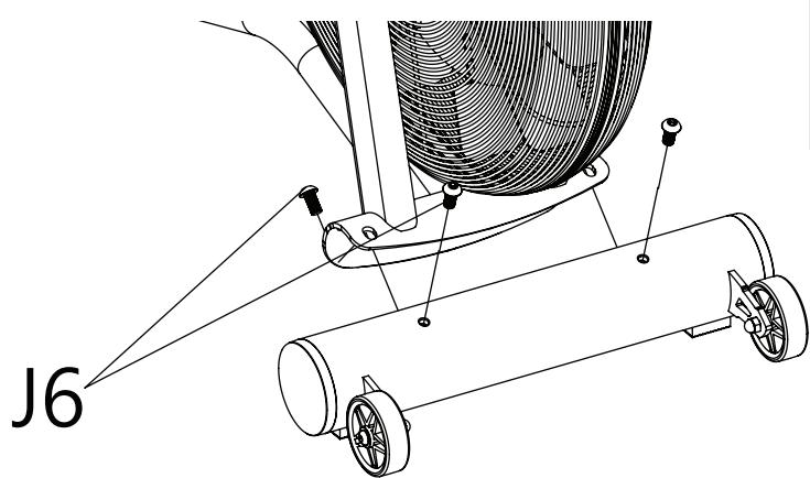
2. Attach the Rear Stabilizer
2-1. Remove the cardboard tube from the rear end stabilizer bracket
- Loosen the two M10 x 20mm Allen Head Bolt (J6) from the cardboard tube and remove the cardboard tube.
- The cardboard tube is used for packaging protection purposes, which won't be used again during the assembly.
FIXINGS:


X2
TOOLS:
6mm
2-2. Attach the Rear Stabilizer
- Attach the Rear Stabilizer (C) to the Main Frame (A) with four M10 x 20mm Allen Head Bolt (J6) and tighten these bolts with the 6mm Allen Key..
FIXINGS:


X4
Be sure to fit the parts in the same order as the diagrams shown.
Make sure the bolts are fully tightened with the allen key.
LUBRICATE BEFORE ASSEMBLY
Please lubricate the fastenings before assembly by applying some of the "multi-purpose grease" to each bolt shaft.
TOOLS:
6mm
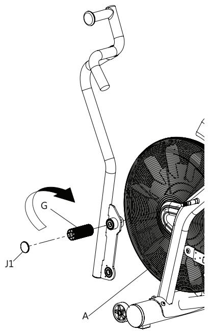
3. Attach the Dual Action Handlebars
3-1. Attach the Left Dual Action Handlebar
- Slide the left Dual Action Handlebar (D1) onto the pivot axle carefully.
Install the Foot Peg (G) by screwing it on, and tighten it with the wrench as shown. - Attach the End Cap (J1) onto the Foot Peg (G) securely.

TOOLS:
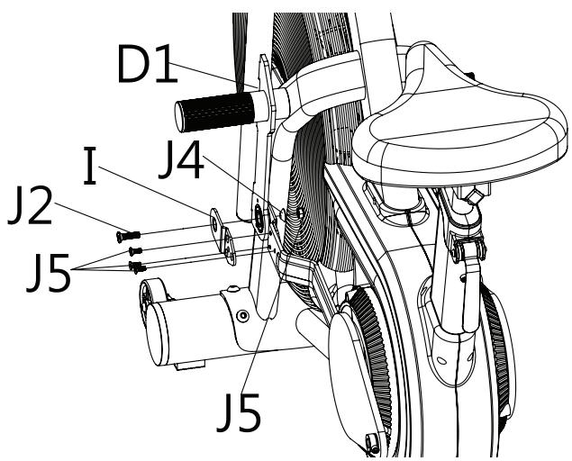
3-2. Install the Fix Plate & Linkage Bar
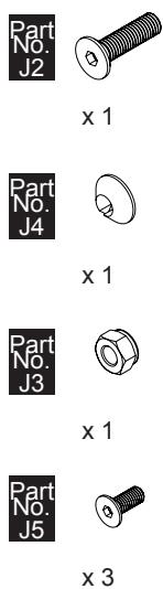
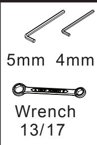
- Connect the left Dual Action Handlebar (D1) and Linkage Bar with Fix Plate (I), Disc Space r (J4), M8x30mm Screw (J2) and M8 Nylon Locknut (J3) and tighten with 5mm Allen Key & 13/17 Wrench.
- Doubly secure the Fix Plate (I) to the Linkage Bar with three M6x15mm Screws (J5) and secure with 4mm Allen Key.
( You should be able to fit these three screws for better
alignment by loosening the front screw assembly and try again when all four screws are in place, tighten with the allen key provided.
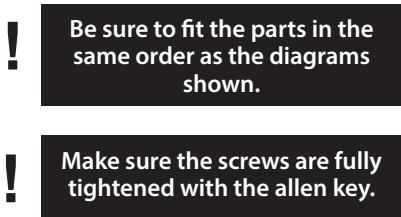
LUBRICATE BEFORE ASSEMBLY
Please lubricate the fastenings before assembly by applying some of the "multi-purpose grease" to each bolt shaft.
FIXINGS:
TOOLS:
3-3. Attach the Right Dual Action Handlebar
- Slide the right Dual Action Handlebar (D2) onto the pivot axle carefully.
Install the Foot Peg (G) by screwing it on, and tighten it with the wrench as shown. - Attach the End Cap (J1) onto the Foot Peg (G) securely.
Be sure to fit the parts in the same order as the diagrams shown.
Make sure the foot peg is fully tightened with the allen key.
Make sure the T-Knob is in un-lock position.
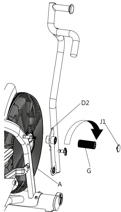
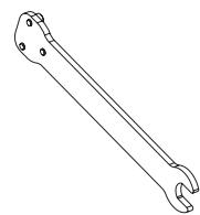
TOOLS:
Wrench
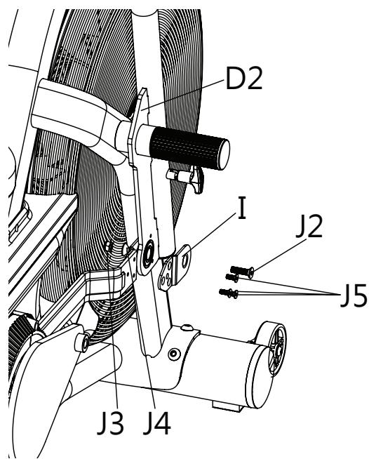
3-4. Install the Fix Plate & Linkage Bar
- Connect the right Dual Action Handlebar (D2) and Linkage Bar with Fix Plate (I), Disc Spacer (J4), M8x30mm Screw (J2) and M8 Nylon Locknut (J3) and tighten with 5mm Allen Key & 13/17 Wrench.
- Doubly secure the Fix Plate (I) to the Linkage Bar with three M6x15mm Screws (J5) and secure with 4mm Allen Key.
(You should be able to fit these three screws for better alignment by loosening the front screw assembly and try again when all four screws are in place, tighten with the allen key provided.)
Be sure to fit the parts in the same order as the diagrams shown.
Make sure the screws are fully tightened with the allen key.
LUBRICATE BEFORE ASSEMBLY
Please lubricate the fastenings before assembly by applying some of the "multi-purpose grease" to each bolt shaft.
FIXINGS:
X1

X1

x1

X3
TOOLS:
5mm 4mm
Wrench
13/17
4. Attach the Pedals
4-1. Attach the Left Pedal
- Loosen the Phillip Head Screw (J7) fitted on the left Crank Arm.
- Attach the Left Pedal (H1) to the left Crank Arm and fasten with the Wrench #14 / #15.
- Fasten the Phillip Head Screw (J7) to the Crank Arm with the 5mm Allen Key.


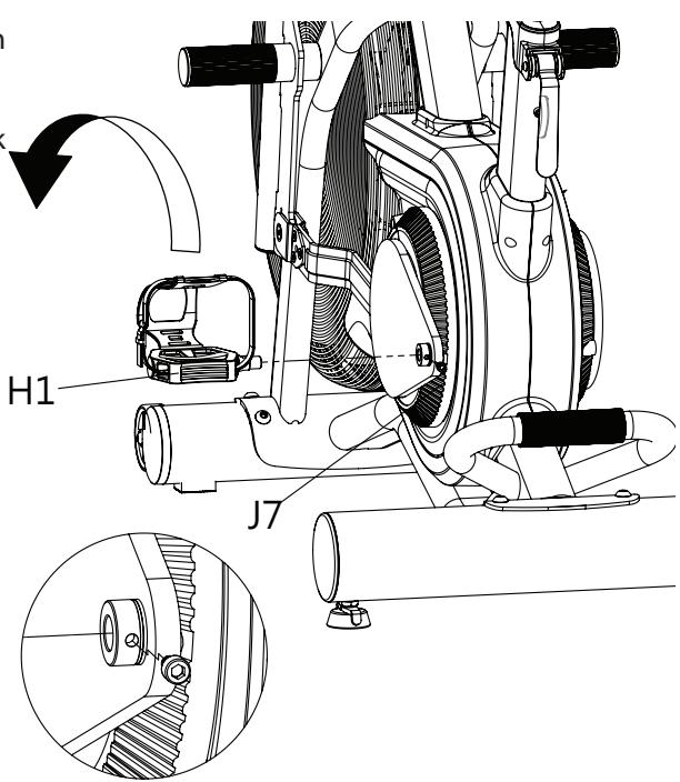

TOOLS:
5mm
Wrench
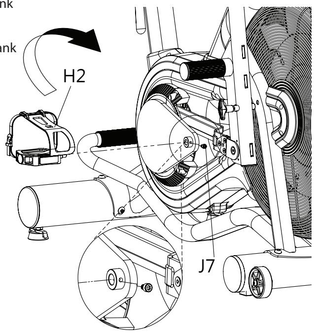
4-2. Attach the Right Pedal
- Loosen the Phillip Head Screw (J7) fitted on the right Crank Arm.
- Attach the Right Pedal (H2) to the right Crank Arm and fasten with the Wrench #14 / #15.
- Fasten the Phillip Head Screw (J7) to the Crank Arm with the 5mm Allen Key.


5. Attach the Console Support
- Attach the Console Support (E) to the front end of the Main Frame (A) with two M8x 30mm Screws (J2) and secure with the 5mm Allen Key.
- Connect the Sensor Cable and Middle Wire together.
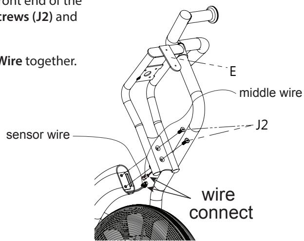
FIXINGS:


X2
TOOLS:

5mm
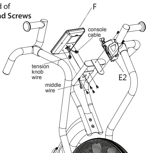
6. Attach the Console
- Remove the four fixing screws which are located in the back of the Console(8).
- Connect the Console Cable and Middle Wire together and then attach the Console (F) to the Console Support (E) with four M5 x 12mm fixing screws(F1) and secure with the Screwdriver.
- Attach the Bottle Holder (E2) to the front end of the Console Support (E) with two Phillip Head Screws - provided and scure with the 4mm Allen key.
FIXINGS:


x4

X2
TOOLS:

Phillips
Screwdriver
4mm
Final Checks
Your cycle is now assembled. Please make the following final checks before you use it for the first time
- Make sure all screws, bolts and nuts are tightened securely
- Make sure you have positioned it on a flat, level surface
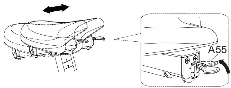
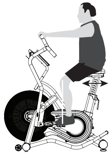
Adjusting the seat reach
- Pull up the Adjustment Grip (A55) and adjust the reach of the Saddle.
- Release the Adjustment Grip (A55) after the proper saddle position had found.
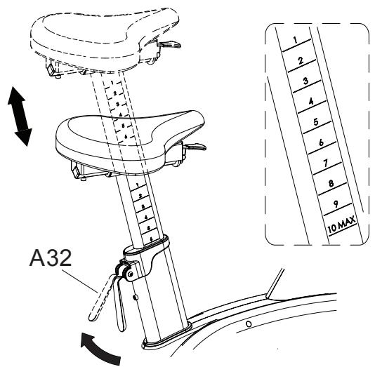
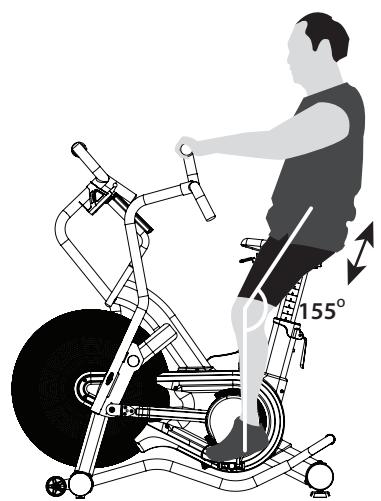
Adjusting the seat height
- Pull up the Cam Handle (A32) and adjust the height of the Saddle Post.
- Press down the Cam Handle (A32) securely after you have found the correct seat height.
Do not pull the seat post out too far - the maximum is indicated on the seat post.
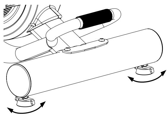
Levelling your Bike
- To help you level the Bike on uneven surface, 2 height adjusters are included on the rear stabilisers. Simply turn it to adjust the height of the Bike.
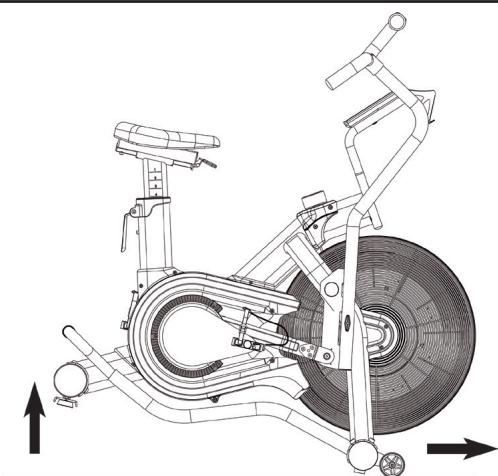
Transporting your Bike
- Your Bike has 2 transport wheels on the front stabilizer.
- Lift the Bike using the handle at the rear end of the Bike and then pull or push to move it around.
DO NOT USE THE CONSOLE SECTION TO TIP AND TRANSPORT THE BIKE
UN-LOCK - the dual arm while bike in use
- Pull & twist the T knob.
- Make sure the T knob is located parallel with the dual arm.
- Release the T knob in un-locked position as shown.
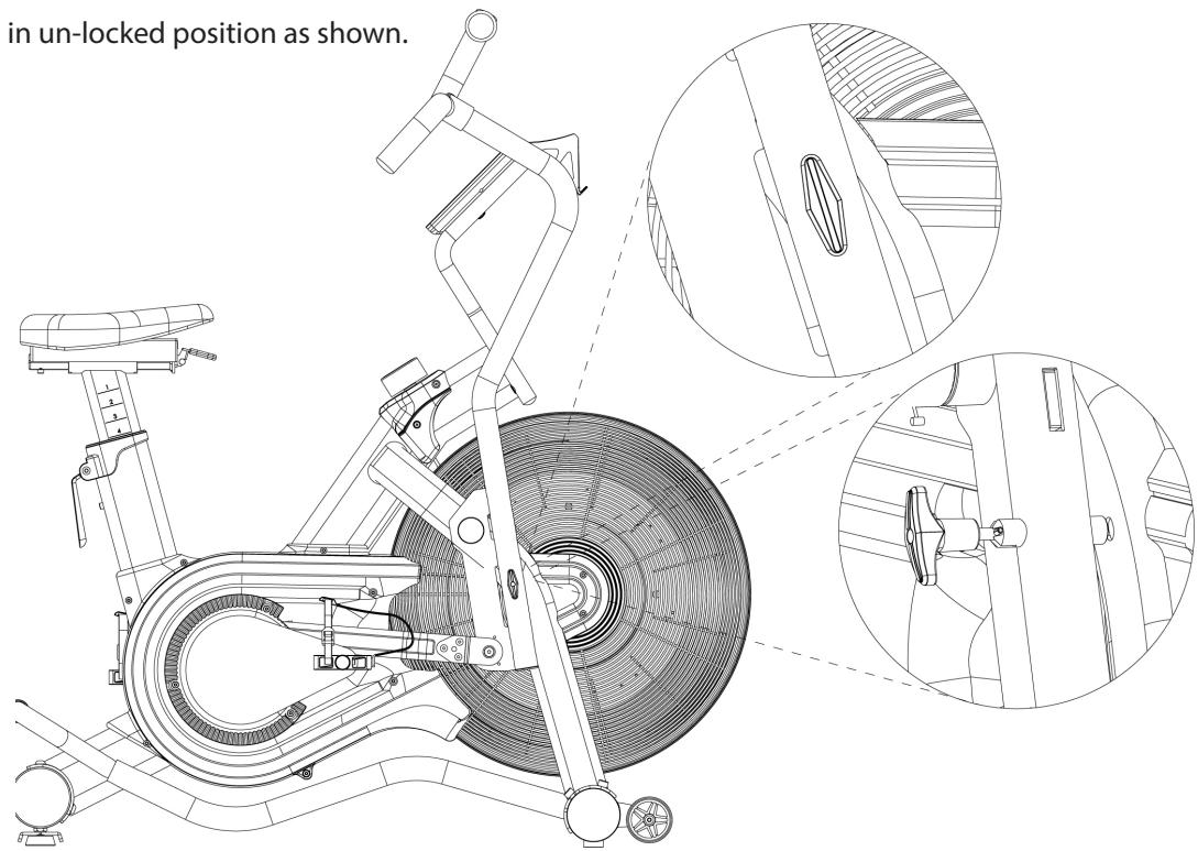
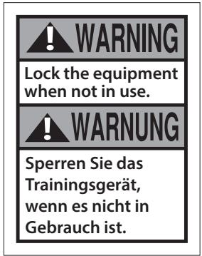
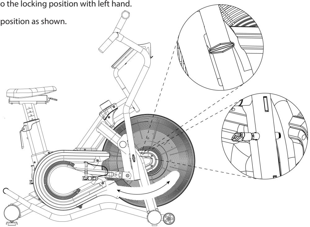
LOCK - the dual arm while bike not in use
- Pull & twist the T knob vertically to the dual arm with right hand.
- Guide the dual arm carefully to the locking position with left hand.
- Release the T knob in locking position as shown.
Adjusting the Resistance
- This Bike features a speed independent (8 levels adjustable) system.
- The harder you pedalling, the more resistance you will feel. As you put more effort into your cycling, you will go faster, produce more watts, and burn more calories. But it is more important to cycling for a longer time than to cycling harder.
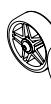
- The resistance is controlled by a magnet assembly, which is moved closer or further away from the fan wheel assembly – the closer the magnet is to the fan wheel the harder the resistance.
- The magnet is controlled manually, by twisting the dial knob.
- The resistance levels goes from 1 = easy to 8 = hard.
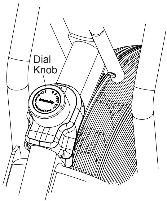
Table of Watts V.S. RPM with Level 1 ~ Level 8
| RPM | L1 | L2 | L3 | L4 | L5 | L6 | L7 | L8 |
| 10 | 2 | 2 | 2 | 3 | 3 | 4 | 6 | 10 |
| 20 | 8 | 9 | 11 | 14 | 19 | 21 | 27 | 34 |
| 30 | 22 | 23 | 27 | 35 | 44 | 55 | 68 | 81 |
| 40 | 47 | 48 | 56 | 69 | 78 | 98 | 120 | 146 |
| 50 | 85 | 88 | 98 | 117 | 136 | 160 | 188 | 222 |
| 60 | 141 | 146 | 159 | 176 | 211 | 243 | 278 | 319 |
| 70 | 223 | 228 | 246 | 278 | 310 | 347 | 388 | 434 |
| 80 | 330 | 335 | 337 | 357 | 396 | 439 | 518 | 568 |
| 90 | 471 | 485 | 510 | 540 | 594 | 653 | 740 | 810 |
| 100 | 650 | 670 | 715 | 757 | 835 | 918 | 1050 | 1117 |
| 110 | 865 | 890 | 915 | 960 | 1057 | 1163 | 1337 | 1485 |
| 120 | 944 | 1040 | 1143 | 1257 | 1383 | 1520 | 1675 | 1841 |
Note: The data may vary from the different magnetic structures / models
Quick Start
Use this mode if you just want a quick workout session and are not interested in setting up any personal data.
- Pedal for a few seconds to power the console on.
- Press the "START" button.
- The values of WATTS, SPEED, RPM, HEART RATE (if heart rate signal is detected) will start displaying.
- The values of TIME, DISTANCE, CALORIES, WATTS will start counting upwards.
To finish this quick workout session and view your workout summary –
- Stop pedaling.
- Press the "STOP" button.
The values of TIME, DISTANCE, CALORIES, WATTS, SPEED, RPM, HEART RATE
(if heart rate signal is detected) will be displayed.
"If you stop pedalling wit the program by pedalling again. After 3 minutes of inactivity the program will end."
Button Functions
INTERVAL
interval 20-10

READOUTS
"Interval" and "Target" Program buttons
- Immediately take you to the corresponding workout selected.
STOP
- To finish or pause a workout. Press and hold to reset the computer.

- To decrease values. Press and hold for rapid value change.
ENTER
- To confirm the settings.

- To increase values. Press and hold for rapid value change.
START
- To begin a workout or restart a paused program
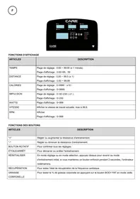
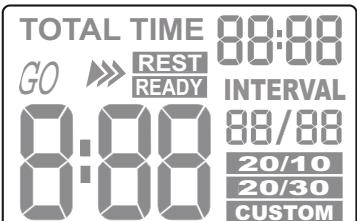
Console Display and Feedback
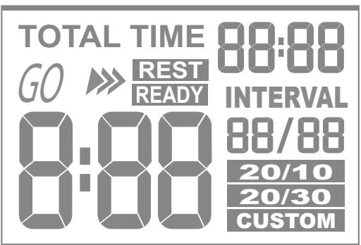
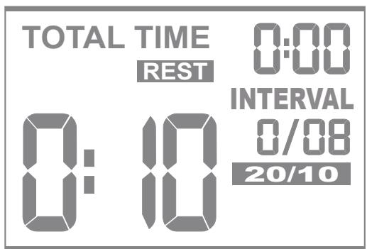
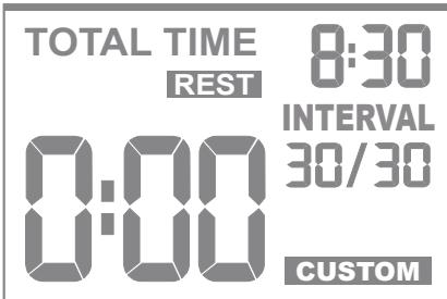
INTERVAL
- Indicates the current section is in GO period or REST period of the interval program.
- 8:88 > Shows the count down GO or REST segment time.
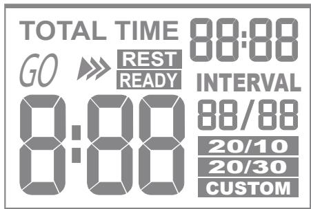
- TOTAL TIME 88:88 > Shows the count up GO & REST total run time of the program.
-
88/88 > Shows the current interval and the total sections of intervals in the program.
-
Indicates the INTERVAL 20/10 or INTERVAL 20/30 or INTERVAL CUSTOM program is selected and in used.
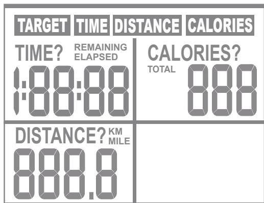
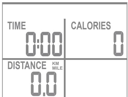
READOUTS
- Indicates the TARGET TIME or TARGET DISTANCE or TARGET CALORIES program is selected and in used.
- Indicates the time exercised this session, default counts up from zero to 1:59:00, but counts down if a target had been set.
- Indicates the distance travelled this session, default counts up from zero to 999.9 kilometers, but counts down if a target had been set.
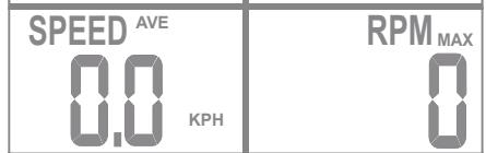
- Indicates the current speed you are pedalling at, in km/h.
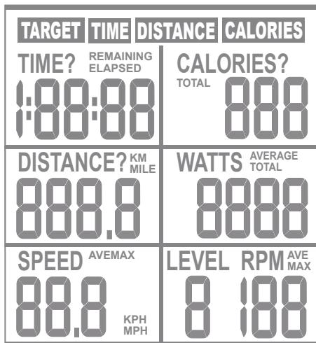
- Indicates the approximate calories burned this session (for comparison only, not to be used for medical purpose), default counts up from zero to 999 kcal, but counts down if a target had been set.
- Indicates the current energy (power) generated this session, (for comparison only, not to be used for medical purpose) default counts up from zero to 9999.
-
Indicates the current Revolutions Per Minute you are pedalling at.
-
Indicates the resistance level loaded this session, 1 = easy and 8 = hard.
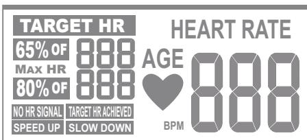
H.R.
- Indicates the current heart rate in beats per minute (bpm), which are detected by a wireless heart rate chest belt.
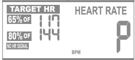
- Indicates the target to exercise at 65% of your maximum heart rate.
- Indicates the target to exercise at 80% of your maximum heart rate.
- Indicates there is no heart rate signal detected in this program.
- Indicates the current heart rate is in the target range.
-
Indicates the heart rate signal has been detected.
-
Indicates an increased pedaling speed is needed to bring the heart rate into the target range.
- Indicates an decreased pedaling speed is needed to lower the heart rate into the target range.
Using Workflow Programs
INTERVAL Programs
This console features 3 interval programs: interval 20/10, interval 20/30 & interval custom.
The interval 20/10 and interval 20/30 programs offer users a series of eight high-intensity workout intervals with preset timesegments.
These High Intensity Interval Training (H.I.I.T.) programs will automatically indicate the start of each GO & REST interval.
When you reach the last "REST" segment the console will sound a short alarm and end the workout by coming to a stop.
Interval 20/10 Program
- Make sure the console is switched on.
- Press the "interval 20/10" to select the program mode you want.
- The default interval number of "0/08" is displayed in the "INTERVAL" window.
- The default time segment of "REST 0: 10" is displayed in the "INTERVAL" window.
- Press "ENTER" to confirm your setting.
- Press "START" to begin the workout and then start pedalling. The program will not start until you begin pedalling.
NOTE: You can press the "STOP" button to end the program at any time. The workout summary will displayed on the screen.
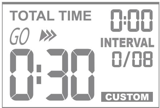
Interval 20/30 Program
- Make sure the console is switched on.
- Press the "interval 20/30" to select the program mode you want.
- The default interval number of " 0 /08 " is displayed in the " INTERVAL "window.
- The default time segment of "REST 0: 30" is displayed in the "INTERVAL" window.
- Press "ENTER" to confirm your setting.
- Press "START" to begin the workout and then start pedalling. The program will not start until you begin pedalling.
NOTE: You can press the "STOP" button to end the program at any time. The workout summary will displayed on the screen.
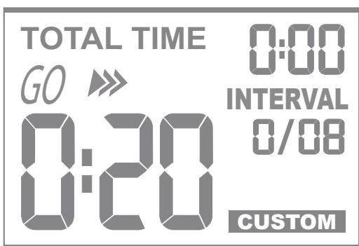
Interval custom Program
- Make sure the console is switched on.
- Press the "interval custom" to select the program mode you want.
- Use the “▼/▲” buttons to set your GO segment time (0:01 ~ 9:59 minutes)
- Press "ENTER" to confirm your setting.
- Use the"▼/▲“ buttons to set your REST segment time (0:01 ~ 9:59 minutes)
- Press "ENTER" to confirm your setting.
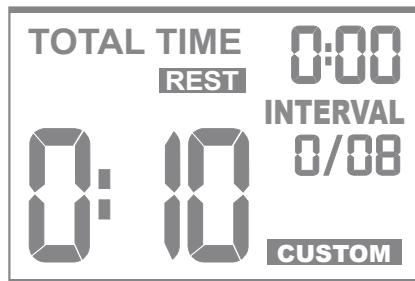
- Use the “ / ” buttons to set your total interval numbers (1~99)
- Press "ENTER" to confirm your setting.
- Press "START" to begin the workout and then start pedalling. The program will not start until you begin pedalling.
NOTE: You can press the “STOP” button to end the program at any time. The workout summary will displayed on the screen.
NOTE: You can press the “ENTER” button twice to save the setting of this program after you complete the workout.
TARGET Programs
This console features 4 target programs : Target Time, Target Distance, Target Calories & Target Heart Rate. When you reach your target the console will sound a short alarm and end the workout by coming to a stop.
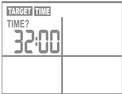
Target TIME
- Make sure the console is switched on.
- Press the "target time" to select the program mode you want.
- Use the "▼ / ▲ " buttons to set your workout time (1:00 ~ 1:59:00 minutes)
- Press "ENTER" to confirm your setting.
- Press "START" to begin the workout and then start pedalling. The program will not start until you begin pedalling.
NOTE: You can press the "t" button to end the program at any time. The workout summary will displayed on the screen.
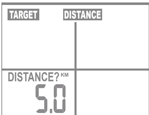
Target DISTANCE
- Make sure the console is switched on.
- Press the "target distance" to select the program mode you want.
- Use the "▼ / ▲" buttons to set your target distance (0.1 ~ 999.9km)
- Press "ENTER" to confirm your setting.
- Press "START" to begin the workout and then start pedalling. The program will not start until you begin pedalling.
NOTE: You can press the "STOP" button to end the program at any time. The workout summary will displayed on the screen.
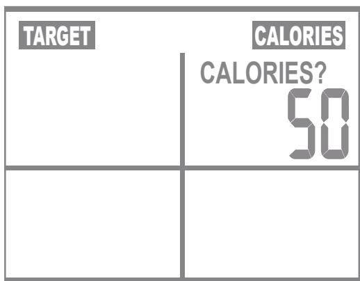
Target CALORIES
- Make sure the console is switched on.
- Press the "target calories" to select the program mode you want.
- The default value of "50" is flashing in the "CALORIES" window.
- Use the "▼ / ▲" buttons to set your target calories (10 ~ 990 kcal)
- Press "ENTER" to confirm your setting.
- Press "START" to begin the workout and then start pedalling. The program will not start until you begin pedalling.
NOTE: You can press the "STOP" button to end the program at any time. The workout summary will displayed on the screen.
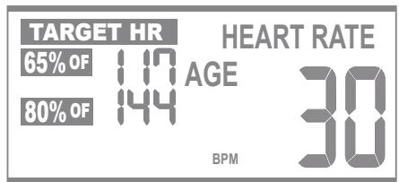
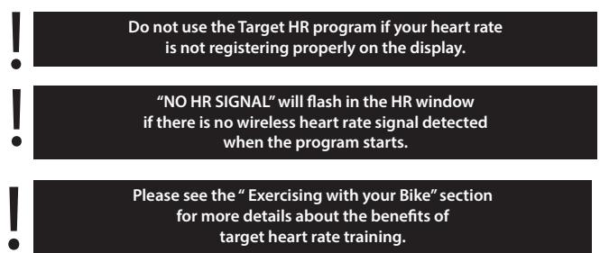
Target HR Program
You need to be wearing a compatible wireless heart rate chest belt to use this program.
Once you have entered your age the computer will calculate and display the corresponding values for 65 % and 80 % of your maximum heart rate, whilst also displaying your current heart rate. The computer will also prompt you to speed up or slow down to get within the 65 % to 80 % zone.
- Make sure the console is switched on.
- Press the "target HR" to select the program mode you want.
- The default value of "30" is flashing in the "AGE" window.
4.Use the"▼/▲"buttons to input your age (10 99) - Press "ENTER" to confirm your setting.
- The default value of the 65% of Target HR & 80% Target HR is displayed in HR window accordingly
- Press "START" to begin the workout and then start pedalling. The program will not start until you begin pedalling.
NOTE: You can press the "STOP" button to end the program at any time. The workout summary will displayed on the screen.
To order spare parts
To guarantee an efficient service, make sure you have the following items before you contact our After Sales Service:
The name or reference of the product.
The manufacturing number shown on the main chassis and on the packing box.
The number of the missing or faulty part shown on the exploded view of the product described in this manual.
Contact us from Monday to Friday between 9h00 and 12h00 and 13h00 and 17h00 (except for public holidays).
C.A.R.E.
After Sales Service
Email: sav@carefitness.com
Storage
Keep the equipment in a dry place with as little temperature variation as possible. Try to protect from dust and always unplug when not in use (if applicable).
The safety level given by the design of this air bike can only be maintained when this air bike is regularly examined for damage and wear. Inoperable components should be replaced immediately or this air bike should be put out of use until it is repaired
Never remove the protective casing.
Your air bike is designed for indoor exercising used only and should not be used or stored in damp areas.
Ensure you regularly check components for wear and make sure all the nuts & bolts are tightened before each exercise session
Maintenance Tips
Always use a soft, cotton cloth and dilute non-abrasive cleaner or a mid detergent for cleaning the exterior of this bike.
- Never use ammonia, acid-based, or petroleum-based solvents on any portion of the bike as it may damage the finish.
Preventative maintenance Schedule
Daily -
- Before each use, make certain that the area around the bike is free of obstacles that may interfere with the dual action handlebar & pedal rotation.
- Before each use, check that pedals & shaft screws are securely tightened and inspect both pedals & pedal straps for wear.
After each use, wipe down the surface of the air bike to remove sweat and moisture. - Wipe the face of the display console with a slightly damp, soft, cotton cloth. Avoid getting extra moisture on the display console. Keeping the display console free of fingerprints and sweat will extend the life of the console.
Weekly -
- Thoroughly clean the plastic housing of the bike.
- Clean the top of the pedal straps, saddle & seat post, and the display console.
- Check that pedals are securely tightened and inspect both pedals and pedal straps for wear.
- Inspect all assembly bolts & nuts for wear and ensure that they are sufficiently tight.
Monthly -
- Make sure all of the open ends of metal parts are wiped with thin grease to protect from rust.
- Check the ribbed belt is correct tension: replace cracked, frayed, or otherwise non-uniform belt. If necessary, call your local authorized distributor for Customer Service replacement.
- Inspect for side-to-side play in axle assembly, and a grinding feeling in crank area when pedaling. If necessary, call your local authorized distributor for Customer Service replacement.
- Check and Replace the Console AA Battery if needed.
- Clean for dust on Fan Wheel Assembly by spray gun if available.
We do not recommend you attempt to service the internal parts of the pedal assembly. If they are found to be worn internally, we recommend replacing the pedal.
Use of lubricants or cleaning solutions other than those so specified will result in diminished performance and a shorter life span for that part.
Troubleshooting

If you have a problem with your equipment, before you do anything else please check that all the cables have been connected correctly. Loose cables are very common and many problems can be solved by making sure the cables are properly connected
If you are having problems with your heart rate reading please note that some fibres used in clothes eg) polyester, create static electricity that may prevent a reliable heart rate reading. Mobile phones, TV's, microwaves and other electrical appliances that generate an electromagnetic field may also interfere with heart rate measurement.
If you are still having problems with your equipment, please get in touch with your local distributor using the details found in the Customer Support section on page 4.

Always consult your doctor before undertaking a new exercise regime
If you experience nausea, dizziness or other abnormal symptoms during exercise, stop at once and consult your doctor
Starting and finishing your workout
Begin and end each workout with a Warm Up / Cool Down session – a few minutes of stretching to help prevent strains, pulls and cramps
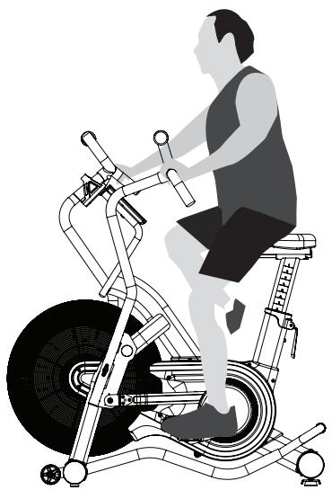
Correct cycling form
- Sit on the cycle, with your feet on the pedals and inside the pedal straps
- Ensure that the seat height is adjusted correctly - you should be stable and balanced whilst on the saddle. The basic rule for getting the seat height right is that as the pedal reaches its lowest point, the leg is almost straight.
- Try to ensure that your back is straight whilst exercising, especially for long periods.
Heart Rate Training
To get the most out of your new piece of fitness equipment and see the best results from your training you should exercise at the right level of effort, and that means listening to your heart! Working out to a target heart rate means you can direct your workout to achieve different goals:
Good health - For those wishing to improve quality of life and general well being. Your sessions will need to be done at an intensity of between 50 - 60% of your estimated maximum heart rate, should last about 30 minutes and can be done on most days of the week.
Weight loss – To see a significant reduction in body fat, your sessions must be a little more intense - between 60 and 70% of your estimated maximum heart rate. These sessions can also be performed on most days of the week for up to 30 minutes.
Improving Fitness levels –These sessions should be performed at 70 - 80% of your estimated maximum heart rate and can also involve bouts of interval training that would have your heart rate peaking for short times near your maximum heart rate level. These are intense sessions and will require at least a 48 hour rest between sessions.
How long should I exercise for?
That really depends on your current level of fitness. If you're just starting out on a new exercise program, you should start gradually and build up - do not try to do too much too quickly. 30 minutes, 3 times a week should be enough.
Don't push yourself too hard - you should never feel exhausted during or following exercise.
Calculating your target heart rate
First, you need to find your estimated maximum heart rate using the formula '220 minus your age in years'. So, if you are 35 years old your estimated maximum heart rate is:
220 - 35 = 185 beats per minute (bpm)
Next, to calculate your target heart rate, simply multiply your estimated maximum heart rate (185bpm) by the applicable percentage. So, if your goal is better heath:
185 × 60% = 111bpm
NOTE: The important issue to remember with all estimated calculations is that they are just estimates – if you don't feel comfortable exercising at your target then reduce it to a level you are comfortable with.
Note: Heart rate training requires you to monitor your heart rate throughout the workout. For this we recommend using a chest strap (if your machine has a wireless receiver) or a heart rate monitor.
Seat Adjustment
1. Seat Height:
- Rotate the pedals so that one of the pedals is in the upward position.
- Place your foot in the toe clip the pedal closest to the floor and mount the bike. Ensure that the ball of your foot is over the center of the pedal. Your leg should be slightly bent at the knee.
- If your leg is too straight or your foot cannot touch the pedal your will need to lower the seat. If your leg is bent too much you will need to raise the seat.
- Dismount the bike and release / pull the seat post adjustment handle once loosened you may slide the eat post up or down as necessary.
- When the seat is in the desired position push the seat stem adjustment handle forward to secure the seat post. Note the final position mark on the seat stem for future reference.
Seat Fore/Aft Position:
- Adjusting the fore/aft allows for a better fit. Dismount the bike and pull the seat adjustment handle and slide the seat forward or backward.
- Sit on your bike with cranks in the 3 & 9 o'clock position. Proper fore/ aft position is achieved when the small bump at the top of the shin directly below the knee cap (tibial tuberosity) is approximately over the pedal axle (at the 3 o'clock position).
- Dismount the bike and release the adjustment handle to secure the seat.
2. Pedal Strap Adjustment:
The straps of the Air Bike are designed to allow you to adjust the pedal to your individual foot size. The pedal includes spring-loaded, locking clips for easy adjustments. Follow the steps below to adjust the straps so that your foot does not slip or slide about on the pedal.
- Place the ball of each foot on the center of the pedal and under the strap.
- Rotate the pedals until one foot is in the position closest to you.
- To tighten the straps, simply pull down on the end of the strap until it fits snugly over your shoe. Make sure that the strap is secure, but not overly tight or pressing uncomfortably on your foot.
- Repeat these steps for the other foot.
- To loosen the pedal strap, press down at the top of the clip that holds the strap secure, and pull the strap up. Release the clip to lock the strap into place.
3. Comfortable Position Check:
- Now that you have established a riding position, take a few minutes to ride the bike and confirm that your position is comfortable. Start pedaling at a slow pace with your toes and knees pointed directly forward. Hold the grips lightly and in a position that allows your shoulders and upper body to relax. Pedal easily at a low resistance until your feel confident that you could ride in that position comfortably for the duration of your workout.
WARNING: The equipment is not equipped with a free wheel and therefore the moving parts cannot be stopped immediately.
NOTE: This product has an integrated speed dependent resistance / braking system.
Bevor Sie starten
Schaubenschlüssel
13/17

WERKZEUGE:
Schraubenschlüssel
E mail : service-de@carefitness.com
Satteleinstellung
- Sattelhöhe:
WARNING Heatrate制动engsmay koww youeefin topoecising iatedi
Botones "Intervalo" y "Objetivo" del programa
m = 311
luitkap

Onderdeel
nr.
Console x 1
Bevestigingsmaterial
Onderdeel
nr.
J6
M10 x 20
mm jnbus-
bout
X8
Onderdeel
nr.
48 x 30 mm
chroef
X4
Onderdeel
nr.
Afstands
ring

X2
Onder
13/14
M6
schroef

X6
m = 311
Onderdeel
nr. 12
M8 nylon
boramoer

X2
13/14
nr. 0
Smeerolie

X1