USER MANUAL 760GM-P23 MSI
760G-P43 (FX) series
MS-7699 (v1.x) Mainboard
G52-76991X1
COPYRIGHT NOTICE
The material in this document is the intellectual property of MICRO-STAR INTERNATIONAL. We take every care in the preparation of this document, but no guarantee is given as to the correctness of its contents. Our products are under continual improvement and we reserve the right to make changes without notice.
TRADEMARKS
All trademarks in this manual are properties of their respective owners.
MSI is registered trademark of Micro-Star Int'l Co., Ltd.
NVIDIA® is registered trademark of NVIDIA Corporation.
ATI® is registered trademark of ATI Technologies, Inc.
AMD is registered trademarks of AMD Corporation.
Intel is registered trademarks of Intel Corporation.
Windows® is registered trademarks of Microsoft Corporation.
AMI is registered trademark of American Megatrends, Inc.
Award® is a registered trademark of Phoenix Technologies Ltd.
Sound Blaster® is registered trademark of Creative Technology Ltd.
Realtek® is registered trademark of Realtek Semiconductor Corporation.
■ JMicron® is registered trademark of JMicron Technology Corporation.
Netware® is a registered trademark of Novell, Inc.
Lucid® is trademarks of LucidLogix Technologies, Ltd.
VIA is registered trademark of VIA Technologies, Inc.
■ ASMedia® is registered trademark of ASMedia Technology Inc.
iPad, iPhone, and iPod are trademarks of Apple Inc.
REVISION HISTORY
| Revision | Revision History | Date |
| V1.0 | First release for PCB 1.X | 2012/ 06 |
| | |
SAFETY INSTRUCTIONS
Always read the safety instructions carefully.
- Keep this User Manual for future reference.
- Keep this equipment away from humidity.
Lay this equipment on a reliable flat surface before setting it up.
- The openings on the enclosure are for air convection hence protects the equipment from overheating. Do not cover the openings.
- Make sure the voltage of the power source is at 110/220V before connecting.
- Place the power cord such a way that people can not step on it. Do not place anything over the power cord.
Always Unplug the Power Cord before inserting any add-on card or module.
All cautions and warnings on the equipment should be noted.
- Never pour any liquid into the opening that can cause damage or cause electrical shock.
If any of the following situations arises, get the equipment checked by service personnel:
The power cord or plug is damaged.
Liquid has penetrated into the equipment.
The equipment has been exposed to moisture.
- The equipment does not work well or you can not get it work according to User Manual.
The equipment has been dropped and damaged.
The equipment has obvious sign of breakage.
DO NOT LEAVE THIS EQUIPMENT IN AN ENVIRONMENT UNCONDITIONED, STORAGE TEMPERATURE ABOVE 60^ (140^) , IT MAY DAMAGE THE EQUIPMENT.
TECHNICAL SUPPORT
If a problem arises with your system and no solution can be obtained from the user's manual, please contact your place of purchase or local distributor. Alternatively, please try the following help resources for further guidance.

Visit the MSI website for technical guide, BIOS updates, driver updates, and other information: http://www.msi.com/service/download

Contact our technical staff at: http://support.msi.com
FCC-B RADIO FREQUENCY INTERFERENCE STATEMENT
This equipment has been tested and found to comply with the limits for a class B digital device, pursuant to part 15 of the FCC rules.

These limits are designed to provide reasonable protection against harmful interference in a residential installation. This equipment generates, uses and can radiate radio frequency energy and, if not installed and used in accordance with the instruction manual, may cause harmful interference to radio communications. However, there is no guarantee that interference will occur in a particular installation. If this equipment does cause harmful interference to radio or television reception, which can be determined by turning the equipment off and on, the user is encouraged to try to correct the interference by one or more of the measures listed below.
Reorient or relocate the receiving antenna.
Increase the separation between the equipment and receiver.
Connect the equipment into an outlet on a circuit different from that to which the receiver is connected.
Consult the dealer or an experienced radio/ television technician for help.
Notice 1
The changes or modifications not expressly approved by the party responsible for compliance could void the user's authority to operate the equipment.
Notice 2
Shielded interface cables and A.C. power cord, if any, must be used in order to comply with the emission limits.
VOIR LA NOTICE D'INSTALLATION AVANT DE RACCORDER AU RESEAU.

Micro-Star International
MS-7699
This device complies with Part 15 of the FCC Rules. Operation is subject to the following two conditions:
(1) this device may not cause harmful interference, and
(2) this device must accept any interference received, including interference that may cause undesired operation.
European Union:

Batteries, battery packs, and accumulators should not be disposed of as unsorted household waste. Please use the public collection system to return, recycle, or treat them in compliance with the local regulations.
Taiwan:

廢電池請回收
For better environmental protection, waste batteries should be collected separately for recycling or special disposal.
California, USA:
The button cell battery may contain perchlorate material and requires special handling when recycled or disposed of in California. For further information please visit: http://www.dtsc.ca.gov/hazardouswaste/perchlorate/
CAUTION
Danger of explosion if battery is incorrectly replaced.
Replace only with the same or equivalent type recommended by the manufacturer.
In compliance with chemical substances regulations, such as the EU REACH Regulation (Regulation EC No. 1907/2006 of the European Parliament and the Council), MSI provides the information of chemical substances in products at:
http://www.msi.com/html/popup/csr/evmptrtt_pcm.html
BSMI_EMI聲明
警告使用者
To protect the global environment and as an environmentalist, MSI must remind you that...
Under the European Union ("EU") Directive on Waste Electrical and Electronic Equipment, Directive 2002/96/EC, which takes effect on August 13, 2005, products of "electrical and electronic equipment"

cannot be discarded as municipal wastes anymore, and manufacturers of covered electronic equipment will be obligated to take back such products at the end of their useful life. MSI will comply with the product take back requirements at the end of life of MSI-branded products that are sold into the EU. You can return these products to local collection points.
DEUTSCH
Thank you for choosing the 760GA-P43 (FX)/ 760G-P43 (FX) series (MS-7699 v1.x) ATX mainboard. These series are designed based on AMD® 760G & SB710 chipset for optimal system efficiency. Designed to fit the advanced AMD® processor in AM3+ package, these series deliver a high performance and professional desktop platform solution.
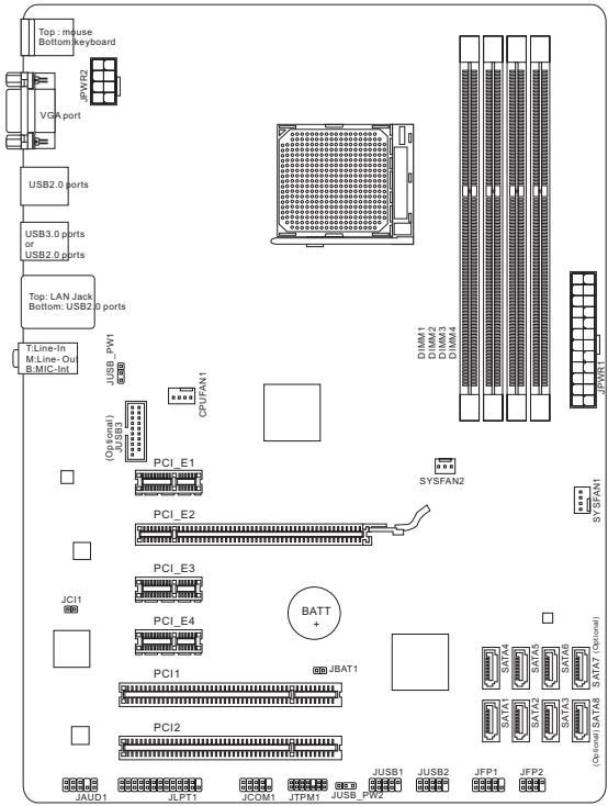
Layout
SPECIFICATIONS
Processor Support
Support AMD Phenom™ II / Athlon™ II / Sempron™ processors for AM3+ socket
Chipset
North Bridge: AMD® 760G chipset
South Bridge: AMD® SB710 chipset
Memory Support
4x DIMMs support for DDR3-1866*OC)/ 1600/ 1333/ 1066 MHz up to 32GB max
Supports Dual-Channel mode
LAN
Supports LAN 10/ 100/ 1000 by Realtek ^念 8111E
Audio
Chip integrated by Realtek® ALC887
Supports 8-channels audio out
Compliant with Azalia 1.0 Spec
SATA
6x SATA 3Gb/s ports (SATA1~6) by AMD® SB710
2x SATA 6Gb/s ports (SATA7~8) by Asmedia® ASM1061 (760GA-P43 (FX))
RAID
SATA 1~6 support RAID 0/1/10 or JBOD mode by AMD® SB710
USB 3.0 (760GA-P43 (FX))
2x USB 3.0 rear IO ports by RENESAS 720201
1x USB 3.0 onboard connector by RENESAS 720201
Connectors
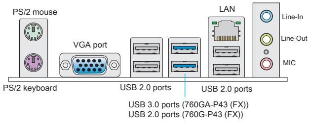
Back panel
- 1x PS/2 mouse port
- 1x PS/2 keyboard port
- 1x VGA port
- 4x USB 2.0 ports (760GA-P43 (FX))/ 6x USB 2.0 ports (760G-P43 (FX))
- 2x USB 3.0 ports (760GA-P43 (FX))
- 1x LAN jack
- 3x flexible audio jacks
On-Board Connectors
- 2x USB 2.0 connectors
- 1x USB 3.0 connector (760GA-P43 (FX))
- 1x Front Panel Audio connector
- 1x Parallel Port connector
- 1x Serial Port connector
- 1x TPM connector
- 1x Chassis Intrusion connector
Slots
1x PCIe 2.0 x16 slot
3x PCIe 2.0 x1 slots
2xPCI slots
ATX (30.48 cm × 22.25 cm)
Mounting Screw Hole
6 mounting holes

For the latest information about CPU, please visit
http://www.msi.com/service/cpu-support

For more information on compatible components, please visit http://www.msi.com/service/test-report
If you need to purchase accessories and request the part numbers, you could search the product web page and find details on our web address below http://www.msi.com/index.php
The rear panel provides the following connectors:
HARDWARE SETUP
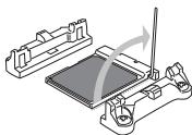
CPU & Cooler Installation for AM3+
When installing a CPU, always remember to install a CPU cooler. A CPU cooler is necessary to prevent overheating and maintain system stability. Follow the steps below to ensure correct CPU and CPU cooler installation. Wrong installation can damage both the CPU and the mainboard.
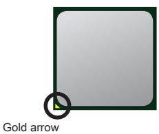
The surface of AM3+ CPU.
Remember to apply some thermal paste on it for better heat dispersion.
Follow the steps below to install the CPU & cooler correctly.
- Pull the lever sideways away from the socket. Make sure to raise the lever up to a 90-degree angle.
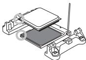
- Look for the gold arrow of the CPU. The gold arrow should point as shown in the picture. The CPU can only fit in the correct orientation.
- If the CPU is correctly installed, the pins should be completely embedded into the socket and can not be seen. Please note that any violation of the correct installation procedures may cause permanent damages to your mainboard.
- Press the CPU down firmly into the socket and close the lever. As the CPU is likely to move while the lever is being closed, always close the lever with your fingers pressing tightly on top of the CPU to make sure the CPU is properly and completely embedded into the socket.
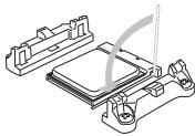
- Position the cooling set onto the retention mechanism. Hook one end of the clip to hook first.
- Then press down the other end of the clip to fasten the cooling set on the top of the retention mechanism. Locate the Fix Lever and lift up it.
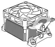
- Fasten down the lever.
- Attach the CPU Fan cable to the CPU fan connector on the mainboard.

IMPORTANT
- While disconnecting the Safety Hook from the fixed bolt, it is necessary to keep an eye on your fingers, because once the Safety Hook is disconnected from the fixed bolt, the fixed lever will spring back instantly.
- Confirm that the CPU cooler has formed a tight seal with the CPU before booting your system.
- Please refer to the documentation in the CPU cooler package for more details about CPU cooler installation.
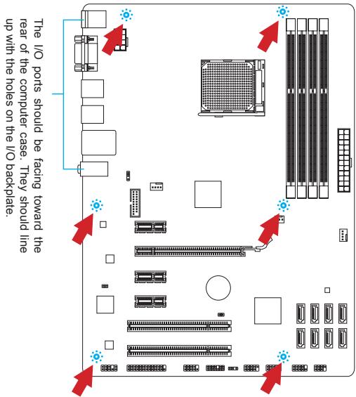
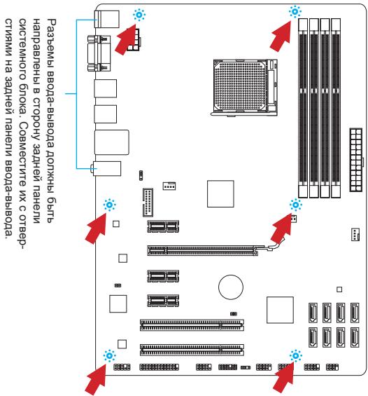
Mounting Screw Holes
When installing the mainboard, first install the necessary mounting stands required for a mainboard on the mounting plate in your computer case. If there is an I/O back plate that came with the computer case, please replace it with the I/O backplate that came with the mainboard package. The I/O backplate should snap easily into the computer case without the need for any screws. Align the mounting plate's mounting stands with the screw holes on the mainboard and secure the mainboard with the screws provided with your computer case. The locations of the screw holes on the mainboard are shown below. For more information, please refer to the manual that came with the computer case.

IMPORTANT
- Install the mainboard on a flat surface free from unnecessary debris.
- To prevent damage to the mainboard, any contact between the mainboard circuitry and the computer case, except for the mounting stands, is prohibited.
- Please make sure there are no loose metal components on the mainboard or within the computer case that may cause a short circuit of the mainboard.
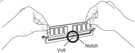
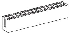
Installing Memory Modules
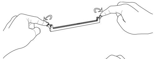
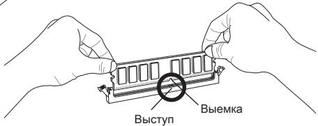
- Unlock the DIMM slot by pushing the mounting clips to the side. Vertically insert the memory module into the DIMM slot. The memory module has an off-center notch on the bottom that will only allow it to fit one way into the DIMM slot.
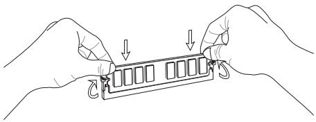
- Push the memory module deep into the DIMM slot. The plastic clips at each side of the DIMM slot will automatically close when the memory module is properly seat and an audible click should be heard.
- Manually check if the memory module has been locked in place by the DIMM slot's side clips.


IMPORTANT
- To ensure system stability, memory modules must be of the same type and density in Dual-Channel mode.
- Always insert memory modules in the DIMM1 slot first.
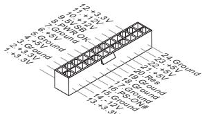
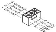
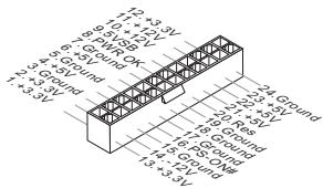
JPWR1:ATX24-Pin Power Connector
This connector allows you to connect an ATX 24-pin power supply. To connect the ATX 24-pin power supply, align the power supply cable with the connector and firmly press the cable into the connector. If done correctly, the clip on the power cable should be hooked on the mainboard's power connector.
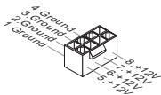
JPWR2:ATX8-Pin Power Connector
This connector provides 12V power to the CPU..

IMPORTANT
Make sure that all the power cables are securely connected to a proper ATX power supply to ensure stable operation of the mainboard.
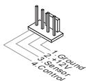
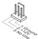
CPUFAN1, SYSFAN1, SYSFAN2: Fan Power Connectors
The fan power connectors support system cooling fans with +12V. If the mainboard has a System Hardware Monitor chipset on-board, you must use a specially designed fan with a speed sensor to take advantage of the CPU fan control. Remember to connect all system fans. Some system fans may not connect to the mainboard and will instead connect to the power supply directly. A system fan can be plugged into any available system fan connector.
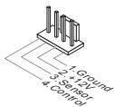
CPUFAN1
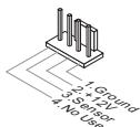
SYSFAN1
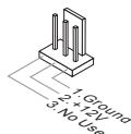
SYSFAN2
SATA1~8: Serial ATA Connector (SATA7~8 are for 760GA-P43 (FX))
This connector is a high-speed Serial ATA interface port. Each connector can connect to one Serial ATA device. Serial ATA devices include disk drives (HD), solid state drives (SSD), and optical drives (CD/DVD/Blu-Ray).


IMPORTANT
- Please do not fold the Serial ATA cable at a 90-degree angle. Data loss may result during transmission otherwise.
- SATA cables have identical plugs on either sides of the cable. However, it is recommended that the flat connector be connected to the mainboard for space saving purposes.
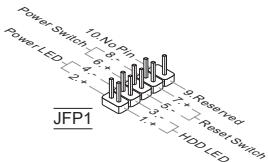
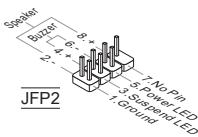
JFP1, JFP2: Front Panel Connectors
These connectors are for electrical connection to the front panel switches and LEDs. The JFP1 is compliant with Intel® Front Panel I/O Connectivity Design Guide.
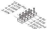
JCOM1: Serial Port Connector
This connector is a 16550A high speed communication port that sends/receives 16 bytes FIFOs. You can attach a serial device.
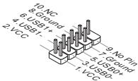
JUSB1, JUSB2: USB 2.0 Expansion Connector
This connector is designed for connecting high-speed USB peripherals such as USB HD s, digital cameras, MP3 players, printers, modems, and many others.
JUSB3: USB 3.0 Expansion Connector (760GA-P43 (FX))
The USB 3.0 port is backwards compatible with USB 2.0 devices. It supports data transfer rates up to 5Gbits/s (SuperSpeed).
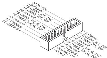

IMPORTANT
- Note that the VCC and GND pins must be connected correctly to avoid possible damage.
- To use a USB 3.0 device, you must connect the device to a USB 3.0 port through an optional USB 3.0 compliant cable.
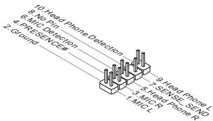
JAUD1 : Front Panel Audio Connector
This connector allows you to connect the front audio panel located on your computer case. This connector is compliant with the Intel® Front Panel I/O Connectivity Design Guide.
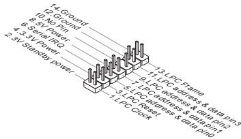
JTPM1: TPM Module Connector
This connector connects to a optional TPM (Trusted Platform Module). Please refer to the TPM security platform manual for more details and usages.
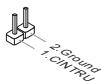
JCI1: Chassis Intrusion Connector
This connector connects to the chassis intrusion switch cable. If the computer case is opened, the chassis intrusion mechanism will be activated. The system will record this intrusion and a warning message will flash on screen. To clear the warning, you must enter the BIOS utility and clear the record.
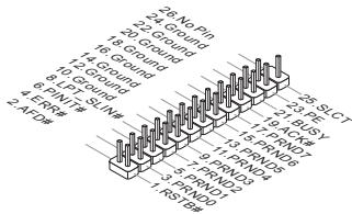
JLPT1: Parallel Port Connector
This connector is used to connect an optional parallel port bracket. The parallel port is a standard printer port that supports Enhanced Parallel Port (EPP) and Extended Capabilities Parallel Port (ECP) mode.
JBAT1: Clear CMOS Jumper
There is CMOS RAM onboard that is external powered from a battery located on the mainboard to save system configuration data. With the CMOS RAM, the system can automatically boot into the operating system (OS) every time it is turned on. If you want to clear the system configuration, set the jumper to clear the CMOS RAM.

Keep Data

Clear Data

IMPORTANT
You can clear the CMOS RAM by shorting this jumper while the system is off. Afterwards, open the jumper. Do not clear the CMOS RAM while the system is on because it will damage the mainboard.
JUSB_PWM1,JUSB_PWM2:USB power Jumpers
These jumpers are used to select USB 2.0 ports powered by VCC5 or 5VSB. Set to 5VSB if you want the USB 2.0 ports provide power in standby mode.

JUSB_PWM1 (for rear USB 2.0 ports)

Keep USB power to VCC5
Keep USB power to 5VSB
JUSBPW2

(for on-board USB 2.0 connectors)


Keep USB power to VCC5
Keep USB power to 5VSB

IMPORTANT
If you set the jumper to 5VSB, the power supply must be able to provide at least 2A currents.
PCIe (Peripheral Component Interconnect Express) Slot The PCIe slot supports the PCIe interface expansion card.
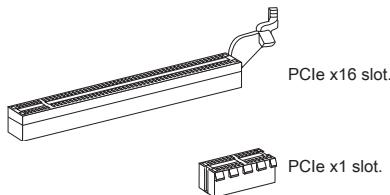
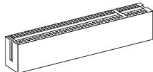
PCI (Peripheral Component Interconnect) Slot
The PCI slot supports LAN card, SCSI card, USB card, and other add-on cards that comply with PCI specifications.

IMPORTANT
When adding or removing expansion cards, always turn off the power supply and unplug the power supply power cable from the power outlet. Read the expansion card's documentation to check for any necessary additional hardware or software changes.
PCI Interrupt Request Routing
IRQ, or interrupt request lines, are hardware lines over which devices can send interrupt requests to the processor. The PCI IRQ pins are typically connected to the PCI bus pins as followed:
| Order Slot | 1 | 2 | 3 | 4 |
| PCI1 | INT A# | INT B# | INT C# | INT D# |
| PCI2 | INT B# | INT C# | INT D# | INT A# |
Power on the computer and the system will start POST (Power On Self Test) process. When the message below appears on the screen, press key to enter Setup.
If the message disappears before you respond and you still wish to enter Setup, restart the system by turning it OFF and On or pressing the RESET button. You may also restart the system by simultaneously pressing , , and keys.

IMPORTANT
The items under each BIOS category described in this chapter are under continuous update for better system performance. Therefore, the description may be slightly different from the latest BIOS and should be held for reference only.
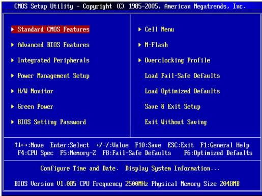
Standard CMOS Features
Use this menu for basic system configurations, such as time, date etc.
Advanced BIOS Features
Use this menu to setup the items of special enhanced features.
Integrated Peripherals
Use this menu to specify your settings for integrated peripherals.
Power Management Setup
Use this menu to specify your settings for power management.
H/W Monitor
This entry shows the status of your CPU, fan, warning for overall system status.
Green Power
Use this menu to specify the power phase.
BIOS Setting Password
Use this menu to set BIOS setting Password.
Use this menu to specify your settings for frequency/voltage control.
M-Flash
Use this menu to read/ flash the BIOS from USB media device.
Overclocking Profile
Use this menu to save/ load your settings to/ from CMOS for BIOS.
Load Fail-Safe Defaults
Use this menu to load the BIOS default values that are factory settings for system operations.
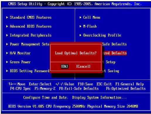
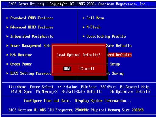
Load Optimized Defaults
Use this menu to load factory default settings into the BIOS for stable system performance operations.
Save & Exit Setup
Save changes to CMOS and exit setup.
Exit Without Saving
Abandon all changes and exit setup.

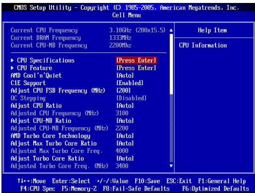
Current CPU/ DRAM/ CPU-NB Frequency
It shows the current frequency of CPU/ DRAM/ CPU-NB. Read-only.
CPU Specifications
Press to enter the sub-menu. This submenu shows the information of installed CPU.
CPU Technology Support
Press to enter the sub-menu. This sub-menu shows the technologies that the installed CPU supported.
CPU Feature
Pressto enter the sub-menu:
AMD Cool'n'Quiet
The Cool'n'Quiet technology can effectively and dynamically lower CPU speed and power consumption.
C1E Support
To enable this item to reduce the CPU power consumption while idle. Not all poressors support Enhanced Halt tate (C1E).
SVM Support
This item allows you to enable/disable the AMD SVM (Secure Virtual Machine) Technology.
AMD Cool'n'Quiet
The Cool'n'Quiet technology can effectively and dynamically lower CPU speed and power consumption.

IMPORTANT
To ensure that Cool'n'Quiet function is activated and will be working properly, it is required to double confirm that:
- Run BIOS Setup, and select Cell Menu. Under Cell Menu, find AMD Cool'n'Quiet, and set this item to "Enabled".
- Enter Windows, and select [Start]->[Settings]->[Control Panel]->[Power Options]. Enter Power Options Properties tag, and select Minimal Power Management under Power schemes.
C1E Support
To enable this item to reduce the CPU power consumption while idle. Not all poressors support Enhanced Halt tate (C1E).
Adjust CPU FSB Frequency (MHz)
This item allows you to select the CPU Front Side Bus clock frequency (in MHz).
OC Stepping
This item will be enabled after you set the overclocking frequency in the "Adjust CPU FSB Frequency (MHz)". And the following items will appear. This items will help the system to overclock step by step after system booting up.
Start OC Stepping From (MHz)
This item is used to set the initial base clock. The system will boot with the initial base clock, and start to overclock from initial base clock to set base clock that you set in "Adjust CPU FSB Frequency (MHz)" step by step.
OC Step
This item is used to set how many steps for base colck overclocking.
OC Step Count Timer
This item is used to set the buffer time for every step.
Adjust CPU Ratio
This item is used to adjust CPU clock multiplier (ratio). It is available only when the processor supports this function.
Adjusted CPU Frequency (MHz)
It shows the adjusted CPU frequency. Read-only.
Adjust CPU-NB Ratio
This item is used to adjust CPU-NB ratio.
Adjusted CPU-NB Frequency (MHz)
It shows the adjusted CPU-NB frequency. Read-only.
AMD Turbo Core Technology
This technology automatically increases the frequency of active CPU cores to improve performance.
Adjust Max Turbo Core Ratio
This item is used to adjust the maximum CPU turbo core ratio.
Adjusted Max Turbo Core Freq.
It shows the adjusted maximum CPU turbo core frequency. Read-only.
Adjust Turbo Core Ratio
This item is used to adjust the CPU turbo core ratio.
Adjusted Turbo Core Freq. (MHz)
It shows the adjusted CPU turbo core frequency. Read-only.
Unlock CPU Core
This item allows you to unlock the additional cores, you could set it [Enabled] and then set Advanced Clock Calibration [Auto] in order to be able to activate the processor cores.
Advanced Clock Calibration
This item is for overclock. Setting to [Auto] allows you to set the CPU Ratio higher. It is available only when the processor supports this function.
CPU Core Control
This item is used to control number of CPU cores. When set to [Auto], the CPU will operate under the default number of cores. When set to [Manual], you will be able to enable/disable the specific CPU core.
Core X
These items are used to enable/disable the core X.
OC Genie Lite
Setting this item to [Enabled] allows the system to detect the maximum FSB clock and to overclock automatically. If overclocking fails to run, you can try the lower FSB clock for overclocking successfully.
Memory-Z
Pressto enter the sub-menu.
Press to enter the sub-menu. This sub-menu displays the information of installed memory.
Advance DRAM Configuration
Press to enter the sub-menu.
DRAM Timing Mode
Select whether DRAM timing is controlled by the SPD (Serial Presence Detect) EEPROM on the DRAM module. Setting to [Auto] enables DRAM timings and the following "Advance DRAM Configuration" sub-menu to be determined by BIOS based on the configurations on the SPD. Selecting [Manual] allows users to configure the DRAM timings and the following related "Advance DRAM Configuration" sub-menu manually.
FSB/DRAM Ratio
This item allows you to select the ratio of FSB/ DRAM.
Adjusted DRAM Frequency (MHz)
It shows the adjusted Memory frequency. Read-only.
HT Link Control
Press to enter the sub-menu.
HT Incoming/Outgoing Link Width
These items allow you to set the Hyper-Transport Link width. Setting to [Auto], the system will detect the HT link width automatically.
HT Link Speed
This item allows you to set the Hyper-Transport Link speed. Setting to [Auto], the system will detect the HT link speed automatically.
Adjusted HT Link Frequency (MHz)
It shows the adjusted HT Link frequency. Read-only.
Auto Disable DRAM/PCI Frequency
When set to [Enabled], the system will remove (turn off) clocks from empty DRAM/PCI slots to minimize the electromagnetic interference (EMI).
CPU VDD Voltage (V)/ CPU-NB VDD Voltage (V)/ DRAM Voltage
These items are used to adjust the voltages.
Spread Spectrum
This function reduces the EMI (Electromagnetic Interference) generated by modulating clock generator pulses..

IMPORTANT
- If you do not have any EMI problem, leave the setting at [Disabled] for optimal system stability and performance. But if you are plagued by EMI, select the value of Spread Spectrum for EMI reduction.
- The greater the Spread Spectrum value is, the greater the EMI is reduced, and the system will become less stable. For the most suitable Spread Spectrum value, please consult your local EMI regulation.
- Remember to disable Spread Spectrum if you are overclocking because even a slight jitter can introduce a temporary boost in clock speed which may just cause your overclocked processor to lock up.
Load Optimized Defaults
You can load the default values provided by the mainboard manufacturer for the stable performance.
中国
#
USB 3.0 (760GA-P43 (FX))
■ RENESAS 720201上之USB3.0后IOF2
■ RENESAS 720201eの用USB3.0上部制製1個尺寸
K
-
-PS/2 叶云s 1
-PS/2 尔邦德托1个
- VGA 1000
- USB 2.0 扑旦 4 内 (760GA-P43 (FX))/ USB 2.0 扑旦 6 内 (760G-P43 (FX))
- USB 3.0 扎贝2个(760GA-P43 (FX))
- LAN 1
- 普勒镇市上县区3个
ATX (30.48 cm X 22.25 cm)
首中
长

CPU上大中
http://www.msi.com/service/cpu-support将添加此项。

赫希卡能有本
http://www.msi.com/service/test-report中止承诺
此 knteTET是的,私SIRIATE ATA ITeTpeiTS foTepfseuAougclnla.当knteTET是hata 的SIRIATE ATAJSTeHJFJFJFJFJFJFJFJFJFJFJFJFJFJFJFJFJFJFJFJFJFJFJFJFJFJFJFJFJFJFJFJFJFJFJFJFJFJFJFJFJFJFJFJFJFJFJFJFJFJFJ


音义
*SIRIATAPAKIOIJIH0DLOREKJITAKHEO.该等既用函合多EHTaG高
SATA KEGHEM的華歌多號上達日中普拉克夫如志[可]中公关刻字将用,
JFP1,JFP2:
PCIe (Peripheral Component Interconnect Express) 會異
PCIe 也登录在PCIe InTeIeIeIs 针旨卡德到 责可

PCI (Peripheral Component Interconnect) 会灵
CMOS Setup Utility - Copyright (C) 1985-2005, American Negatrends, Inc.
Standard CHOS Features
Advanced BIOS Features
Integrated Peripherals
Power Management Setup
H/V Monitor
Green Power
BIOS Setting Password
Cell Menu
N-Flash
Overclocking Profile
Load Fail-Safe Defaults
Load Optimized Defaults
Save 8 Exit Setup
Exit Without Saving
十 :MoveEnterSelect ^ 一 / < - / ValueF10:SaueESC:ExitF1:GeneralHelp F4:CPU SpecF5:Memory-2F:F0Fall-Safe Defaults F6:Optimized Defaults
Configure Time and Date. Display System Information...
BIOS Version U1.0B5 CPU Frequency 2500MHz Physical Memory Size 204MB
Standard CMOS Features
i
Advanced BIOS Features
Ie MeTNDuR saUroHrOgEoFIOgIgNIOgNIOgNIOgNIOgNIOgNIOgNIOgNIOgNIOgNIO
Integrated Peripherals
iEeHnTtJF 1
Power Management Setup
i
H/W Monitor
i
Green Power
iEeHnTtJF 1
BIOS Setting Password
iEe 1
iEeHnueoHaeuHuaHuaHuaHuaHuaHuaHuaHuaHuaHuaHuaHuaHuaHuaHuaHuaHuaHuaHuaHuaHuaHuaHuaHuaHuaHuaHuaHuaHuaHuaHuaHuaHuaHuaHuaHuaHuaHuaHuaHuaHuaHuaHuaHuaHuaHuaHuaHuaHuaHuaHUA
M-Flash
iEeH 1
Overclocking Profile
iEeHnue HBIOS 5000 CMOS 1000 CMOS 1000
Load Fail-Safe Defaults
Current CPU/ DRAM/ CPU-NB Frequency
CPU Technology Support
普通从串串串串串串串串串串串串串串串串串串串串串串串串串串串串串串串串串串串串串串串串串串串串串串串串串串串串串串串串串串串串串串串串串串串串串串串串串串串串串串串串串串串串串串串串串串串串串串串串串串串串
CPU Feature
将“”列起来,用“+”表示。
AMD Cool'n'Quiet
Adjust CPU FSB Frequency (MHz)
i
OC Stepping
“CPUFSB 未加分(MHz) 正当”→载上衣衣衣衣衣衣衣衣衣衣衣衣衣衣衣衣衣衣衣衣衣衣衣衣衣衣衣衣衣衣衣衣衣衣衣衣衣衣衣衣衣衣衣衣衣衣衣衣衣衣衣衣衣衣衣衣衣衣衣衣衣衣衣衣衣衣衣衣衣衣衣衣衣衣衣衣衣衣衣衣衣衣衣衣衣衣衣衣衣衣衣衣衣衣衣衣衣衣衣衣
Start OC Stepping From (MHz)
此哈藏的本应如,H
OC Step
此在回录中,亦有如用。
OC Step Count Timer
i
Adjust CPU Ratio
Adjusted CPU Frequency (MHz)
i
Adjust CPU-NB Ratio
I 表示登录到CPU-NB的用户。
Adjusted CPU-NB Frequency (MHz)
Adjusted Max Turbo Core Freq.
i
Adjust Turbo Core Ratio
Adjusted Turbo Core Freq. (MHz)
i
Unlock CPU Core
Advanced Clock Calibration
Adjusted DRAM Frequency (MHz)
这句是关于“如果”(如果)的。
HT Link Control
将确定后生成的页面自动存入到文件中。
HT Incoming/Outgoing Link Width
Adjusted HT Link Frequency (MHz)
USB 3.0 (760GA-P43 (FX))
http://www.msi.com/service/cpu-support

Emplacement PCI (Peripheral Component Interconnect)
Advanced BIOS Features
Integrated Peripherals
BIOS Setting Password
Overclocking Profile
Current CPU/ DRAM/ CPU-NB Frequency
CPU Technology Support
Adjust CPU FSB Frequency (MHz)
Start OC Stepping From (MHz)
Adjusted CPU Frequency (MHz)
Adjusted CPU-NB Frequency (MHz)
Adjusted Max Turbo Core Freq.
Adjusted Turbo Core Freq. (MHz)
Advanced Clock Calibration
Adjusted DRAM Frequency (MHz)
HT Incoming/Outgoing Link Width
Adjusted HT Link Frequency (MHz)
USB 3.0 (760GA-P43 (FX))
http://www.msi.com/service/cpu-support

JFP1, JFP2: Frontpanel Anschlüsse
CMOS Setup Utility - Copyright (C) 1985-2005, American Megatrends, Inc.
Standard CMOS Features
Advanced BIOS Features
Integrated Peripherals
Power Management Setup
H/U Monitor
Green Power
BIOS Setting Password
Cell Menu
N-Flash
Overclocking Profile
Load Fail-Safe Defaults
Load Optimized Defaults
Save 8 Exit Setup
Exit Without Saving
```c
11->Move Enter:Select +/-/Value F0:Saue ESC:Exit F1:General Help
F4:CPU Spec F5:Memory-2 F0:Fall-Safe Defaults F6:Optimized Defaults
Configure Time and Date. Display System Information...
BIOS Version U1.0BS CPU Frequency 2500MHz Physical Memory Size 204MB
Standard CMOS Features
Advanced BIOS Features
Integrated Peripherals
BIOS Setting Password
Overclocking Profile
Current CPU/ DRAM/ CPU-NB Frequency
CPU Technology Support
Adjust CPU FSB Frequency (MHz)
Start OC Stepping From (MHz)
Adjusted CPU Frequency (MHz)
Adjusted CPU-NB Frequency (MHz)
Adjusted Max Turbo Core Freq.
Adjusted Turbo Core Freq. (MHz)
Advanced Clock Calibration
Adjusted DRAM Frequency (MHz)
HT Incoming/Outgoing Link Width
Adjusted HT Link Frequency (MHz)
TEXHINUCKNEXAPAKTEPNUCTIKN
PoiDJIeRkKa npOceccopoB
Плобджка роцешсоров AMD® Phenom™ II / Athlon™ II / Sempron™ дяразьема AMD3+
Ha6op MmKpocxem
CebepnMoCT:Mn-Ha6Op AMD760G
IOxHbIMocT:Mn-Ha6op AMDSB710
Poiepkka Moyniem namrtn
4Xn3da DIMM noIaepKbAoiT oMyni DDR3-1866*OC/ 1600/ 1333/ 1064 MTu (MAcMKmBnaJIbEMKoCTb 3Gf)
IopndepkKa DByXKaHaNbHoro peKIma
JBC
Iopndepkka JBC 10/100/1000 c nomoubkoHTpOllnepa Realtek ^ 念 8111E
3Byk
BcTpoEHnHa MmKpOcxema Realtek ALC887
Iopndepkka 8-kaHabHoro 3BykoBOrO BbIXoDa
CoBmecTImOcTb CO cTaHdapTom Azalia 1.0
INHepdncSATA
6x pa3bemOB SATA 3 GB/c (SATA1~6) ha minkpocxemax AMD® SB710
2x nopta SATA 6 Γ6/c (SATA7~8) Na MInpocxeme Asmedia® ASM1061 (760GA-P43 (FX))
RAID
SATA 1-6 noДерхиBaeТ ржIM RAID O/1/10 ИИ NBOD ha MmKpOcXeMe AMD®SB710
USB 3.0 (760GA-P43 (FX))
2x npota Bvoda-bvboDa USB 3.0 na 3aDne naneHn c mncnoB3oBAHnEM RENESAS720201
1x pa3bem USB 3.0 Ha nlaTe c nCnoJb3ObaHnem RENESAS 720201
Pa3beMbl
Pa3beMbHa 3aHne naHeJI
Pa3bemblHa nntate
- 2x pa3bema USB 2.0
- 1x pa3bem USB 3.0 (760GA-P43 (FX))
- 1x aydnopazbem Ha nepedne nane
- 1x pa3bem npapannelbHoro nopta
- 1x pa3bem nocledoBateIbHoro npota
- 1x TPM pa3beM
- 1x pa3bem DaTUnKa OTKpbIbAHnK KOpnyCa
Tne3da
1x rhe3do PCIe 2.0 x16
3x rHe3da PCIe 2.0 x1
2x rHe3daPCI
ΦopM-ΦakTop
ATX (30,48 X 22,25 cm)
OTBepCTHe IOd yCTaHOBOUHbI BnHT
6 O TBepCTn DnKpeHnneHn

TocneHnCBeDHeN O noDdepKNaebMbx LcM.
http://www.msi.com/service/cpu-support

ДОПОНТENБЕ CBDEнИ O COBMECTMbIX COMOHENTAX CM. И ВБС-стANUE
http://www.msi.com/service/test-report
OTBepCTnI IOYcTaHOBOUHbIe BnHTbI
Дагу статовки материнский паты на мостахони пате сстесногд Stokа chachaya установп постесногд Stokи.Есни в комплент Коставки сстесногд Stokи 6dOKA BXOДNT 3dJHЯ паимь BAODA-BbIbOda,Змэнгете здддддддддддддддддддддддддддддддддддддддддддддддддддддддддддддддддддддддддддддддддддддддддддддддддддд徳 STOKИ 6dJDA TcHANABINAECTCR B cStetHMOM 6dOKe KMПЛБТЕРа 6dmpMENHЯ BINTOB.COBmTEITE ystahobouhryte StOKI MONTAHXHПпаты COTBEPCTNIM NOД qYSTAHOBUHBy BINTHy MA MATePHCKON PNTA 3aKZPENHTE MATEPHCNCKYU pNTAY BHTAMN,KOTOPBE NOSTABTOKC BMECTE C cStETMHbIM 6dOKOM.HnKe NOKa3AZHO pACNOONEXHE OTBEPCTNI QD YsTaHOBOHy BINTHy DOnJIHNITeNBHyU INHΦOpMaUHcM.BpyKOBOCTBe K CStENTMOHY 6dOKY.

BHIMMAHNEI
* PonoKInTe MaTePNHckyo nnaty Ha poBHyIO nCHTyIO NOBepxHOCTb.
*BoIb6eXaHneNOBpeXdHnMaTepuHcKoI pntbl,3akpePNIyTe 3NeKtPOHc HOMKoHEHbI Ha yctaHOBOUbIX cToJkAX, I36eRa INC oPnPkoCHOBHeN C CNTeMHbIM bOJKOM.
*PnOeBpTe HAdExoHCTb KpeNtneBCExC MeTAnIuHeCKHX KOMnHOHTOB Ha MATEPHNCKO PnATE mN BuTyPr CnCTmHOrO BNoka. HeaKpeNneHbIe Detanu MORYT PnEBCTU K KOPTOKMYA 3MbKaHAnIO MATEPHNCKO PnATbl.
YctaHOBkaMOdyIeIITAMrTNI
- OToDbInbTe B cToPoHy KNEMMbIe 3azMmbl IN ToKpOHe THe3Do DIMM. BeptnKaJIbHo BCTABBe TMouMbI naMaTn B rHe3Do DIMM. B HnKHeJ acTn MOyJn MaNtNi MmEeTc CMeUeHHa T OeHTpa BByEMKa IJa nPaBvInbHO yctahOBKn MoDyJr B rHe3Do DIMM.
- YctahOBtteMoDyIb naTyrnB rHe3do DIMM do ynpa. Ipn npabAnbHom nopoKEnH moJyra naTyrn B rHe3e daactKOBBe 3auenKn c o6eX CTOPOHr He3da DIMM abotmAtneck 3auenKnBAOTCT.
- Y6eIaTeTcB, YTO MoIyNb nAmayrN 3aΦnKnPoBaH B rHe3De DIMM 3aUeNkamn rHe3Da.


BHIMAHHE!
*IgnoepeHnnaCTabnlbHOpaB0tbcNCTeMbIBdyXKaHaHbHompeXHMe yctahabNBAOTcMoDynnNaMaTnOndhakOBOroTtnaHEMKOctn.
* Bcerda NaHnHaTe yctaHOBky moynen namrtn C rHe3da DIMM1.
JPWR1:24-KoHTaKThbI pa3bEm nTaNHn ATX
3TOT pa3bem pnpdHa3nueH dIy npDkiuOHeN 24-KoHTaKTHOrO 6JloKa NiTaHnIg ATX. IINp NpDKIIOHeHNe 6JNOA NITAHNl ATX c 24-KoHTaKThbIM pa3bEMOM COMeCTHte Ka6eB nPiTaHc n pa3bEmom n IpocHo 3aKePnTe erO. PIn npabINbHOM bYiOpINHEHm NpDkiuOHeHn 3aUeNkHa Ka6eBe NITAHNl 3aKePnJIeTcB CnIOLOBM pa3bEme MaTePHNcK OIIaTbI.
JPWR2:8-KoHTaKTHbI pa3bEm nTahnA ATX
3ToT pa3bem o6ecneuBaet npaay 12 B nHTaHn Ha npoceccop.

BHIMMAHVEI
ДлбОБЕСЕЧЕНИ CTÁBЛБНОРаБОТь CBNTÉМΟ ПЛТВИ РОВЕРБЕ ТЕ ДAZEKHOCTБ NOДКПЮЕЗИ ВСЕ KABENEI NITAHNY K COOTBTCTBYUÇEMY 6LOKY NITAHNY ATX.
CPUFAN1, SYSFAN1, SYSFAN2: Pa3bEmbl nItaHnB BeHTIgTOpOB
Pa3eMbI NITAHNA BEHTNITATOPB NOIDepjXnBAOT BEHTNITATOpb c NITAHmE +12 B.EcHnHa CNTHEMOHnI nIaYCTAHOBHeA MKNPOCXema annapathoro MOHNTOPHRA, Heo6xOIMMo INCNtB3OaBTc CNEaJIbHbIE BEHTNITATOpb c DaTHKAMMI CKOPOCTn IINCNIOB3OaHMy FyHKUIM ynpABNeHry BEHTNITOPPAM. O63aTeMbHO NOkKnIOHTe BCE CNTeMhBE BHTNITATOpb. HeKOTopbie CNTeMhBE BHTNITATOpb NoIKNOVAOTc HE K MaTEpHcKO nIaTae, a HAnpMaHyo K UTOCHNY KNTAHNA. BEHTNITATOpb CNTeMbI NOkKnIOuAOTc K CBO6OHNbIM pa3beMam dANBEHTNITATOpB.
CPUFAN1

SYSFAN1
SYSFAN2
SATA1~8:Pa3bEm Serial ATA (SATA7~8 nla 760GA-P43 (FX))
Tne3o PCI (Peripheral Component Interconnect)
THe3DPCO Ns0BnAHTcYCTAHOBHTbNtAaLNC, SCSU, BnIg AnpyrE donoHnHmTebnHbue nNtBpTaCpaHneHHKOTOpBie COoBETCTBYOT cneuHkMauKl PCi.

BHIMAHHEI
IpeyctahOBKOINN3BNEeHEmnpatpssnepnHryb6ntecb,TOIHy npTnAHOYKIOHTN3EKNTHcckO cETNI.PoNTHTeDOKMeHTaUHO HA kapty paSSnEPnHnBvblNOHTHe NOE6XODMlbE donONNHtEnbHbIe annpaTHbI INPpOrAMMbHNeIMeHEHNNJDAHNOH KaptbI.
Mapuytnaun 3anpocob npepbBaHnPCI
IRQ(LHINH3anpoce npebbAHA)yBIAOTcA anpaTHbIMn HINHMn,NO KOTOpBM yUPOCTBa MOnT noCbIna nPoCEtAcTe 2AnpoCbHa npebbAHA. CToIaAPThOE noDKNIOueHene PCI IRQ K KOHTAKCe TAMnHbPIK oNkAHO HNKe
| Порадок
Гнебуо | 1 | 2 | 3 | 4 |
| PCI1 | INT A# | INT B# | INT C# | INT D# |
| PCI2 | INT B# | INT C# | INT D# | INT A# |
BKJHOUHTe KOMbIbTepe ndoJIteBc Hauana npocdApbl cAmOTeCTNPOBAHN A POST (Power On Self Test).Pnp noBaIeHnHa kApae Coo6eHnna, npBeDeHnHO Hxne, hAnKMTe KnabuH y 3n4znyaKpOraMaMbI NaCTpOKn.
(Дя BXOДA B MeHIO HAcTpoKn HaxMmTe HaKnabuSy DEL)
EcnBblYeNCnHnKaTbKnAusbuJDoOTo6pBaKeHHoCo06eHHaNNoIe-NeHxEMy Tpe6eYcBoiTHBnPOrpaMBy HactPOniK, nepe3zanyCTnte CHTeMy, nIb6 BkIIOUH N bkiNIOUH ee, IbIo hXabaw KhoNky RESET. MoKHO TaKKe BbIIOINbTEpe3arpy3Ky, OndOBpEmHo OndOBpEmHo Hxabaw KnaBun

BHIMAHHE!
CMOS Setup Utility - Copyright (C) 1985-2005, American Megatrends, Inc.
Standard CMOS Features
Advanced BIOS Features
Integrated Peripherals
Power Management Setup
H/U Monitor
Green Power
BIOS Setting Password
Cell Menu
M-Flash
Overclocking Profile
Load Fail-Safe Defaults
Load Optimized Defaults
Save 8 Exit Setup
Exit Without Saving
十 :MoveEnterSelect ^ 一 / < - / ValueF10:SaueESC:ExitF1:GeneralHelp F4:CPU SpecF5:Memory-2F:F0Fall-Safe Defaults F6:Optimized Defaults
Configure Time and Date. Display System Information...
BIOS Version U1.0B5 CPU Frequency 2500MHz Physical Memory Size 204MB
Advanced BIOS Features
Даимно Мени Исторусгд на Насторун capametropь сециалыхdononHHTeJIbHbIXФунк性的
Integrated Peripherals
B 3TOM MEHNO HACTPANBAOTC npapAMETpbI BCTPOEHNbX IEPINFEpIMnBHX yucptOBtB.
Power Management Setup
B 3TOM MEHIO HACTPaIbAOTc npaMeTpbl ynpabIeHn 3JIeKTPoNITaHHeM.
H/W Monitor
Anhaan 3aHnbc Nok3bBaet COCTOHNHE PNOUCECCOPA, BEHTNHLITOPA, pnpDynpKekDNHO COTOCHINCHCNEBOM
Green Power
3To MEHIO CnyKNT DnIa HAcTpoKn 0a3bI NITAHIA.
BIOS Setting Password
Overclocking Profile
Mehio dcoxaepnHa/3aqrpy3kn 3nauehen npapMeTPOB b narnb CMOS mnporpaMbBIOS.
Load Fail-Safe Defaults
3TO MENIO pRnDAnHcHNoIe IaRy3KHyI aBOaDCKHX napAMETPOB BIOS OMUYUHNO, O6eCneuHbAoiUHx CTaBnHbNHOCTbOaBoTtNCTMEn.
Load Optimized Defaults
3TO mENI pRnHdAaHcENo 4yRzPmK 2AbaDCXNpnapMeTPOB noMOnAHnIO B BIOS, O6eBceYBaIOuXt cA6bHbOCT pa60TaCnTeMbI.
Save & Exit Setup
CoxpaHntb 3naueHn npaMeTpoB Cmos n BbInn.
Exit Without Saving
OTMeHnTb BCE n3MeHeHn I BbItnn 13 npOrpaMMbl HaCtpoKn.
Current CPU/ DRAM/ CPU-NB Frequency
3TOTnyHKNTokbbaeTekuyIOCTORYPOUCecoppa/namrTnDRAM/npocecappa-NB.3TO hAeHNEHHeJIbIaMnEBr.
CPU Specifications
Hakmitee IaBxOda B noDMHeo. B noDMHeIO nok3aHa IHΦOpMaJnA o6 yctahOBJIeHNOM lI.
CPU Technology Support
JaKmte IaBDOA BNOMeHIO B DAHOM NOIMHO OTo6pKaOAtc texHONOrI, KOTOpBE N OADepKBXIAOBtCyt cTAHOBENHbIM noPoeCCOP
CPU Feature
HaxmnteДЯ BXOda B noDmeHIO:
AMD Cool'n'Quiet
Texhonorius Cool'n'Quiet npehnaHaeha for dI mHaAMnCeCKoRo noHnKHeNIA qactOToI hEnerOpOnTe6BnEIH LJI.
C1E Support
PnB BKIOUeHNI DaHNOI OINI CNHXKAETCA 3NEPRONTOpe6NEHNE Ipoceccopa npn npoctoe. He BcE npoecccopbI noDepkXBAOT fynKuNIO Enhanced Halt (C1E).
SVM Support
3OTOTnyKHNTNOBETAETBKIOHbT NOKIOHcTBTexHOJNIO AMD SVM (Secure Virtual Machine).
AMD Cool'n'Quiet
TexHONORINQ'Ncool N'Quiet npehnaHaHeNA for dI hAmHauCeKoR NOHNKeHHaY qaTbOtly n 3ePronotpeBnEHN LiP

BHIMAHVEI
JnAkrTHBaHmN npABINHn PabOToBf yHKnHnn Cool'n Quiet Heo6xAnIMO BbONNHTcneIyDIOmeJeTCTBN:
Adjust CPU Base Frequency (MHz)
3TOT nyHKT NOBOLRET YCTAHOBITb 6a3Oby TAKTOBY QACTOTY BHEHEN WIIHBI LIN (B MfU).
OC Stepping
3TOT nyHKT noBnAIECTC nOcNE yctaHOBK vACToTb pa3AOHb aNYHKTte [ Ad JusCPUBaseFrequency( MTG) ) (HaTncpkaBaobOBvactoTb npoeCCOPa).Takce noBnBIOCTc cIeDyUIOe nYhKTb. OH noB3oBET oCUeCTBnRtlo PAarBOBt [] nOcNE 3aqrpyKn CInCTeMb.
Start OC Stepping From (MHz)
3TOT NYKT NO3BOJANEYCTAHOBINT haahnHOE 3HAeHME TACTOBOH CTACTOBY (6a3oBOe).CINCTEMA 3AQRyPAKTOC CH aNahbLYM 3HaehNEHM TAKTOB YACTOBy (6a3oBOy),a 3ATEM HauHnaET ae NIOIABO YE BENWIBATb TACTOY c HaahNBOH 3AuaHHe, 3aadaHONO BY nHTke 假 Adjust CPU FSB Frequency (MIu)).
OC Step
TOT nyHKT nCnoIb3yETcA dna 3aDaHnla Waara (pa3roHa) TaKTOBOn YaCTObl.
OC Step Count Timer
3TOTnyHKNTNcONb3yETCJnIYcTaNOBKIPBEmEH3aDepeKkMekjdyBvENHmYNEAHNNACTOBJT.
Adjust CPU Ratio
Даньни napametpr nconno3yeta TЯг YCTAHOBK MHOKIXTENI (Ko3ΦHUNEHTA) HnaprJENHnpouceccopa. Oho DCtynen TOLbKO npi HanuNIN noDpekKn npouceccopOM 301 nyuHN.
Adjusted CPU Frequency (MHz)
3TOT NyHKN NOKa3bIbaeTeKyuU YoacToTy LII. 3TO 3NaueHne HeJIb3r INMHeYrB.
Adjust CPU-NB Ratio
Adjusted CPU-NB Frequency (MHz)
3OTn pNHT nok3aBbaET Tekyuyo cactory NB LII. 3To 3auHene Hnh38 NImEHbTb.
AMD Turbo Core Technology
Anhanny YFNKIN ABOTMATNCHENY BENIIMBAET TAKTOBYO YACTOTY AKTIVBHX JApER npoecoppa nnaIOBbIeHN NPOI3BDmITEnbHOCTN.
Adjust Max Turbo Core Ratio
Даньни napamETинолыуетдя уг.TaSTOBKIMAKSCMIAHBOKФИENHTA YCOKHENIKA TAKTOB YAчТОВ JЯДР NOUCECOPA.
Adjusted Max Turbo Core Freq.
pT 30 hnaHHeHnEhB3nHmEHTb.
Adjust Turbo Core Ratio
Adjusted Turbo Core Freq. (MHz)
3OTNYIKHTKNAIBAETCKOPKEKTHPOBAHUYIO TAKTOBYIO cactOTy JRA pOUECCOPA. 30THaHEHNEHeJb3r3HMSEHRTb.
Unlock CPU Core
3T0T NyHt N03BONET pa36bOKnIOpOBaTB DOnOHNITeNbIe JaPa, dJa Hero MoKHo 3aDabT 3NaChEnE [Enabled] (Bkn), a3aTeM 3daTb Jd nnapaMeTpA AdvancedClock CaliWit (PacuInpeHHa KAnIb6PobKa TaCToBt) 3NaChEnE [Auto] (AbTo) dJa AKTBAuCm Jaep pOueccopa.
Advanced Clock Calibration
3TOTnyHKnpdH3aHauENIgApaRHOa).3NaHeHMe [Auto] (ABTO) no3BaONJeT NObICHTyactoTyU.0NoOdoCTynToBko npnHaNHynnnoDpeKkmpoocec COPOM 0TOnfYhKm.
CPU Core Control
Anhdu hnapameTp nncnbsycteT na yctaHOBKn Ycna Taepe npoeecoppa.Pnp BbIbope 3hauehenn [Auto] (ABTo) Lp TaPbaet c YcmOn Taepe noymunahino. Pnp 3hauehenn [Manual] (BpyHyNo) MOxHO KBNIOuATb N bblKIOuATb JpaD LlN.
Core X
3To npaMeTpbl InB KNIIOUeHIN N BbIKIOUeHIN JaPa X.
OC Genie Lite
Adjusted DRAM Frequency (MHz)
3TOT NUKHT NOKA3bIaET TEKUYIO CHACTOTY NAMRTI. 3TO 3HaueHMe HJIb3r I3MEHrtB.
HT Link Control
HaxmTeДЯ BXOa B NOmEnIO.
HT Incoming/Outgoing Link Width
3TNnapamETpbN03BOLIANTa4abABt bIpyHkANA Hyper-Transport Link. Bb6bOp3NaHcENy [Ato] (AbTo)Ipa napamETpRaBknOuayet ABOMATnueckoe onepedene hbnHbKaHana HT Link.
HT Link Speed
3Tn napametpbno3BOJIOHT 3aDaBaTb CKOpocb KaHaja Hyper-Transport Link.
Adjusted HT Link Frequency (MHz)
3OTY NKTOKA3bIaETeku7yO chactory KaHana HT Link. 3TO 3aHcHene HEB3a I3MeHERTb.
Auto Disable DRAM/PCI Frequency
PnycTahOBke 3haueyHnE [Enabled] (Bkn.) CnCTema OTKIOUHT HEnCNOpNbEyEmbIe pa3bEmbl namrnt IN PCI, Tcno pnrBEdET K ChmKeHmIo yOboH3NeKtpomarHnTHbIX nomex (EMl).
CPU VDD Voltage (V)/ CPU-NB VDD Voltage (V)/ DRAM Voltage
3aqr7y3te 3NaHEnn npAeMTOB noMOnAHNn, 3aDaHbIe pOo3BDOInTeNEM CINCTHMnI PnAbln DnA CTabNlBnHpAoBtBoCINCTBmI.
简体中文
简介
USB 3.0 (760GA-P43 (FX))
http://www.msi.com/service/cpu-support

要了解更多模组兼容性问题信息,请登录
http://www.msi.com/service/test-report
SATA1~8:串行ATA接口(SATA7~8针对760GA-P43(FX))
PCIe (Peripheral Component Interconnect Express) 插槽
PCI (Peripheral Component Interconnect) 插槽
CHOS Setup Utility - Copyright (C) 1985-2005, American Negatrends, Inc.
Standard CMOS Features
Advanced BIOS Features
Integrated Peripherals
Power Management Setup
H/U Monitor
Green Power
BIOS Setting Password
Cell Menu
M-Flash
Overclocking Profile
Load Fail-Safe Defaults
Load Optimized Defaults
Save 8 Exit Setup
Exit Without Saving
Move Enter:Select + / - / : Value F10:Save ESC:Exit F1:GeneralHelp
F4:CPU Spec F5:Memory-2 F8:Fail-Safe Defaults F6:Optimized Defaults
Configure Time and Date. Display System Information...
BIOS Version U1.0B5 CPU Frequency 2500MHz Physical Memory Size 204MB
Standard CMOS Features
Advanced BIOS Features
使用此菜单可以进行设置特别增强的特性。
Integrated Peripherals
使用此菜单可对周边设备进行特别的设定。
Power Management Setup
BIOS Setting Password
使用此项可设置BIOS的密码。
Overclocking Profile
Current CPU/ DRAM/ CPU-NB Frequency
CPU Specifications (CPU 属性)
Adjust CPU FSB Frequency (MHz)
此项允许您设置CPU前端总线频率。
OC Stepping
Start OC Stepping From (MHz)
Adjusted CPU Frequency (MHz)
Adjusted CPU-NB Frequency (MHz)
Adjusted Max Turbo Core Freq.
Adjusted Turbo Core Freq. (MHz)
Advanced Clock Calibration
Adjusted DRAM Frequency (MHz)
此项显示调整后的内存频率。只读。
HT Link Control
按键进入子菜单。
HT Incoming/Outgoing Link Width
Adjusted HT Link Frequency (MHz)
此项显示调整后的HT连接频率。只读。
Auto Disable DRAM/PCI Frequency
USB 3.0 (760GA-P43 (FX))
2x USB 3.0 rear IO ports by RENESAS 720201
1x USB 3.0 onboard connector by RENESAS 720201
接頭
背板
- 1個PS/2滑鼠連接埠
- 1個PS/2鍵盤連接埠
- 1個VGA連接埠
- 4個USB2.0連接埠(760GA-P43(FX))/6xUSB2.0ports(760G-P43(FX))
- 2個USB3.0連接埠(760GA-P43(FX))
- 1個網路接頭
- 3個音效接頭
内建接頭
- 2個USB2.0接頭
- 1個USB3.0接頭(760GA-P43(FX))
- 1個前面板音效接頭
- 1個平行埠接頭
- 1個序列接頭
- 1個TPM接頭
- 1個機殼開啟警告開關接頭
插槽
1個PCIe2.0x16插槽
3個PCIe 2.0× 1 插槽
2個PCI插槽
尺寸
ATX (30.48 cm × 22.25 cm)
裝機鎖孔
6個裝機鎖孔

PCIe (Peripheral Component Interconnect Express) 插槽
PCIe插槽支援PCIe介面的擴充卡。
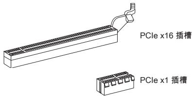
PCI (Peripheral Component Interconnect) 插槽
CMOS Setup Utility - Copyright (C) 1985-2005, American Megatrends, Inc.
Standard CMOS Features
Advanced BIOS Features
Integrated Peripherals
Power Management Setup
H/U Monitor
Green Power
BIOS Setting Password
Cell Menu
M-Flash
Overclocking Profile
Load Fail-Safe Defaults
Load Optimized Defaults
Save 8 Exit Setup
Exit Without Saving
1 Move Enter:Select / - / Value F0:Save ESC:Exit F1:General Help F4:CPU Spec F5:Memory-2 F0:Fall-Safe Defaults F6:Optimized Defaults
Configure Time and Date. Display System Information...
BIOS Version U1.0B5 CPU Frequency 2500MHz Physical Memory Size 204MB
Standard CMOS Features
Advanced BIOS Features
使用本選單設定特殊的進階功能。
Integrated Peripherals
使用本選單設定整合型週邊裝置。
Power Management Setup
使用本選單設定電源管理。
H/W Monitor
BIOS Setting Password
使用本選單設定BIOS密碼。
Cell Menu
本選單可指定頻率及電壓控制。
M-Flash
Overclocking Profile
Current CPU/ DRAM/ CPU-NB Frequency
CPU Technology Support
Adjust CPU FSB Frequency (MHz)
Start OC Stepping From (MHz)
Adjusted CPU Frequency (MHz)
本項顯示調整後CPU的頻率。唯讀。
Adjust CPU-NB Ratio
本項可調整CPU-NB倍頻比率。
Adjusted CPU-NB Frequency (MHz)
Adjusted Max Turbo Core Freq.
Adjusted Turbo Core Freq. (MHz)
Advanced Clock Calibration
Adjusted DRAM Frequency (MHz)
本項顯示調整後的記憶體頻率。唯讀。
HT Link Control
按下键進入子選單。
HT Incoming/Outgoing Link Width
Adjusted HT Link Frequency (MHz)
USB 3.0 (760GA-P43 (FX))
http://www.msi.com/service/cpu-support

CMOS Setup Utility - Copyright (C) 1985-2005, American Negatrends, Inc.
Standard CMOS Features
Advanced BIOS Features
Integrated Peripherals
Power Management Setup
H/U Monitor
Green Power
BIOS Setting Password
Cell Menu
M-Flash
Overclocking Profile
Load Fail-Safe Defaults
Load Optimized Defaults
Save 8 Exit Setup
Exit Without Saving
1 Move Enter:Select / - / Value F0:Save ESC:Exit F1:General Help F4:CPU Spec F5:Memory-2 F0:Fall-Safe Defaults F6:Optimized Defaults
Configure Time and Date. Display System Information...
BIOS Version U1.0B5 CPU Frequency 2500MHz Physical Memory Size 204MB
Standard CMOS Features (標準CMOS設定)
Integrated Peripherals (內藏機能の設定)
CPU Technology Support (CPUtek/口saboe-1)
CPU Feature (CPUの機能)
C1E Support (C1E\*s\*一卜)
Adjusted CPU Frequency (MHz) (調整たCPU周波数)
Unlock CPU Core (CPU□A为解除的)