
H67MAE35 - Motherboard MSI - Free user manual and instructions
Find the device manual for free H67MAE35 MSI in PDF.
| Product Type | Motherboard |
| Brand | MSI |
| Model | H67MAE35 |
| Form Factor | Micro-ATX (24.5 cm × 21.5 cm) |
| Dimensions | 24.5 cm × 21.5 cm |
| Approximate Weight | 0.5 kg |
| Required Power | ATX 24-pin connector + ATX 4-pin CPU |
| Supported Processors | Intel Core i7/i5/i3/Pentium/Celeron (LGA1155 socket) |
| Chipset | Intel H67 (B3) |
| Memory | 2 slots DDR3, up to 16 GB, DDR3 1333/1066, dual channel |
| Storage | 2× SATA 6 Gb/s, 4× SATA 3 Gb/s, RAID 0/1/5/10 |
| USB | 2× USB 3.0 (rear), 4× USB 2.0 (rear), internal USB 2.0 headers |
| Audio | Realtek ALC887, 8-channel HD |
| Network | Realtek RTL8111E Gigabit LAN |
| Display | HDMI, VGA, DVI-D (via integrated graphics processor) |
| Expansion Slots | 1× PCIe x16, 2× PCIe x1, 1× PCI |
| Maintenance | Clean with a soft dry cloth. Avoid moisture and chemicals. |
| Safety | Disconnect power before handling. Use an anti-static wrist strap. Do not short-circuit the board. |
| Spare Parts | Available on the MSI website (www.msi.com). |
| Repairability | Call a qualified technician. The board contains fragile components. |
Frequently Asked Questions - H67MAE35 MSI
User questions about H67MAE35 MSI
0 question about this device. Answer the ones you know or ask your own.
Ask a new question about this device
Download the instructions for your Motherboard in PDF format for free! Find your manual H67MAE35 - MSI and take your electronic device back in hand. On this page are published all the documents necessary for the use of your device. H67MAE35 by MSI.
USER MANUAL H67MAE35 MSI
The material in this document is the intellectual property of MICROSTARINTERNATIONAL. We take every care in the preparation of this document, but no guarantee is given as to the correctness of its contents. Our products are under continual improvement and we reserve the right to make changes without notice.
Trademarks
All trademarks are the properties of their respective owners.
MSI® is registered trademark of Micro-Star Int'l Co., Ltd.
NVIDIA® is registered trademark of NVIDIA Corporation.
ATI® is registered trademark of ATI Technologies, Inc.
AMD® is registered trademarks of AMD Corporation.
Intel® is registered trademarks of Intel Corporation.
Windows® is registered trademarks of Microsoft Corporation.
■ AMI® is registered trademark of American Megatrends, Inc.
Award® is a registered trademark of Phoenix Technologies Ltd.
Sound Blaster® is registered trademark of Creative Technology Ltd.
Realtek® is registered trademark of Realtek Semiconductor Corporation.
■ JMicron® is registered trademark of JMicron Technology Corporation.
Netware is a registered trademark of Novell, Inc.
Lucid is trademarks of LucidLogix Technologies, Ltd.
Revision History
| Revision | RevisionHistoryDate | Date |
| V2.4 Update | model name March 2011 | |
Technical Support
If a problem arises with your system and no solution can be obtained from the user's manual, please contact your place of purchase or local distributor. Alternatively, please try the following help resources for further guidance.
Visit the MSI website for technical guide, BIOS updates, driver updates, and other information: http://www.msi.com/service/download
Contact our technical staff at: http://support.msi.com
Safety Instructions
Always read the safety instructions carefully.
- Keep this User's Manual for future reference.
- Keep this equipment away from humidity.
- Lay this equipment on a reliable flat surface before setting it up.
- The openings on the enclosure are for air convection hence protects the equipment from overheating. DO NOT COVER THE OPENINGS.
Make sure the voltage of the power source is at 110/220V before connecting the equipment to the power inlet.
- Place the power cord such a way that people can not step on it. Do not place anything over the power cord.
Always Unplug the Power Cord before inserting any add-on card or module.
All cautions and warnings on the equipment should be noted.
- Never pour any liquid into the opening that can cause damage or cause electrical shock.
If any of the following situations arises, get the equipment checked by service personnel:
The power cord or plug is damaged.
Liquid has penetrated into the equipment.
The equipment has been exposed to moisture.
The equipment does not work well or you can not get it work according to User's Manual.
The equipment has been dropped and damaged.
The equipment has obvious sign of breakage.
DO NOT LEAVE THIS EQUIPMENT IN AN ENVIRONMENT ABOVE 60C (140°F), IT MAY DAMAGE THE EQUIPMENT.
CAUTION: There is a risk of explosion, if battery is incorrectly replaced.
Replace only with the same or equivalent type recommended by the manufacturer.
警告使用者:
For better environmental protection, waste batteries should be collected separately for recycling special disposal.
FCC-B Radio Frequency Interference Statement
This equipment has been tested and found to comply with the limits for a Class B digital device, pursuant to Part 15 of the FCC Rules. These limits are designed to provide reasonable protection against harmful inter

N1996
ference in a residential installation. This equipment generates, uses and can radiate radio frequency energy and, if not installed and used in accordance with the instructions, may cause harmful interference to radio communications. However, there is no guarantee that interference will not occur in a particular installation. If this equipment does cause harmful interference to radio or television reception, which can be determined by turning the equipment off and on, the user is encouraged to try to correct the interference by one or more of the measures listed below.
Reorient or relocate the receiving antenna.
Increase the separation between the equipment and receiver.
- Connect the equipment into an outlet on a circuit different from that to which the receiver is connected.
Consult the dealer or an experienced radio/television technician for help.
Notice 1
The changes or modifications not expressly approved by the party responsible for compliance could void the user's authority to operate the equipment.
Notice 2
Shielded interface cables and A.C. power cord, if any, must be used in order to comply with the emission limits.
VOIR LA NOTICE D'INSTALLATION AVANT DE RACCORDER AU RESEAU.

This device complies with Part 15 of the FCC Rules. Operation is subject to the following two conditions:
1) this device may not cause harmful interference, and
2) this device must accept any interference received, including interference that may cause undesired operation.
WEEE (Waste Electrical and Electronic Equipment) Statement
ENGLISH
To protect the global environment and as an environmentalist, MSI must remind you that...
Under the European Union ("EU") Directive on Waste Electrical and Electronic Equipment, Directive 2002/96/EC, which takes effect on August 13, 2005, products of "electrical and electronic equipment" cannot be discarded as municipal wastes anymore and manufacturers of covered electronic

equipment will be obligated to take back such products at the end of their useful life. MSI will comply with the product take back requirements at the end of life of MSI-branded products that are sold into the EU. You can return these products to local collection points.
DEUTSCH
FCC-B Radio Frequency Interference Statement.
WEEE (Waste Electrical and Electronic Equipment) Statement
English
Mainboard Specifications .En-2
Quick Components Guide .En-4
Screw Holes .En-5
CPU (Central Processing Unit) En-6
Memory En-10
Power Supply . . . . . . . . . . . . . . . . . . . . . . . . . . . . . . . . . . . . . . . . . . . . . . . . . . . . . . . .
Back Panel . En-13
Connectors . . . . . . . . . . . . . . . . . . . . . . . . . . . . . . . . . . . . . . . . . . . . . . . . . . . . . . . . . . .
Jumper. En-21
Slots .En-22
BIOS Setup . En-23
Software Information En-32
Deutsch
Mainboard Specifications
Processor Support
■ Intel® Core™ i7/ Core™ i5 /Core™ i3/ Pentium®/ Celeron® processor in the LGA1155 package (For the latest information about CPU, please visit http://www.msi.com/service/cpu-support)
Chipset
Intel®H67 (B3) chipset
Memory Support
2 DDR3 DIMMs support DDR3 1333/ 1066 DRAM (16GB Max)
Supports Dual-Channel mode (For more information on compatible components, please visit http://www.msi.com/service/test-report)
LAN
Supports LAN 10/100/1000 by Realtek® RTL8111E
Audio
HD audio codec integrated by Realtek® ALC887
- Flexible 8-channel audio with jack sensing
SATA
2 SATA 6Gb/s ports (SATA1~2) by Intel®H67 PCH
4 SATA 3Gb/s ports (SATA3~6) by Intel®H67 PCH
RAID
SATA1~6 support Intel® Matrix Storage Technology (AHCI/ RAID 0/ 1/ 5/ 10) by Intel® H67 PCH
USB 3.0 (H67MA-E35 (B3))
2 USB 3.0 rear IO ports by NEC D720200
Connectors
Back panel
- 1 PS/2 keyboard/ mouse combo port
- 2 USB 3.0 ports (H67MA-E35 (B3))
- 4 USB 2.0 ports
- 1 HDMI port* (H67MA-E35 (B3))
- 1 VGA port*
- 1 DVI-D port*
- 1 LAN port
- 6 flexible audio ports (H67MA-E35 (B3)) /
3 flexible audio ports (H67MS-E23 (B3))
*The HDMI, DVI-D and VGA ports only work with Integrated Graphics Processor)
On-Board
- 3 USB 2.0 connectors
- 1 Chassis Intrusion connector
- 1 S/PDIF-Out connector
- 1 Front Panel Audio connector
- 1 TPM Module connector
- 1 Parallel port connector
- 1 Serial port connector
Slots
1 PCIE x16 slot
2 PCIE x1 slots
1 PCI slot
Form Factor
Micro-ATX (24.5 cm × 21.5 cm)
Mounting
6 mounting holes
- If you need to purchase accessories and request the part numbers, you could search the product web page and find details on our web address http://www.msi.com/index.php
Quick Components Guide
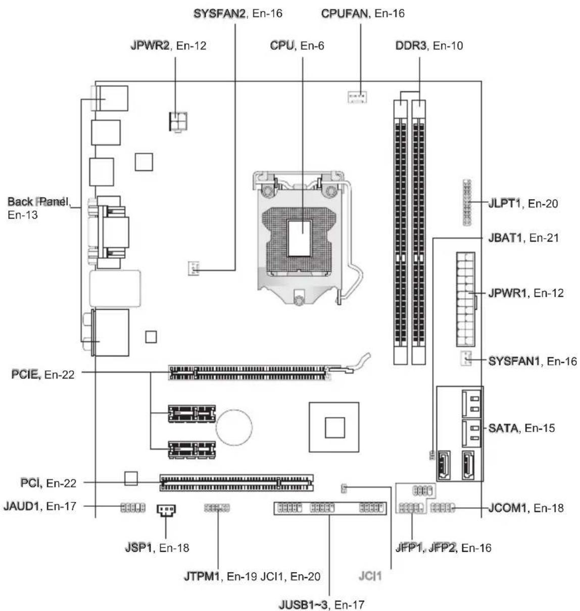
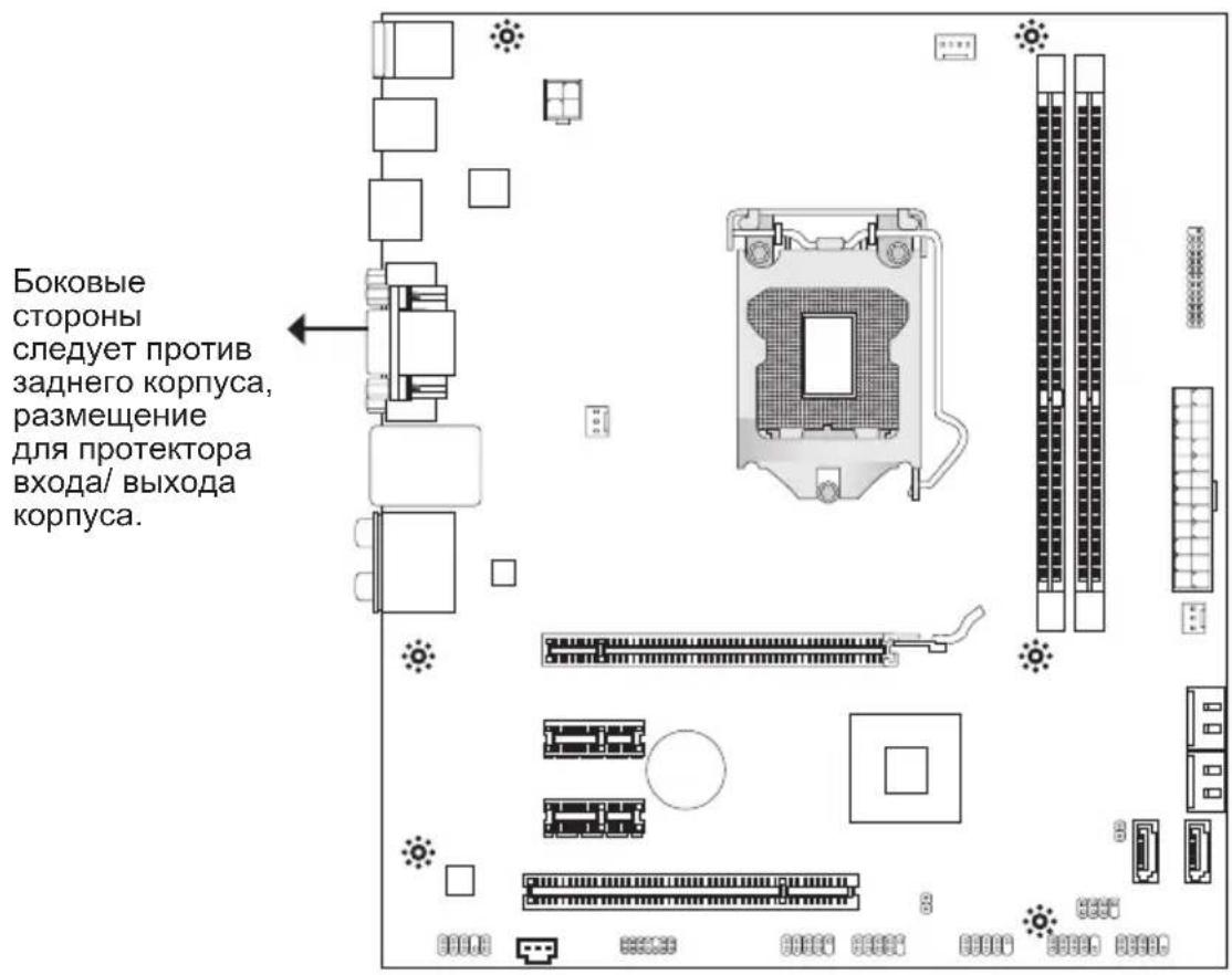
Screw Holes
When you install the mainboard, you have to place the mainboard into the chassis in the correct direction. The locations of screws holes on the mainboard are shown as below.

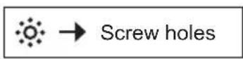
Refer above picture to install standoffs in the appropriate locations on chassis and then screw through the mainboard screw holes into the standoffs.
Important
- To prevent damage to the mainboard, any contact between the mainboard circuit and chassis or unnecessary standoffs mounted on the chassis is prohibited.
- Please make sure there are no metal components placed on the mainboard or within the chassis that may cause short circuit of the mainboard.
CPU (Central Processing Unit)
When you are installing the CPU, make sure to install the cooler to prevent overheating. If you do not have the CPU cooler, consult your dealer before turning on the computer. For the latest information about CPU, please visit http://www.msi.com/service/cpu-support
Important
Overheating
Overheating will seriously damage the CPU and system. Always make sure the cooling fan can work properly to protect the CPU from overheating. Make sure that you apply an even layer of thermal paste (or thermal tape) between the CPU and the heatsink to enhance heat dissipation.
Replacing the CPU
While replacing the CPU, always turn off the ATX power supply or unplug the power supply's power cord from the grounded outlet first to ensure the safety of CPU.
Overclocking
This mainboard is designed to support overclocking. However, please make sure your components are able to tolerate such abnormal setting, while doing overclocking. Any attempt to operate beyond product specifications is not recommended. We do not guarantee the damages or risks caused by inadequate operation or beyond product specifications.
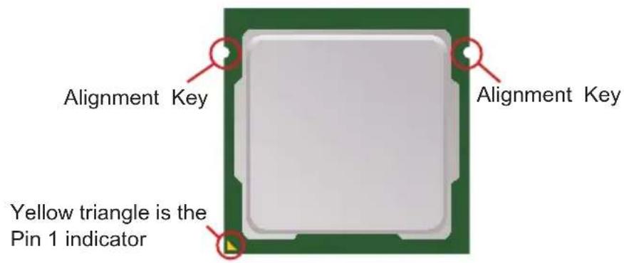
Introduction to LGA 1155 CPU
The surface of LGA 1155 CPU. Remember to apply some thermal paste on it for better heat dispersion.
CPU & Cooler Installation
When you are installing the CPU, make sure the CPU has a cooler attached on the top to prevent overheating. Meanwhile, do not forget to apply some thermal paste on CPU before installing the heat sink/cooler fan for better heat dispersion.
Follow the steps below to install the CPU & cooler correctly. Wrong installation will cause the damage of your CPU & mainboard.
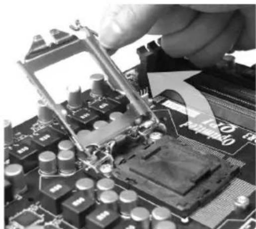
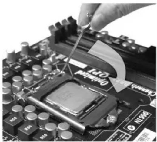
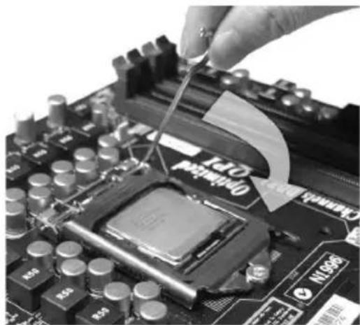
- Open the load level.
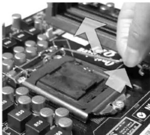
- Lift the load lever up to fully open position.
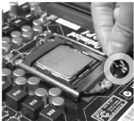
- After downloading the Pdualistication capcon it to protect the contact from damage. Before you install CPU, always cover it to protect the socket pin. Remove the cap (as the arrow shows).
4.
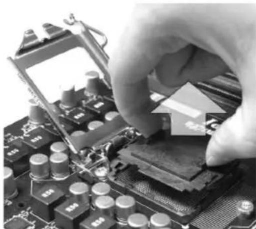
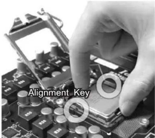
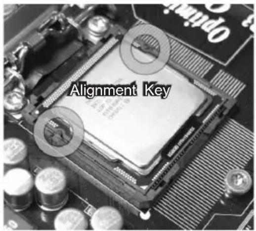
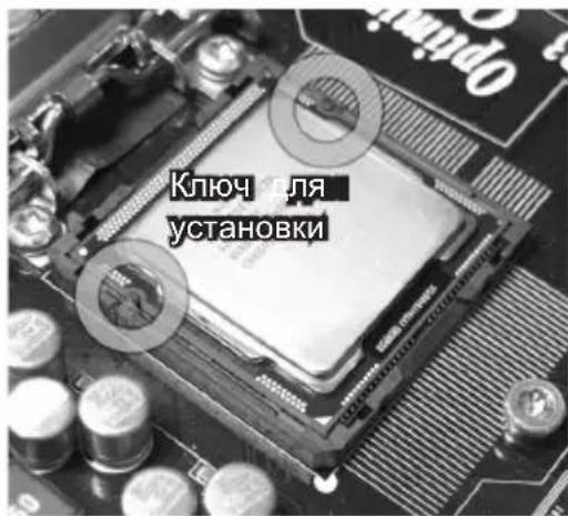
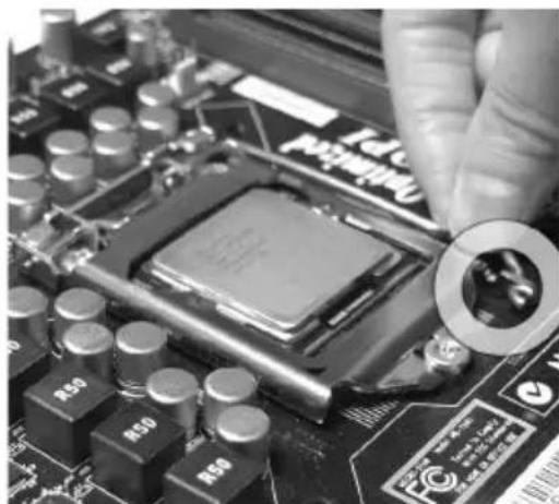
correct mating, put down the CPU in the socket housing frame. Be sure to grasp on the edge of the CPU base. Note that the alignment keys are matched.
- Visually inspect if the CPU is seated well into the socket. If not, take out the CPU with pure vertical motion and reinstall.
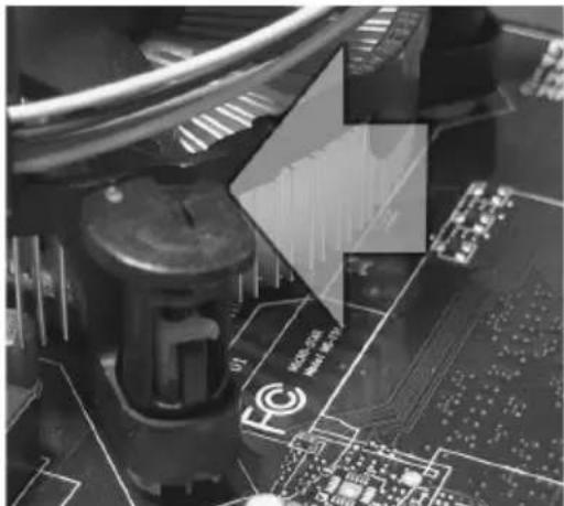
- Engage the load lever while pressing down lightly onto the load plate.
- M3eusrathteefourrheokstareokpand under the retention tab.
- per position before you install the cooler.
Important
- Confirm if your CPU cooler is firmly installed before turning on your system.
-
Do not touch the CPU socket pins to avoid damaging.
-
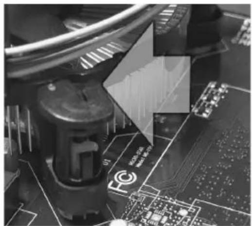
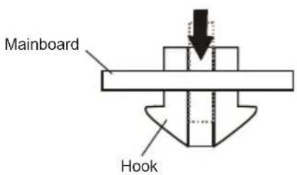
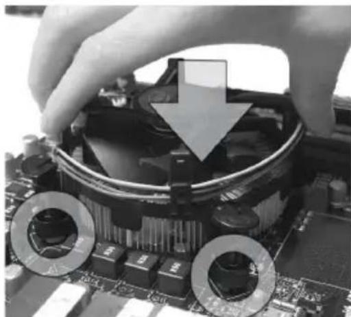
Preisgrithteefouleboekstokowraibofasterwith the heatsink. Push down the cooler until its four clips get wedged into the holes of the mainboard.
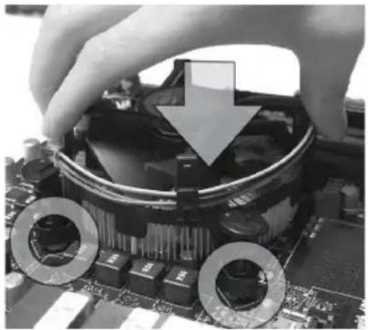
- Finently available theirOranato caotn that the clip-ends are correctly in-serted.
- the cooler.
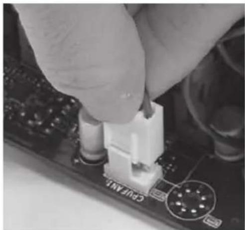
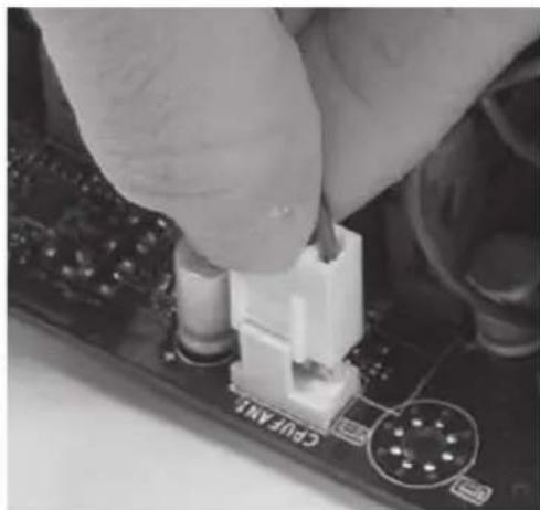
- the CPU fan connector on the mainboard.
Important
- Read the CPU status in BIOS.
- Whenever CPU is not installed, always protect your CPU socket pin with the plastic cap covered (shown in Figure 1) to avoid damaging.
- Mainboard photos shown in this section are for demonstration of the CPU/ cooler installation only. The appearance of your mainboard may vary depending on the model you purchase.
- Please refer to the documentation in the CPU fan package for more details about the CPU fan installation.
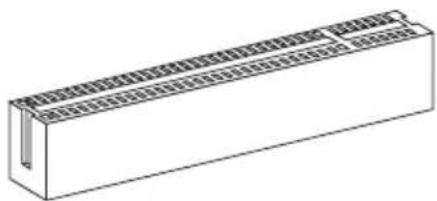
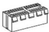
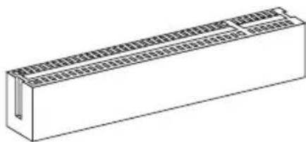
Memory
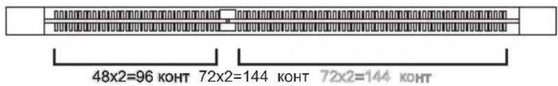
These DIMM slots are used for installing memory modules. For more information on compatible components, please visit http://www.msi.com/service/test-report
DDR3 240-pin,1.5V
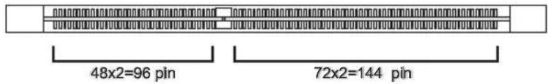
DIMM1 DIMM2
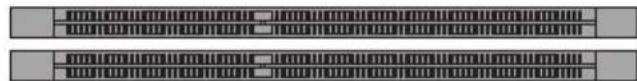
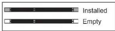
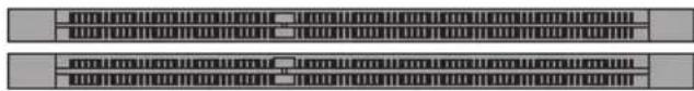
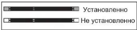
Dual-Channel mode Population Rule
In Dual-Channel mode, the memory modules can transmit and receive data with two data bus lines simultaneously. Enabling Dual-Channel mode can enhance the system performance. The following illustrations explain the population rules for Dual-Channel mode.
Important
- DDR3 memory modules are not interchangeable with DDR2, and the DDR3 standard is not backwards compatible. You should always install DDR3 memory modules in the DDR3 DIMM slots.
- In Dual-Channel mode, make sure that you install memory modules of the same type and density in different channel DIMM slots.
- Due to the chipset resource deployment, the system density will only be detected up to 15 + GB (not full 16GB) when each DIMM is installed with a 8GB memory module.
Installing Memory Modules
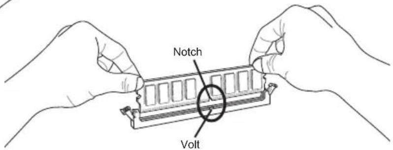
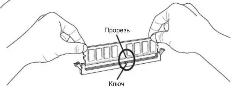
- The memory module has only one notch on the center and will only fit in the right orientation.
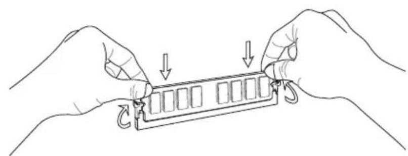
- Insert the memory module vertically into the DIMM slot. Then push it in until the golden finger on the memory module is deeply inserted in the DIMM slot. The plastic clip at each side of the DIMM slot will automatically close when the memory module is properly seated.
- Manually check if the memory module has been locked in place by the DIMM slot clips at the sides.

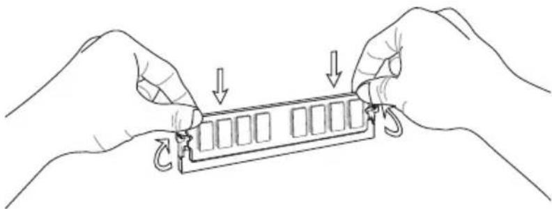
Important
You can barely see the golden finger if the memory module is properly inserted in the DIMM slot.
Power Supply
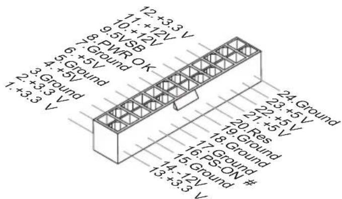
ATX 24-pin Power Connector: JPWR1
This connector allows you to connect an ATX 24-pin power supply. To connect the ATX 24-pin power supply, make sure the plug of the power supply is inserted in the proper orientation and the pins are aligned. Then push down the power supply firmly into the connector.
You may use the 20-pin ATX power supply as you like. If you'd like to use the 20-pin ATX power supply, please plug your power supply along with pin 1 & pin 13.

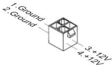
ATX 4-pin Power Connector: JPWR2
This connector is used to provide the power output to the CPU.
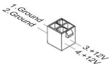
Important
Make sure that all the connectors are connected to proper ATX power supplies to ensure stable operation of the mainboard.
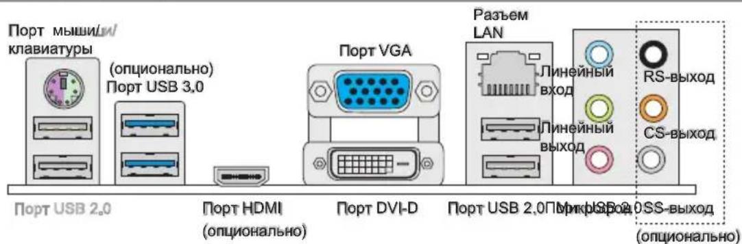
Back Panel
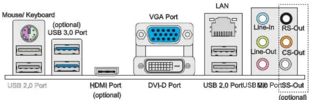
Mouse/Keyboard
The standard PS/2® mouse/keyboard DIN connector is for a PS/2® mouse/keyboard.
USB 2.0 Port
The USB 2.0 port is for attaching USB devices such as keyboard, mouse, or other USB-compatible devices.
USB 3.0 Port (optional)
USB 3.0 port is backward-compatible with USB 2.0 devices. Supports data transfer rate up to 5 Gbit/s (SuperSpeed).
Important
If you want to use a USB 3.0 device, you must use the USB 3.0 cable to connect to the USB 3.0 port.
HDMI Port (optional)
The High-Definition Multimedia Interface (HDMI) is an all-digital audio/video interface capable of transmitting uncompressed streams. HDMI supports all TV format, including standard, enhanced, or high-definition video, plus multi-channel digital audio on a single cable.
VGA Port
The DB15-pin female connector is provided for monitor.
DVI-D Port
The DVI-D (Digital Visual Interface - Digital) connector allows you to connect a LCD monitor. It provides a high-speed digital interconnection between the computer and its display device. To connect an LCD monitor, simply plug your monitor cable into the DVI-D connector, and make sure that the other end of the cable is properly connected to your monitor (refer to your monitor manual for more information.)
Important
The HDMI, VGA and DVI-D display interfaces on the mainboard are designed to serve as IGP (Integrated Graphics Processor) used. If you installed a processor without integrated graphics chip, these display ports will have no effect.
LAN
The standard RJ-45 LAN jack is for connection to the Local Area Network (LAN). You can connect a network cable to it.

| LED Color LED State Condition | |||
| Left Yellow Off LAN | LAN link is not established. | ||
| On(Steady state) LAN Link is established. | |||
| On(brighter & pulsing) The computer is communicating with another computer on the LAN. | |||
| Right Green Off 10 Mbit/sec data rate is selected. | |||
| On 100 Mbit/sec data rate is selected. | |||
| Orange On 1000 Mbit/sec data rate is selected. | |||
Audio Ports
These audio connectors are used for audio devices. It is easy to differentiate between audio effects according to the color of audio jacks.
Line-In: Blue - Line In, is used for external CD player, tape-player or other audio devices.
Line-Out: Green - Line Out, is a connector for speakers or headphones.
- Mic: Pink - Mic, is a connector for microphones.
RS-Out (optional): Black - Rear-Surround Out in 4/5.1/7.1 channel mode.
CS-Out (optional): Orange - Center/ Subwoofer Out in 5.1/7.1 channel mode.
SS-Out (optional): Gray - Side-Surround Out 7.1 channel mode.
Important
If the mainboard, which equips 3 audio jacks, wants to reach the 8-channel sound effect, the 7th and 8th channels must be output from front panel.
Connectors
Serial ATA Connector: SATA1~6
This connector is a high-speed Serial ATA interface port. Each connector can connect to one Serial ATA device.
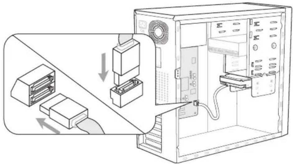
* The MB layout in this figure is for reference only.
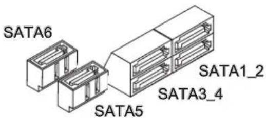
SATA1~2 (6Gb/s)
SATA3~6 (3Gb/s)
Important
Please do not fold the Serial ATA cable into a 90-degree angle. Otherwise, data loss may occur during transmission.
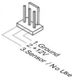
Fan Power Connectors: CPUFAN,SYSFAN1~2
The fan power connectors support system cooling fan with +12V . When connecting the wire to the connectors, always note that the red wire is the positive and should be connected to the +12V ; the black wire is Ground and should be connected to GND. If the mainboard has a System Hardware Monitor chipset on-board, you must use a specially designed fan with speed sensor to take advantage of the CPU fan control.
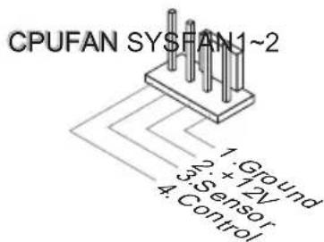
SYSFAN1-2
Important
- Please refer to the recommended CPU fans at processor's official website or consult the vendors for proper CPU cooling fan.
- CPUFAN support Smart fan control. You can install Control Center utility that will automatically control the CPUFAN speeds according to the actual CPUFAN temperatures.
Fan cooler set with 3 or 4 pins power connector are both available for CPUFAN.
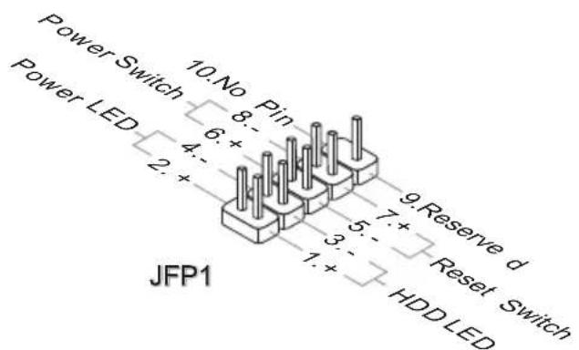
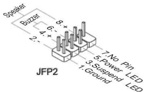
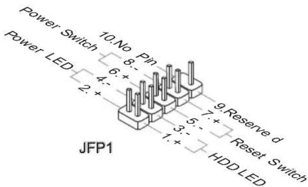
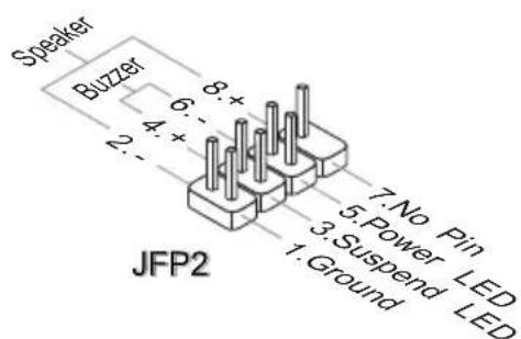
Front Panel Connectors: JFP1, JFP2
These connectors are for electrical connection to the front panel switches and LEDs. The JFP1 is compliant with Intel® Front Panel I/O Connectivity Design Guide.
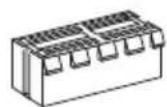
Front USB Connector: JUSB1~3
This connector, compliant with Intel® I/O Connectivity Design Guide, is ideal for connecting high-speed USB interface peripherals such as USB HDD, digital cameras, MP3 players, printers, modems and the like.
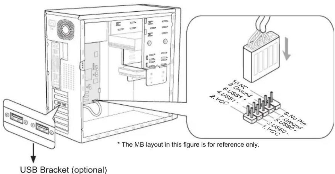
Important
Note that the pins of VCC and GND must be connected correctly to avoid possible damage.
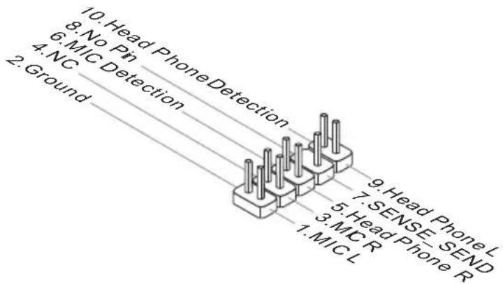
Front Panel Audio Connector: JAUD1
This connector allows you to connect the front panel audio and is compliant with Intel® Front Panel I/O Connectivity Design Guide.

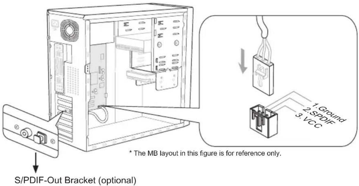
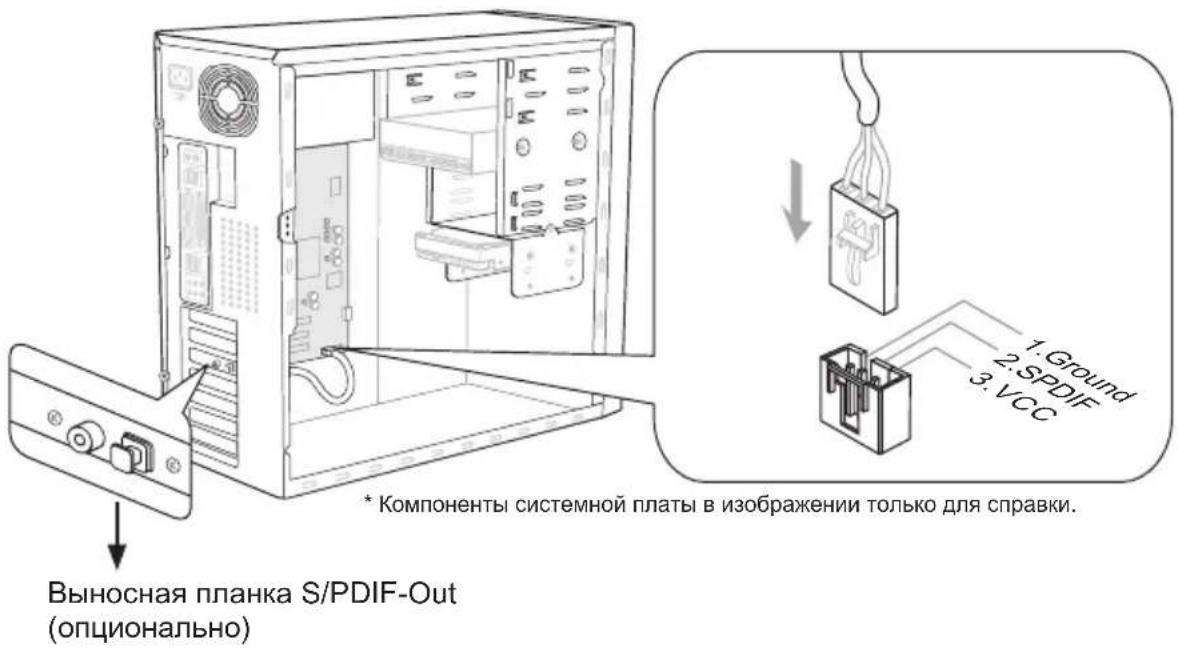
S/PDIF-Out Connector: JSP1
This connector is used to connect S/PDIF (Sony & Philips Digital Interconnect Format) interface for digital audio transmission.
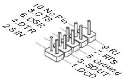
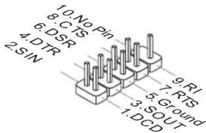
Serial Port Connector: JCOM1
This connector is a 16550A high speed communication port that sends/receives 16 bytes FIFOs. You can attach a serial device.
TPM Module connector: JTPM1
This connector connects to a TPM (Trusted Platform Module) module (optional). Please refer to the TPM security platform manual for more details and usages.

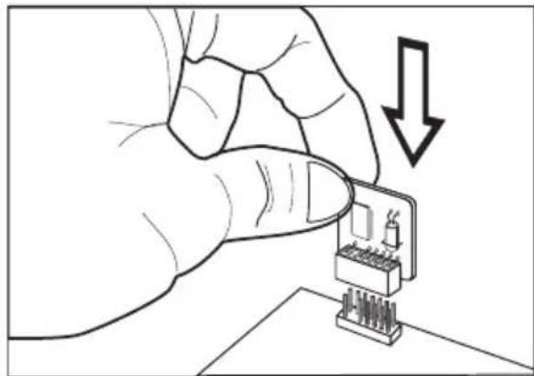
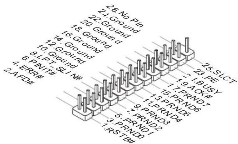
Parallel Port Connector: JLPT1
This connector is used to connect an optional parallel port bracket. The parallel port is a standard printer port that supports Enhanced Parallel Port (EPP) and Extended Capabilities Parallel Port (ECP) mode.
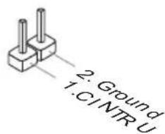
Chassis Intrusion Connector: JCI1
This connector connects to the chassis intrusion switch cable. If the chassis is opened, the chassis intrusion mechanism will be activated. The system will record this status and show a warning message on the screen. To clear the warning, you must enter the BIOS utility and clear the record.
Jumper
Clear CMOS Jumper:JBAT1
There is a CMOS RAM on board with an external battery power supply to preserve the system configuration data. With the CMOS RAM, the system can automatically boot OS every time it is turned on. If you want to clear the system configuration, please temporarily short these two pins to clear data by using a metal object.

Keep Data Clear Data

(Use a metal object to temporarily short these two pins.)
Important
You can clear CMOS by touching two pins once with a metal object while the system is off. Avoid clearing the CMOS while the system is on; it will damage the mainboard.
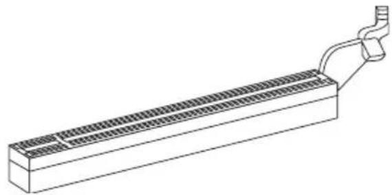
Slots
PCIE (Peripheral Component Interconnect Express) Slot
The PCIE slot supports the PCIE interface expansion card.
PCIE x16 Slot
PCIE x1 Slot
PCI (Peripheral Component Interconnect) Slot
The PCI slot supports LAN card, SCSI card, USB card, and other add-on cards that comply with PCI specifications.
32-bit PCI Slot
Important
When adding or removing expansion cards, make sure that you unplug the power supply first. Read the documentation for the expansion card to configure any necessary hardware or software settings, such as jumpers, switches or BIOS configuration.
PCI Interrupt Request Routing
IRQ, or interrupt request line, are hardware lines over which devices can send interrupt signals to the microprocessor. The PCI IRQ pins are typically connected to the PCI bus pins as follows:
| Order1 Order2 Order3 Order4 Order4 | |
| PCI Slot INT | A# INT B# INT C# INT D# |
BIOS Setup
This chapter provides basic information on the BIOS Setup program and allows you to configure the system for optimum use. You may need to run the Setup program when:
An error message appears on the screen during the system booting up, and requests you to run BIOS SETUP.
- You want to change the default settings for customized features.
Important
- The items under each BIOS category described in this chapter are under continuous update for better system performance. Therefore, the description may be slightly different from the latest BIOS and should be held for reference only.
- Upon boot-up, the 1st line appearing after the memory count is the BIOS version. It is usually in the format:
E7680IMS.xxx 010611 where:
1st digit refers to BIOS type as E = EFI
2nd - 5th digit refers to the model number.
6th digit refers to the chipset as I = Intel, N = n Vidia, A = AMD and V = VIA .
7th - 8th digit refers to the customer as MS = all standard customers.
xxx refers to the BIOS version.
010611 refers to the date this BIOS was released.
Entering Setup
Power on the computer and the system will start POST (Power On Self Test) process. When the message below appears on the screen, press key to enter Setup.
Press DEL to enter Setup Menu, F11 to enter Boot Menu
If the message disappears before you respond and you still wish to enter Setup, restart the system by turning it OFF and On or pressing the RESET button. You may also restart the system by simultaneously pressing <Ctrl> , <Alt> , and <Delete> keys.
Control Keys
| <↑><↓> Select Item |
| <←><→> Select Screen |
| <Enter> Select |
| <Esc> Jumps to the Exit menu or returns to the main menu from a submenu |
| <++<-> Change Option |
| <F1> General Help |
| <F6> Load Optimized Defaults |
| <F10> Save all the CMOS changes and exit |
Getting Help
After entering the Setup menu, the first menu you will see is the Main Menu.
Main Menu
The main menu lists the setup functions you can make changes to. You can use the arrow keys (↑↓) to select the item. The on-line description of the highlighted setup function is displayed at the bottom of the screen.
Sub-Menu
If you find a right pointer symbol (as shown in the right view) appears to the left of certain fields that means a sub-menu can be launched from this field. A sub-menu contains additional options for a field parameter. You can use arrow keys ( ) to highlight the field and press
General Help
The BIOS setup program provides a General Help screen. You can call up this screen from any menu by simply pressing <F1>. The Help screen lists the appropriate keys to use and the possible selections for the highlighted item. Press <Esc> to exit the Help screen.
The Menu Bar
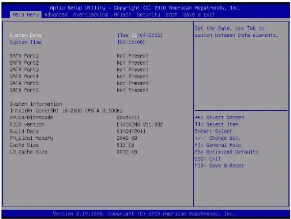
Main Menu
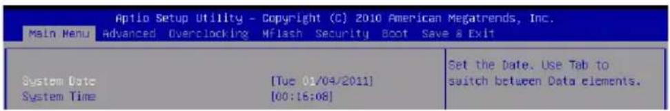
Use this menu for basic system configurations, such as time, date etc.
Advanced
Use this menu to setup the items of the BIOS special enhanced features, integrated peripherals, power management and PC health status.
Overclocking
Use this menu to specify your settings for frequency/voltage control and overclocking.
Mflash
Use this menu to read/ flash the BIOS from storage drive (FAT/ FAT32 format only).
Security
Use this menu to set supervisor and user passwords.
Boot
Use this menu to specify the priority of boot devices.
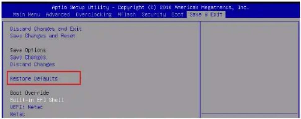
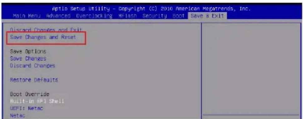
Save & Exit
This menu allows you to load the BIOS default values or factory default settings into the BIOS and exit the BIOS setup utility with or without changes.
When enter the BIOS Setup utility, follow the processes below for general use.
- Load Optimized Defaults: Use the arrow keys (, , , ) to select the [Restore Defaults] in [Save & Exit] menu, and press
. A pop-up message will appear, please select [Yes] and press to load the default settings for optimal system performance.
- Setup Date/ Time: Use the arrow keys (, , , ) to select the [System Date]/[System Time] in [Main Menu] menu, and press
. And then, you can set the Date, Time in their respective fields.
- Save & Exit Setup: Use the arrow keys (, , , ) to select the [Save Changes & Reset] in [Save & Exit] menu, and press
. A pop-up message will appear, please select [Yes] and press to save the configurations and exit BIOS setup utility.
Overclocking
This menu is for advanced user who want to overclock the mainboard.
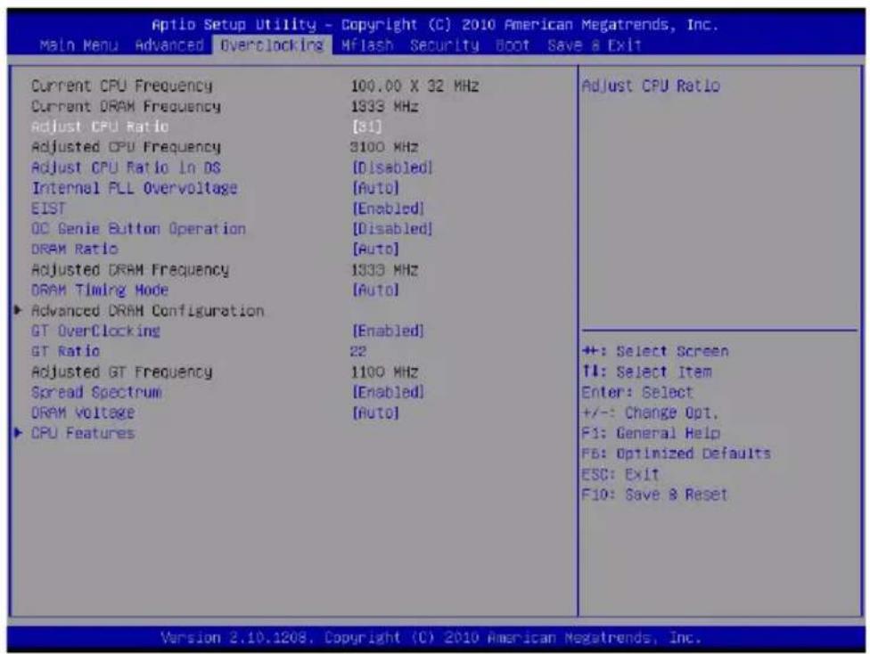
Current CPU / DRAM Frequency
These items show the current clocks of CPU and Memory speed. Read-only.
Adjust CPU Ratio
This item controls the multiplier that is used to determine the internal clock speed of the processor relative to the external or motherboard clock speed. It is available only when the processor supports this function.
Adjusted CPU Frequency
It shows the adjusted CPU frequency. Read-only.
Adjust CPU Ratio in OS
Enable this item, it will allow you to change the CPU ratio in OS by using MSI application.
Internal PLL Overvoltage
This item are used to adjust the PLL voltage.
EIST
The Enhanced Intel SpeedStep technology allows you to set the performance level of the microprocessor whether the computer is running on battery or AC power. This field will appear after you installed the CPU which supports speedstep technology.
OC Genie Button Operation
This field is used to enable/ disable OC Genie function.
DRAM Ratio
This setting controls the ratio of memory frequency to enable the memory to run at different frequency combinations.
Adjusted DRAM Frequency
It shows the adjusted DRAM frequency. Read-only.
DRAM Timing Mode
Select whether DRAM timing is controlled by the SPD (Serial Presence Detect) EEPROM on the DRAM module. Setting to [Auto] enables DRAM timings and the following "Advanced DRAM Configuration" sub-menu to be determined by BIOS based on the configurations on the SPD. Selecting [Link] or [Unlink] allows users to configure the DRAM timings and the following related "Advanced DRAM Configuration" sub-menu manually.
Advanced DRAM Configuration
Press
Command Rate
This setting controls the DRAM command rate.
tCL
This controls the CAS latency, which determines the timing delay (in clock cycles) before SDRAM starts a read command after receiving it.
tRCD
When DRAM is refreshed, both rows and columns are addressed separately. This setup item allows you to determine the timing of the transition from RAS (row address strobe) to CAS (column address strobe). The less the clock cycles, the faster the DRAM performance.
tRP
This setting controls the number of cycles for Row Address Strobe (RAS) to be allowed to precharge. If insufficient time is allowed for the RAS to accumulate its charge before DRAM refresh, refreshing may be incomplete and DRAM may fail to retain data. This item applies only when synchronous DRAM is installed in the system.
tRAS
This setting determines the time RAS takes to read from and write to memory cell.
tRFC
This setting determines the time RFC takes to read from and write to a memory cell.
tWR
Minimum time interval between end of write data burst and the start of a precharge command. Allows sense amplifiers to restore data to cells.
→tWTR
Minimum time interval between the end of write data burst and the start of a column-read command. It allows I/O gating to overdrive sense amplifiers before read command starts.
TRRD
Specifies the active-to-active delay of different banks.
tRTP
Time interval between a read and a precharge command.
tFAW
This item is used to set the tFAW (four activate window delay) timing.
tWCL
This item is used to set the tWCL (Write CAS Latency) timing.
tCKE
This item is used to set the tCKE timing.
tRTL
This item is used to set the tRTL timing.
Advanced Channel 1/2 Timing Configuration
Press
GT OverClocking
This item allows you to enable/ disable the overclocking of integrated graphics.
GT Ratio
This setting controls the ratio of integrated graphics frequency to enable the integrated graphics to run at different frequency combinations.
Adjusted GT Frequency
It shows the adjusted integrated graphics frequency. Read-only.
Spread Spectrum
When the mainboard's clock generator pulses, the extreme values (spikes) of the pulses create EMI (Electromagnetic Interference). The Spread Spectrum function reduces the EMI generated by modulating the pulses so that the spikes of the pulses are reduced to flatter curves.
Important
- If you do not have any EMI problem, leave the setting at [Disabled] for optimal system stability and performance. But if you are plagued by EMI, select the value of Spread Spectrum for EMI reduction.
- The greater the Spread Spectrum value is, the greater the EMI is reduced, and the system will become less stable. For the most suitable Spread Spectrum value, please consult your local EMI regulation.
- Remember to disable Spread Spectrum if you are overclocking because even a slight jitter can introduce a temporary boost in clock speed which may just cause your overclocked processor to lock up.
DRAM Voltage
This item is used to adjust the memory voltage.
CPU Features
Press
Hyper-threading
The processor uses Hyper-Threading technology to increase transaction rates and reduces end-user response times. The technology treats the two cores inside the processor as two logical processors that can execute instructions simultaneously. In this way, the system performance is highly improved. If you disable the function, the processor will use only one core to execute the instructions. Please disable this item if your operating system doesn't support HT Function, or unreliability and instability may occur.
Important
Enabling the functionality of Hyper-Threading Technology for your computer system requires ALL of the following platform Components:
CPU: An Intel® Processor with HT Technology;
- Chipset: An Intel® Chipset that supports HT Technology;
BIOS: A BIOS that supports HT Technology and has it enabled;
- OS: An operating system that supports HT Technology.
For more information on Hyper-threading Technology, go to:
www.intel.com/info/hyperthreading
Active Processor Cores
This item allows you to select the number of active processor cores.
Limit CPUID Maximum
It is designed to limit the listed speed of the processor to older operating systems.
Execute Disable Bit
Intel's Execute Disable Bit functionality can prevent certain classes of malicious "buffer overflow" attacks when combined with a supporting operating system. This functionality allows the processor to classify areas in memory by where application code can execute and where it cannot. When a malicious worm attempts to insert code in the buffer, the processor disables code execution, preventing damage or worm propagation.
Intel Virtualization Tech
This item is used to enable/disable the Intel Virtualization technology. For further information please refer to Intel's official website.
Power Technology
This item allows you to select the Intel Dynamic Power technology mode.
C1E Support
To enable this item to read the CPU power consumption while idle. Not all processors support Enhanced Halt state (C1E).
OverSpeed Protection
Overspeed Protection function can monitor the current CPU draws as well as its power consumption. If it exceeds a certain level, the processor automatically reduces its clock speed. If you want to overclock your CPU, set it to [Disabled].
Intel C-State
C-state is a power management state that significantly reduces the power of the processor during idle. This field will appear after you installed the CPU which supports c-state technology.
Package C-State limit
This field allows you to select a C-state limit.
> Long duration power limit(W)
This field allows you to adjust the TDP power limit for the long duration.
Long duration maintained(ms)
This field allows you to adjust the maintaining time for long duration power limit.
Short duration power limit(W)
This field allows you to adjust the TDP power limit for the short duration.
Primary/ Secondary plane turbo power limit (W)
These fields allow you to adjust the TDP limit for the primary/ secondary plane turbo.
Software Information
Take out the Driver/Utility DVD that is included in the mainboard package, and place it into the DVD-ROM drive. The installation will auto-run, simply click the driver or utility and follow the pop-up screen to complete the installation. The Driver/Utility DVD contains the:
- Driver menu : It provides available drivers. Install the driver by your desire and to activate the device.
- Utility menu : It allows you to install the available software applications.
- Service base menu : Through this menu to link the MSI officially website.
- Product info menu : It shows the newly information of MSI product.
- Security menu : It provides the useful antivirus program.
Important
Please visit the MSI officially website to get the latest drivers and BIOS for better system performance.

Deutsch
H67MA-E35 (B3)/
H67MS-E23 (B3)
Serie
Spezifikationen
Prozessoren
The DB15-pin female connector is provided for monitor.
DVI-D Anschluss
Current CPU / DRAM Frequency
Adjusted CPU Frequency
Adjust CPU Ratio in OS
Adjusted DRAM Frequency
Advanced Channel 1/2 Timing Configuration
Adjusted GT Frequency
Active Processor Cores
Intel Virtualization Tech
OverSpeed Protection
Package C-State limit
> Long duration maintained(ms)
Primary/ Secondary plane turbo power limit (W)
http://www.msi.com/service/cpu-support
Important
Surchauffe
Emplacement PCIE (Peripheral Component Interconnect Express)
Emplacement PCI (Peripheral Component Interconnect)
Current CPU / DRAM Frequency
Adjusted CPU Frequency
Adjust CPU Ratio in OS
OC Genie Button Operation
Adjusted DRAM Frequency
Advanced Channel 1/2 Timing Configuration
Adjusted GT Frequency
Active Processor Cores
Intel Virtualization Tech
OverSpeed Protection
Package C-State limit
> Long duration maintained(ms)
Primary/ Secondary plane turbo power limit (W)
*IopHDMI, DVI-D n VGA pa6oTaHT oTbko B npoucecope Integrated Graphics Processor)
Pa3bembl, yctaHOBnEHHbIe Ha nlaTe
- 3 pa3bema USB 2.0
- 1 pa3bem DaTUnKa OTKpbIBaHn KOpnyca
- 1 pa3bem S/PDIF-Out
- 1 pa3bem Дя подклюеця aydno Ha nepeDne naneHn
- 1 pa3bem TPM Moyny
-1pa3bemnapaannenbHoro npota
-1pa3bem nocneIOBaTeNbHoro npTa
CNOTbl
1 cnot PCIE x16
2 cnoTa PCIE x1
1 cnot PCI
ΦopM ΦakTop
Micro-ATX (24.5 cm × 21.5 cm)
Kpenenne
6 OTBepctn IJIa KpeIeHna
* POMOuB B INPNO6peTeHnI DOnONHInTeNbHbIX akceccyapOB I NOnCKe HOMepa N3dJIINM OMOHnHaHTn No aDpecy http://www.msi.com/index.php
Pa3MeueHHe KOMnoHETOB CnCTeMHoI PnAToB

OTBepCTnIy BnHTOB
Ipn yctaHOBKe cnCTeMHo INaTbI HxKHO BCTaBnTb eB B KopnyC B npaBnBHom HnnpaBHeHH. Pa3MeueHnA OTBepCTn dJa BNHTOB NOKa3aHbI HnKe.

CneyuTe yka3aHnM BblIe yka3aHHo DJIyCTaHOBKn DEpKaTeJIeB IpaBnIbHOM MeTe B KOpnyCe N 3aTeM BBHTNTe BNHTbI Yepe3 OTBepCTNJa DNRA BNHTOB B DEpKaTeJI.
BhimaHne
- Bo n36exaHne noBpeJdeHn K CnCTeMHo Npate, IIObO KoHTaKT MeXy npOBokamn CnCTeMHo N pAtbl N Kopnycom NJI Hno6BaTeJbHbN DePkaTeJb yCTaHOBneH B Kopnyce 3anpeuH.
- YbEHTecB TOM, yTO Ha CNTeMHoN Pnate Nn B KOpnyce HeT HnKaKOro MetaJIuYeCKOrO KOMNoHEnTa, KOtOpbIMoXeT Bbl3BaTb 3aKOpaUnBaHne CNTeMHoN Pnate.
CPU (LêntpaJIbHbI npoceccop)
Ipn yctaHOBKe CPU, yTo6bl y6epey npoecccop ot neperpBe, He 3abyte yCTaHOBnTb npoecccopHbKuIep. Ecnn y Bac HET npoecccopHoro KUJIepa, noXaanyIcTa, CBJNTeCb C dInlepOM C ueIbIO npno6peTeHn I erO yCTaHOBKn Do TOrO, KaK BKJIouHITe KOMNbIoTeP.
Последно Информацио о подержke поз ECCOPOB можно пolyntь на сат http://www.msi.com/service/cpu-support
Bhimahine
Iepepe
IpepeB moKet cepb3HO NOBpeNTb CEHTpaJIbHbI pOucecop. YTo6bl yBepey npoueccop ot neperpeBa, yBeiTEcB B TOM, yTO pOuceccopHbI KJnep paBoTaET HopMaIbHo. IInyUyuHnA TENNOOTBOH HeOBxODmO HaHeCTn CNoT EINPONpOBOJaSe nactbl (IIIn TENNONPOBOJaSe JENTbl) MeKdy pOucecopOM n padNaTopom.
3aMeHa CPU
Pn 3ame He CPU, BO n36eXaHne ero nobpeXdEHH, oBraTeIbHO OTKnIOHTe NCTOHTNK nTahn nn BbHbTe BNkY 6noka nTahn nn p03ETK.
Pa3roH
3Ta cnCTeMHna nIATA NOdepKnBaet "pa3roH". Y6eINTEcB, YTO KOMNOHeTb CnCTeMb cNoocbHb pa6oTaB b TaKnx HeCTaHdapTHbIX peKImax npu pa3roHe. He peKomeHdyetc HcNoJIb3OBAb TpoNyKT B peKImax, He COOTBeTCTByIOxuYka3aHHbIM B CneUΦNkauX. Mbl He rapaHTnpyem 3aunTy OT NOBpeKdEHN u pCKOB, Bbl3BaHHbIX HENpaBUNbHOJ 3KcIIpyataune N yCTaHOBKOJ napameTpOB C npEbbIweHEm XapaKTePncTtK.
YcTaHOBKa npoueccopa LGA 1155
BHeuHn BvI npouecoppa. UTo6bl yBeJIuHTb TeNlOpaccenBaHne, y6eINTeCb B TOM, UTO HaHecen CNoI TeNlONpOBoDAJuei nactbl.
Knou dny yctaHOBKn
KjntbI TpeyrolbHnK
YBnETCR
HnDnKaTOPOM 1 KOHT.
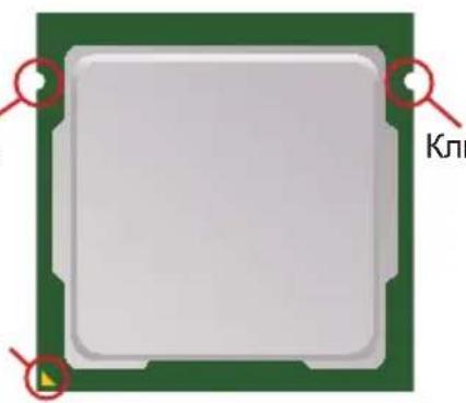
Klouy dlya yctaHOBKn
YcTaHOBka npoueccopa n BeHTnIaTopa
Bo n36exhaHnepepeBa npn pa6ote o6raTeIbHO yCTaHOBtE BeHTNlTOp npoueCCopa OndOBpemehno, yTO6bl yIyUHTb TEPNOOTBOID, y6eINTecb B TOM, yTO HaHeCen CIOI TEPNONPOBDAuJe nactbl Ha npoueCCope nepey cTAHOBKO BEHTNlTOpa.
CneNyIte daHbIM yka3aHnM nI npabInbHOY yCTaHOBKn. HenpaBnBHaY cTaHOBKa npNBedeT K NOBpeXdeHnO pOueccopa N CNTeMHo NnAToI.
- NotaHnte 3a pbuar kpenJIeHnI.
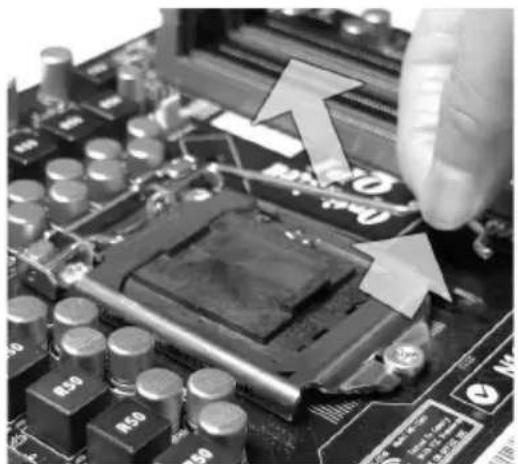
- YOeHMMIOPOueOBopa 4pHbHOI nlaCTNKOBON KpbIshKO, KOtOpA 3aunuaeT KOHTAKBpa3beMa OT NOBpeKdEHN. Pn OTCyTCTBnN npoecccopa, Heo6xOIMMO BcERda 3aKpbIBaTB pa3bem NlactNKOBON KpbIshKO IJRA 3aunrBoIero KOHTAKTOB. ChmMTe KpbIshKy (kak NOKa3bIBaET cTpeNka).
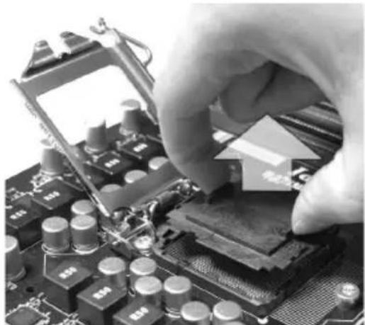
2.ПОДнIMTe pIyar n OTKpoIte MeTaNIIuYeCKyO KpbIuKy dIpyCTaHOBKn IPOUeCCopa.

- opneHTaun npoeccopa, noJoxte npoecop B pa3bem. 06paTte BHMaHne, yTO BbiEMKn Ha npoeccope DoJxHbI COOTBETCTBOBaTb BBICTyNam Ha npoecccophom pa3beme.

- Bn3yaJIbHo npOBepbTe npaBnIbHOcTb yCTaHOBKn npOeCCopa B pa3beM. Ecnn npoeccop yCTaHOBneH HenpaBnIbHO, TO BBInbTe npoecccop n nepeyctaHOBNTe.
- Onyctnte MetaJIINueckyIO KpbIuKy MexaHn3Ma KpePnneHnA.
- ΠepyTcBaaHbKaHn HaeKpbNkypa MexAH3Ma KpenJIeHn I 3aФNKcPyIte erO.
- y6eIntecb, YTO BCE yeTbipe 3aueJKN npabNlbo CopneHTnpoBaHbl.
BhimaHne
- PpeBnIOueHnEM CNTEmbI y6eIITecb, YTO BEHTINrTOp npabUNbHO yCTaHOJIeN.
Bo n3bexkHne noBpeKdEHH He npukacaiTecb K KOHTaKtAm COKeTa npouceccopa.
9.HaMeETHeeYETBepCTAeHemHOI PnAtbIC3aUeKAMN KpePNeHnBEHTnIaTopa.PnJxMITEpaNaTOp CBeHTnIaTOpOM K npOceCCopy INpocneIte, YTObIyTeTbIpe 3aUeKNBOuIN B OTBepCTnI cNCTeMHoI PnAtbl.
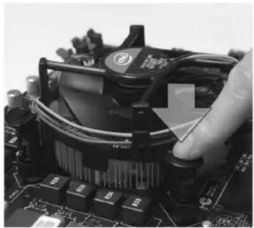
- 3aKpeNITe BeHTnIaTOp.
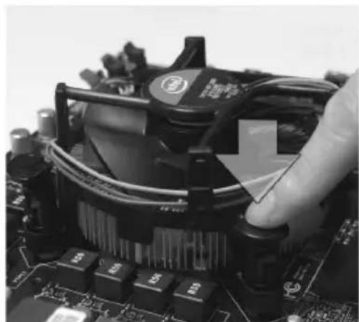
- BeHTnIaTopa CPU K pa3bemy Ha cnCTeMHoI nIaTe.
Bhimahine
- UHΦopMaunio 6b yctaHOBJeHHOM npouceCope CMOTpuTe B BIOS.
- Ecnn npouecccop He yctaHOBnE, Bcerda 3akpbBaIte pa3bem nlaCTNKOB0 KpbIuKoJ IJI npedOTBpaueHn NOLOMOK N nonadaHn B Hero rpr3n n nbIIN. (CMOTpTe yka3aHne 1).
ΦOTO CNTeMHOn nIaTbI, pa3MeUeHHbI e B 3ToI qACTn, npNBedeHbI TOIbKO dIg DEMOHCTpaUyCTaHOBKn BEHTUNrTopa. ObuN BnD CNTeMHOn nIaTbI 3aBNCIT OT MOnEJI, KYNJIeHHoB BamN.
3a dononHntbHn HhOpMaueNe 06 yctAHOBKe BEHTNlAToPA npoeccca o6paNTeCb K DOkyMeHTaun B ynaKOBKe BEHTNlAToPA npoeccca.
PamrTb
CnotbIMDIMNcnoB3yOTcIyraHObKMOdyneIamrTn.3aDOnONHHTeHBHO HOpMaueNeO COBmectmbix KOMNOHeHTax o6paTntecb Ha caNT http://www.msi.com/service/test-report
DDR3
240-KoHT,1.5V
Ppabnla yctaHOBKn MOynei namrtn dpr pa60tbI B
DByXkHaJIbHOMpeKIMe
B DByXkHaHbHom pexKIme MoDyHn NaMrtu Mory T nepeDaBaT b npHmAtb DaHHbIe no 2 uHAm oDHOBeMeHHo. Pn nCNoJIb3OBAHm NByXkHaHbHoro peXkMa npOn3BOdntelbHOCTb CnCTeMbI NOBbIaETc. Hxke npNBedeHb IpaBnla 3anONHeHn cNOTOB naMRTn dJa pa6ToB b DByXkHaHbHom pexKIme.
DIMM1
DIMM2
BhIMaHnE
- Moулн DDR3 He B3aHMo3aMeHЯeMbI C MoулЯMn DDR2, И стандг T DDR3 He Imeetобразно coBmecTmoocTn. CneIyET BceIg a yCTaHabJIbBaTb Moулп namrTn DDR3Вpa3bembl DDR3 DIMM.
-Дя pa6Otbl B DByXkaHaJIbHOM pexime y6eIITecb,уTO B pa3beMax pa3HbIX kaHaIOB y Bac yCTaHOBJIeHbI MOdyIIM OJHOro TnIa N OJINHAKOBOE MKOCTN. - 13-3a cneuФnpu paCnpedeneHna CnCTeMHbIX pecypcoB uInceta, objemdoctynho namrMoKet MaKcMaJIbHO coCTaBNTb 15+Γ6 (Ho He 16Γ6) npu yctahOBKe moJyne namr8Γ6 B KaKdbI n3 Cnotob.
YcTaHOBka MoDyJeN nAmrTn
- MoDyIIN pAMrTN IMeHT OdHy npope3b B cpeHne YactN. MoDyIb BoIeT B pa3beM TOJIbKO pRn PpABUNBHOJ OPNEHTaUHN.
- BCTaBbTe MoDyIb B DIMM cnot B BeptnKaJIbHOM HanpaBneHnn. 3aTeM HaXmnte Ha Hero, yTo6bl 3oNoeHbIe KOHTaKtBi rny60KO norpy3uNcB DIMM cnot. Ecnn MOyIb NaMaTn BCTaBNeH npaBnIbHo, To pnaCTNKOBbIe 3aueEKN Ha o6Ox KOHax 3aKPOOTc ABTomATnueeKn.
- Bpyuhyo y6eHnTecb, yTO moyIb 3aKpenJIeH B cNoTe DIMM 3aueIkamn C o6eX CTOpOH.

BhimaHme
30JOTbI KOHTaKTbI eDBA BnHbI, ecN Moyyn naMyTn npaBnBHO pa3MeueHbIB DIMM cnote.
Pa3bem nHTaHnA
24-koHTaKTHbI pa3bem nHTaHnA ATX: JPWR1
3TOT pa3bem NO3BOJnEe TNOKJIIOuHTb 24-KoHTaKTbI KOHHeKTop NITAHNr ATX.
Ira erO NOkJIIOUeHnY6eINTeCb, YTO KOHHeKTop I KOHTaKTbI pa3bema npabUNbHO
copHeHTnpOBaHb.I. 3aTeM nnotHO BCTaBbTe erO B pa3bem Ha cNCTeMHo Pnate.
BbI TAKKe MoKTe NcNoJIb3OBaTb 20-KoHTaKTbHb ATX 6nok nITaHn. PpN IcNoJIb3OBaHn 20-KoHTaKTHorO pa3bema, NOdknUoyaTe erO BdoJI b KOHTaKTob 1 n 13.
4-KoHTaKTHbI pa3bem nHTaHnA ATX: JPWR2
3ToT pa3bem nHTaHn IcNoIb3yETc dIy oecneueHn nHTaHn npoceccopa.
BhimaHne
Y6eNTecb B TOM, YTO BCE pa3beMbI NOKIOUcHbIK NCTOCHKAM NtAHN ATRX dna CTa6NJbHOJ pa6OTBI CnCTEMHOI NAtbl.
3aHnaHeIb
>NotMbIuN/KIaBnAtypbl
CtahapthbIe pa3bembl DIN PS/2 ① nOdknIOueHnMblu/KnaBnAtypbl C nHTeppeim PS/2.
> NopT USB 2.0
IopT USB 2.0 no3B0JraT nodknIOuATb TaKne USB ycToPcTba, KaK KnaBnAtypa, Mblb nT.D.
> NopT USB 3.0 (onIuHaBHO)
NopT USB 3.0 yBnETCs o6paTHo COBmecTnMbIM ycTpoiCTBOM c USB 2.0. NOpDepKka ckopoCTn nepeaun daHHbIX do 5 Gbit/s (SuperSpeed).
BhimaHne
EcnBbIco6npaTeecbNCnoJIb30BaTb yCTpoIcTBo USB 3.0, Bam HxKHO NOKIOuHTb Ka6eNb USB 3.0 K pa3bemy USB 3.0.
>PiortHDMI(OnuHaJIbHo)
MylbTmmeHnHbI nHTepcEic BbICOKO uETKoCTn (HDMI) - 3TO noJIHOCTbIO uNΦpOBoa aydno/BuJeO nHTepcEic C BO3MOXHOCTbIO nepeDaun DaHHbIX B HecxKaTom BuDe. EInHb KabeH HMI oBecneuBaet nepaDauy TB-cnHaNA B IIO6OM φopMaTe, BKIoUa TeteBUneHne cTaHapTHoN, NOBbIeHHoN I BcOKo UETKoCTn, a TaKKe MHorokHaJIbHoE uNΦpOBoe aydno.
>FloptVGA
Pa3bem DB15 nI npoknuehen moHntopa.
>Piopr DVI-D
KoHHeKTop DVI-D (Digital Visual Interface-Digital) no3B0JAE TnoKJIIOUHTb LCD MOHITop. OH obecneuBaet BbICOKOcKOpocTHoe cIΦpOBoe coeINHeHne Mekdy KOMNbIoTePOM n dncnIeem. Ira noKnIOUeHn moHITopa, npocTo noKnIOUHTe Ka6eIb MOHITopa K KOHHeKTopy DVI-D, a TaKke y6eINTecb B TOM, uTO dpYroi KoHeu Ka6eJr npaBnIbHO coeINHeH C MOHITOPOM (CM. pyKOBOdCTBO NOIb3OBaTeJI MoHITOPa dIra NoIyHeHn DOONHNtEhBHO INΦopMaun).
BhimaHne
HInTepeeBcI dncnne HDMI, VGA n DVI-D ha cncTeMHO nnate pa3pa6oTaHb InnncnoJIb3OBAHn B KaueCTBe IGP (Integrated Graphics Processor). EcNI BBI yCTaHOBnII npouecCop 6e3 BCTPoeHHoro rpaΦuueckOrO uHa, 3TN noptbI pa6oTaTb He 6yduT.
Pa3bem LAN
CTaHdapTHbI pa3bem RJ-45 dIra noKIOUeHn KKeI. 3enE./OpaHx. IOKaJIbHO BbyNCInTeJbHO cETn (LAN). K Hemy IOkNIOuAeTcRa6eNB NOKaJIbHOcETn.
| LED U | bet Cocto | Hnne LED OnncanHe | |
| JIeB. J | Jell. Het | LAN coeHNHeHne He ycta | HOblEno. |
| EcTb(NoCTOAnHo) LAN | CoeHNHeHne ycTaHOBJeHo. | ||
| EcTb(Jrpe & Miraet) C | Bry3c dpyrIm KOMNbHTepom no LAN. | ||
| IpaB. | 3eIeH. | Het ScKorocTb nepeDaun | 10 M6/c. |
| EcTb ScKorocTb nepeDaun | 100 M6/c. | ||
| OpaHx. | EcTb ScKorocTb nepeDaun | 1000 M6/c. |
Aydno pa3bembl
3TN pa3bEmbl NCNoB3yOTcI Jn NOKIOUeHn 3ByKObIX yCTPOINCTB. Pa3bEmbl, BbINOJIHOUIpe pa3HbIe OYHKUN, IMeIOT pa3NIuHbIe UBeTa.
Bxod aydno: Tonyboi - JInHeHbI BxO, nCNoJIb3yETcra dna IODKIOUeHnBHeWero CD npOnrpbIbATEJ, MarHHTofoHa nn DpyRnx 3ByKObbixycTPOINCTB.
BbIXoAayno:3eHbI-JnHeHbIBbIXoJnOdkJIOueHnHayuHKnOBnnKoHOHOK.
MnKpOoH: Po3OBbI - Pa3bEm nIe NOkNIOUeHn MnkpoOHa.
BbIXoR RS (onuHaNbHO): YepHbI - BbIXoHa 3aHHe KOONKn B pexime 4/5.1/7.1.
BbIXoD CS (onuHaIbHo): OpaHkeBbI - BbIXoD Ha ueHTpaIbHyIO KOIOHKU n ca6Byep B peKIme 5.1/7.1.
BbIXoD SS (onuHaIbHo): Cepb - BbIXoD Ha 6okobbe KOJohKn B peKIme 7.1.
BhimaHne
B cnyuae, ecn Ha Baewen nate ToNbKO 3 3ByKOBbIX pa3bema, dny nonyueHna KaHaIbHorO 3Byka, 7 n 8 KaHaJIb BBIOJrTcyepe3 nepeHIOI naHEnb.
KOHHeKTOpbl
Pa3bem Serial ATA: SATA1~6
3TN KOHHeKTopbI NcNoB3yOTcA JnI NOkNIOUeHnKHOJOK n HnIKaTOpOB, paCNOJIOKeHHbIX Ha nepeDHei NaHEn KOpnyCa. KoHHeKTop JFP1 COOTBeTCTByeT pyKOBoDCTBy Intel® Front Panel I/O Connectivity Design.
Pa3bem USB nepedne naheN: JUSB1~3
Pa3bem, cooTBeTCTByeT cneuФkauni IntelI/O Connectivity Design n npedno3haen IaI naKIOUcHnB bICOKOcKOpocTHbIX nepuΦepnHbIX yctpoNCTB, TaKnx kaK USB HDD, uΦpObIe KaMepbl, MP3 nIeepbl, pnuHTepbl, MoEmbl n T.D.
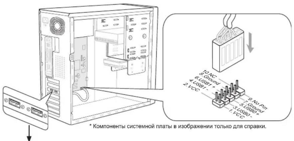
BbHocHa nlaHa USB (oIuHOHaJIbHo)
Bhimahine
BHIMAHNE, BO n36exahanne noBpeXdHn, KOHTaKtby VCC n GND doJxHbI 6bITb npabInbHO noKnIOueHbl.
BbHocHoi pa3bem aydno:JAUD1
3TOT KOHHeKTop NO3BOJnEeT NOkNIOuHTb BbIHOCHO pa3beM aydno Ha nepeDnei NaHEn i COOTBeTcTByeT pyKOBoDcTBy Intel® Front Panel I/O Connectivity Design.
Pa3bem S/PDIF-Out: JSP1
3ToT pa3bEm nCnoB3yeTcA dIy IIOKIIouHnIHTeppeca S/PDIF (Sony & Philips Digital Interconnect Format) dIy nepeDaun 3Byka B uIΦpOBoM φopMaTe.
Pa3bem nocneobateIbHoro npTa: JCOM1
Дань pa3bemЯВЯETcB BlicOKOCKOPOCTHbIM NOcNeIOBaTeNbHbIM NOPTom CBa3N 16550A c 16-байТонпpeDAчeFIFO.KЗTompa3bemyMOxHo HENOCpeIcTBeHHo NOKIIQUHTb NOcNeIOBaTeNbHoe yCTpoIcTBO.
Pazbem TPM Moун: JTPM1
Cnot PCIE (Peripheral Component Interconnect Express)
Cnot PCIE noDpeKnBaet KapTbI paCUnpeHnI HTepeCa PCIE.

PCIE×16 cnot
PCIEx1cnot
Cnot PCI (Peripheral Component Interconnect)
Cnot PCI no3B0JraET yCTaHOBHTb KApTbI LAN, SCSI, USB n dpyrne donoHnTeNbHbIe KapTbI pauchnPENH,NKOTOpbIE COOTBeTCTByIOT cneuФnKaUPINPCI.
32-bitPCI cnot
BhimaHne
Ipeq yctahOBKO uINu 3BneueHnem Kapr pacwnpeHna y6eNTecb, YTO kaBnB nHTAHN OTKIOUeH OT 3NEKTPnuecko CETn. IpOHTte DOKyMeHTaCnHO Ha KapTy paSWPeHn I BvINOJHnTE Heo6XoDnMbIe aannapatHbIe INI npOrpaMHbIe yCTaHOBKn IJa DaHHo IINaTbI, TaKHe KaK NepEmbUcN, NpekNIOUaTeIIu INI KOHpUrpaCnIO BIOS.
Mapspuytn3aun 3anpocob npepbBaHn PCI
IRQ - cokpaueHne ot interrupt request (line) - nHHra 3anpoca npepbBAHnna, annapaTHa JHHN, no KOTopoY yCTpoiCTBa MoryT NOcblNaT cnHaJ npepbBAHmMKponpoeCCopy. ObuHoe noKJIoueHne PCI IRQ K KOHTaKTam uHHbPCI noka3aHo Hnke:
| Прика31 Приka32 Приka33 Приka34 | |
| PCI сnot INT | A# INT B# INT C# INT D# |
Hactpoika BIOS
B 3toI rnaBe npnbOaTc8 oCHObHbIe cBeHeHnO pexnme HacTroKnBIOS (BIOS SETUP), KOTOpBn IIO3BOJAreT yCTaHOBnTB ONTMajbHyIO KOHfNpyaUHO CnCTembl. 3TOr peKIM MoKeT Notpe6oBaTbc B CNeDyUOuX CnyuaX:
Bo Bpem 3aRpy3Kn CnCTeMbI NOBnEeTc Coo6uHne o6 Oun6Ke c Tpe6oBaHHeM 3anyctntb BIOS SETUP.
B cnyuae Heo6xOdMocn 3aMeHnTB 3aBOckne HAcTpoiKn Ha co6cTBeHHbIe.
BhimaHne
-Дя улушеня npo3BODHTeHbOCTn CnCTeMbI, BIOS noctoHHO obHOBJIOTc. IToTOMy, npuBeDEHHoe 3deCb ONcaHne MOKET HeCKONbKO OTJNUaTbCRA OT ONCAHnЯ Дя HOBOB BepCuN, n CnyKNT NCKHouHTeHbHO BAueCTBe npIMepa.
- Пи загузke, в порьо, посе объema памятс STPOKe, ВыBOДNTСОБЗнЧЕНЕ BIOS.ОвьИно Oно ИмeET спедуюши Формат:
E7680IMS.xxx 010611 rje:
1a86yKbacoTBeTcTByeT tinyBIOS (E = EFI)
Cneyuouune 4 uonpbo COOTBeTCTByIOT HOMepy MoJIeJI nnTaJI.
Cnéduyúoùa ébkyBa obo3hauaet npou3BODuTeTn yinnceta (I = Intel, N = nVid ia, A = AMD n V = VIA).
2 nocneHnne 6yKBbl o6o3Haayot npOn3BoNTenr nnatb MS = cTaHdapTHbI 3aKa3uK.
Current CPU / DRAM Frequency
3TN nyHkTbI noka3bIBaOT Tekyu yo yactoty CPU n ckopocb naMRTn. TOnbko dnyteHn.
Adjust CPU Ratio
3TOT NyHKT KOHTPOJINPyET MHOXKITJI, PpeHa3HaueHHb IJa ONpeDeHnRA BHyTpeHHeN TaKTOBOI YactOTbI Npoceccopa B COOTBeTCTBnC BHeUHeN TaKTOBOI YactOTOI NII YactOTOI CnCTeMHOn IINaTBI. OH DoCTyneH ToJIbKO TOrda, KOrDa npOceCCOP NOIDepxNBaET 3Ty FyHKuIO.
Adjusted CPU Frequency
3TOT nyHKT noka3bIbae Teku yu qactoTy CPU. Tolbko dny TeHHa.
Adjust CPU Ratio in OS
BkIIOHTe 3OT nyHKT, OH nO3BOJrEe Bam n3MeHITb yAcToTy CPU B OC cpeIcTBOM npINOxKeHn MSl.
Internal PLL Overvoltage
3TOT nyHKT nCNoB3yeTcIaIpeRnIuPObAHnHaNPaJKeHnPLL.
EIST
TexHONorra Enhanced Intel SpeedStep no3BOJnE yCTaHOBntb yPOBeHb npOn3BOJnTeJIbHOCTn MmKpOnpoUeCCopa. 3TOT nyHKT nOBnETCa NOcIe yCTaHOBKn npOceccopa, KOToPbI noDdepXnBaet TexHONorruo SpeedStep.
>OC Genie Button Operation
3TOT nyHKT no3BOJAreB KKnIOuHTb/BBKIIIOuHTb cyHKUO OC Genie.
DRAM Ratio
NyHKT ynpablenencooTHoWeHem qactOT namrtn.
Adjusted DRAM Frequency
3TOT nyHKT noka3bIbaeTekyu yacToTy DRAM.ToIbKO dnyTeHnA.
DRAM Timing Mode
OnpeJeIeT 6dyT Jn TaMeHr DRAM KOHTpoJInpoBaTbcra DaHHbIMn n3 SPD (Serial Presence Detect) EEPROM Ha moDyNe DRAM. Pn BblOpe 3NaueHnra [Auto] TaMHnRn DRAM, BKIOUaYnyKtB MeHIO, nepeuNCJIeHHbIe HNKe, yCTaHaBJIbNAOTcRBIOS B COOTBeTCTBnC DaHHbIMn n3 SPD. YcTaHObKa 3NaueHnra B [Link] nn [Unlink] No3BOJnEeBpyHyIO peryInpOBAr TaMmHr DRAM DOctynhIe B 3OM MeHIO.
Advanced DRAM Configuration
HaxMnte
Command Rate
3Ta hactpoikka konhtpOnpnyet DRAM command rate.
tCL
3TOT nyHKT KOHTPOINUPyET BpEM 3aepKKn CAS, KOTOpoe onpeDenrEeT nepnoD (B TaKtax rehepaTopa) Mekdy nonyuehnem namrTaIO SDRAM KOMaHDbI UTeHnra Haayanom ee BbINOJIHeHH.
tRCD
Пи obHOBJIeHn DRAM, cTpOKn n CTOn6cbl aApceCyIOrca Pa3dEnbHo. 3ToT nyHKT no3BOJnE rBam onpeJeNt b Bpem na nepexoJa oT RAS (row address strobe) K CAS (column address strobe). Yem MeHbWe TaKToB, Tem 6bIcTpee pa6Ota DRAM.
tRP
3TOT nyHKT KOHTPOINpye T KOINueCTBO TaKTOB, PpeIOCTaBnREMbIX DJIg PpeI3apraRow Address Strobe (RAS). EcnBbIDeJETc HEDOCTaTOUHOE BpEMg DnToro, UTo6bl RAS Ha6paJ Heo6xOIMbI 3apJd, PerEHPauzr DRAM MoKet OKa3aTbcr HENONHOI INPnBEcTI K NOTEpe DaHHbIX. 3TOT NyHK T pImeHM, TOJbKO KOrDa BCNCTeMe yCTaHOBJIeHa CInHXPOHN3IPOBaHHa NamrDrAM.
tRAS
3Ta yctaHOBka onpeDeJraT Bpemr, KOTOpoe RAS 3aTpauNbaet Ha YTeHne n 3aIncB RaYeKy PAmrTu.
tRFC
3Ta yctaHOBka onpeDeJIeT BpEMr, KOtOpoe RFC 3aTpauNbaET Ha YTeHne n 3aIncb B Jaey Ky PAMrTu.
tWR
MnHmAbhag BpeMeHHa 3aepkka dIy BbINOJIHeHg Oepaun 3aIncn nepeKOMaHDoI pEa3apJa. I03BOJraT yCINITeJIaM CHTbIBaHn 3aIncatb daHHbIe Byaekn namrtn.
tWTR
MunHMaJIbHaB BpeMeHHa 3aepKka MExdy BblIOJIHeHnEM KOMaHdbI 3aIIcN HauJIOM KOMaHdbI CHTbIBaHnI CTOn6ca. N03BOJrET CNTeMe BBoJa/BbIBOda c6pocTb Ha npJxehna Ha ycNJITeJX CHTbIBaHnI.
TRRD
OnpeIeIeIeT 3aIepKky nepexOda OT aKTNBHOrO-K-aKTNBHOMy COCTOHHIO dIpa3HbIX 6aHKOB.
tRTP
BpeMeHHbI INHTepBaJI Mekdy KOMaHdAmu YTeHnI nPpe3apraJa.
tFAW
3TOT nyHKT nCnoJb3yETc dIy yCTaHOBKn TaMmHROB tWCL (Write CAS Latency).
tCKE
3TOT nyHKT nCNOJb3yeTcra JIy yCTaHOBKn TaIMMHROB tCKE.
tRTL
3TOT nyHKT nCNoB3yeTcra yCTaHOBKn TaMnHroB tRTL.
Advanced Channel 1/2 Timing Configuration
Haxmte
GT OverClocking
3TOT NyHKT NO3BOJRAET BKHIOUHTb/ BbIKHIOUHTb pa3ROH BUNDeOKapTbl.
GT Ratio
3Ta HacTpoiKa KOHTpOINpye T OTHoUeHne TaKTOB OaCTOTbI BnDeOKapTbI, YTObI OHa pa60TaET B pa3HbIX COyTeAHHx YaCTOT.
Adjusted GT Frequency
3TOT nyHKT noka3bIbae Teku yu chaToTy BndeokapTa. TOnbko dny TeHna.
Spread Spectrum
Tak KAK TAKTOBBI rehepatop cncTeMHOI PJIaTBI NMnyJbChbI, TO erO pa60Ta Bbl3bIbaET 3neKtpomarHnTHbIe nomex - EMI (Electromagnetic Interference).ФункцЯ Spread Spectrum chnkaet 3TN nomex, rehepupy crnaKeHHbIe NMnyJbCbl.
BhimaHne
- Ecnn y Bac Het npoblem c nomexamn, octabte 3naueHne [Disabled] (3anpeucho)Для Лушewи сtabunbHOCTN IN pOON3BOUNTEJIbHOCTN. Ondako, ecnn y Bac BO3HnKaHT 3NeKtpomarHnTHbIe nomexn, BbIbepuTe Spread Spectrum dIra nx yMehbSeHnA.
- Yem 60nbwe 3naueHne Spread Spectrum, Tem Hnke 6ydet ypoBeHb 3NeKtpomarHnTHbIX NOMex, Ho CnCTema CTaHET MeHee CTabnBHO. IInr BblOpa NOxOJaIero 3naueHnra Spread Spectrum, CBepbTecb co 3naueHnmau ypoBHei 3NeKtpomarHnTHbIX NOMex, yCTaHOBnEHbIX 3aKOHOdaTeJIbCTBOM.
He 3a6ydbTe 3anpeTb nCnONb3OBaHne fynKcunn Spread Spectrum, ccn BBi «pa3roHaeTe» cnCTemHyIO nnaty. 3TO Heo6xOJMo, TaK KaK daXe He6oJbWoJ dpe6e3r CnHaNoB TaKToBOrO rHePaTopa MoKeT npUBeCTN K OTKa3y «pa3oRHaHHoro» npoueccopa.
DRAM Voltage
3TOT nyHKT nCnoNb3yETc dIy perynipOBaHnHa npJxKHe naMAYT.
CPU Features
HaxmTe
Hyper-threading
Ipoueccop nCnoB3yET texHONrHo Hyper-Threading dnyyBeJIuYeHn npOn3BOIDTeNbHOCTn. 3Ta texHoJOrn no3BOJAE T ybM HabOpam perNcTPOB B npOeCCope nCNoHNrTb NHCTpyKUn OndHOBpeMHNO. 3To yBeJIuHBAe T npOn3BOIDTeNbHOCTb CnCTeMbI. PnBbIKIOUeHm NToI cyHKUn, npOeCCOP nCNoHNRe T NcHTpyKUn c NOMOUsIO OdHoro Habopa rperNcTPOB. BbIKIOUHTe 3TO nYHKt, ecn OepaunOHHa CnCTema BaWero KOMNBOTepa He NODepXnBAe FyHKUno HT, B npOTNBHom cNyuae 3TO MOKeT pINBecTN K HeCTa6NJbHOCTn.
BhimaHme
Дя paBOTocno6HocTN texHONorN Hyper-Threading, Tpebyetc HAnuYe BceX HIXeCNeDyUOxKOMNoHErTOB:
CPU: Ppouecccop Intel c texhONorneHT;
- Yuncet: Yuncet Intel®, noДeprxuBaIoUm TeXHoIoruH HT;
BIOS:BIOS, noDpeKbBaOuN TeXHONrIO HT, n BKnIOUeE;
OS:OnepaunOHnA cnCTema, noDpeKnBaIOuaT texHONrIO HT.
3a dononHntbHn Hnpmaueo Hyper-threading, obpaauTecb Ha Be6caT: www.intel.com/info/hyperthreading
Active Processor Cores
3TOT nyHKT no3BOJareT BbI6paTb KOJIynchecTBo aKTHBbIX Jaep npOceccopa.
Limit CPUID Maximum
3TOT nyHKT npedHa3HaueH dIra orpaHnueHnaI nnHHbI ndHTnФkaunOHoro Homepa npoueccopa nepedaBaemoro B onepaunOHHyO cnCTemy.
Execute Disable Bit
IcnoIb3OBAHne TexHONOrn Execute Disable Bit Intel no3BOnJeT n36eRaTb y3BMocTeB b13bBaEMbIX BpeHOHcHbIMn npOrpaMMaMn 3KcNJIyATnpUOUMn Oun6Kn TnPa "buffer overflow", ecnn 3Ta TexHONORn NOdepJXNBaeTcR ONepaOHNo CnCTeMoN. OHa no3BOJareT npouecCPpy pa3DeJIaTb 3OHbI B naMaTn B COOTBeTCTBn C TeM, XpaHNTcR JIN B naMaTn NCNOJIHReMbI KOd NII HET. KOrDa BpeHOHChA npOrpAMMa nonbItaeTcR BCTaBnTb KOD B 6ByFep, npoueCCop 3anPeTIT NcNoJHeHne KoJa, YTO OCTaHOBnT pacnpocTaHeHne BpeHOHcHOb INpOrpaMMbl.
Intel Virtualization Tech
3TOT NyHKT NcNoJIb3YeTCdIe BkHIOUeHn/ByIKHIOUeHn TexHOJOrn Intel Virtualization. 3a DononHntelbHOINHΦOpMaunE CMOTpTe OΦΦuHaNbHbI Be6caIT Intel.
Power Technology
3TOT nyHKT no3BONrEe Bb6paTb peKIM texHoiIorN Intel Dynamic Power.
C1ESupport
Bknouhte 3TOT nyHKT dIa cHnKeHH aHepronoTepeBneHHa CPU, kOrda OH He pa6oTaET. He Bce npocecopbl noDepKbAot Enhanced Halt state (C1E).
OverSpeed Protection
Функцог Overspeed Protection oTo6paxaet notok BbIuNCHeHn CPU n ero əHepronotpe6JIeHne. EcIn OHO npeBbICNT onpeDeIeHHybl ypoBeHb, To npouceccop aBTOMaTnueCKn NOHN3NT TaKTOByU qAcToTy. EcIn Bbl co6npaIteCb pa3roHrTb CPU, To yCTaHOBnTE 3TOT napaMeTp B [Disabled].
Intel C-State
C-state - 3TO TexHONORn ynpablenn nHTaHnem, npKTHBaun KOTOpO 3NaHTeNbHO naaet 3Hepro notpe6JIeHne npoceccopa B cnae um pexime. 3TOT nyHKT DOCTyPeH TOIbKO npn IcNoJIb3OBAHm CPU c noDepkko TExHONOrn Cstate.
Package C-State limit
3TOT nyHKT no3BONaTe Bb6paTb C-state limit.
Long duration power limit(W)
3TOT nyHKT NO3BOJARET peryIINPOBaTb JIMNT MOUHOCTN TDP B TeueHN INpOdoJXHTeBHORO BpeMeHN.
Long duration maintained(ms)
3TOT nyHKT no3BONrEYcTaHOBnTB Bpemra 60ToB I neperpyKeHHOM pexKIMe.
Short duration power limit(W)
3TOT nyHKT no3BOJareT peryJInpoBaTb JIMMUT MOUHocTn TDP B TeueHn KOpOTKOrO npomexkyTka BpeMeHn.
Primary/ Secondary plane turbo power limit (W)
3TOT nyHKT no3BONJET peryIINPOBaTb JIMNT MoUHOCTN TDP nIepBnUHoro/ BTOPNUHoro plane turbo.
CbeHnO nporpaMMHom oBecepeHH
YctahOBnTe B npBOD nck Driver/Utility (DpaBepb i yTuNTbI) n3 KOMnKeTaNocTabKn CnCTeMHOn INaTbI. ABToMaTnueckN 3aNyCTntc NHCTaJIaZnHaXKMnTe HaHa3BaHne dpaBepa/ yTuNTbI n CneDuYNe IHCTpyKUmHa 3kpaHe dJy 3aBepSeHnIHCTaJIaZn. Dnck Driver/Utility coedePknt:
- Driver menu (MeHIO npaBepOB): PpeCTabJnE TnepeHb DocTyNHbIX dpaBepOB. YctaHOBNTe dpaBepbl IINI NOKJIPOeHnHEo6XODIMbIX YCTPOJCTB.
- Utility menu (MeHIO yTNIIT): P03BOJRAET yCTaHOBNTb DOcTyNHbIe yTNIITbl.
Service base menu (MeHIO cepBnCHo6a3bI):P03BOJIAET COEINHTb OΦnuaHBnBe6caT MSI. - Product info menu (MeHIO npOyKToB): Poka3bIbaeT nocJeHIO HOpMaCuHO npOyKtax MSl.
- Security menu (MeHIO 6e3oNaChocTu): PpeiCTabnre TnoJe3HbIe aHTNBpyChbIe npOrpaMMbl.
BhVMaHmE
Noxanynta, noceTne Be6caT MSI dnyeHn CaMbIX HObIX dpaBepOB IN BIOS, KOTOpblie No3BOJr T yNcHtB npOn3BOJnteHbHOCTb CNCTEmbl.