
MMT330 - Temperature and humidity sensor VAISALA - Free user manual and instructions
Find the device manual for free MMT330 VAISALA in PDF.
| Product type | Humidity and temperature transmitter for oil |
| Brand | VAISALA |
| Model | MMT330 |
| Category | Temperature and humidity measurement probe |
| Power supply | 24 VAC (optional power supply module for 100-240 VAC) |
| Display | With screen (optional) |
| Analog outputs | 4-20 mA (configurable via DIP switches) |
| Serial communication | RS-232 (service port), RS-485 (optional module) |
| Sensor | Vaisala HUMICAP® for humidity in oil |
| Humidity measurement range | 0 ... 1 aw (water activity) |
| Operating temperature range | -40 °C ... +80 °C |
| Dimensions (enclosure) | Approximately 200 x 150 x 100 mm (standard) |
| Weight | Approximately 1 kg |
| Mounting | Wall mounting (4 M6 screws not supplied) |
| Enclosure material | Robust plastic |
| Protection rating | IP65 (estimated) |
| Available languages | French, English, German, Spanish, Finnish, Japanese, Dutch, Swedish, Chinese |
| Calibration | Factory calibrated; recalibration possible by user or at service center |
| Maintenance and cleaning | Clean the exterior with a soft, dry cloth; avoid solvents |
| Safety | Electrical connection by a certified electrician for the mains module; do not connect the same wire to + and - of two transmitters |
| Spare parts and repairability | Optional modules (relay, RS-485, power supply); repair by Vaisala Service Centers |
| General information | Quick start guide included; full user manual available online |
Frequently Asked Questions - MMT330 VAISALA
User questions about MMT330 VAISALA
0 question about this device. Answer the ones you know or ask your own.
Ask a new question about this device
Download the instructions for your Temperature and humidity sensor in PDF format for free! Find your manual MMT330 - VAISALA and take your electronic device back in hand. On this page are published all the documents necessary for the use of your device. MMT330 by VAISALA.
USER MANUAL MMT330 VAISALA
This Quick Guide provides an overview on how to install Vaisala HUMICAP® Humidity and Temperature Transmitter Series HMT330, Vaisala DRYCAP® Dewpoint and Temperature Transmitter Series DMT340 and Vaisala HUMICAP® Moisture and Temperature Transmitter Series for Oil MMT330. Please refer to the relevant User's Guides for detailed information on the use of the products.
Things to Consider
When Measuring Dewpoint
-
If a sampling system is built instead of direct probe installation, it is important that the system is leak-proof. Recommended material for sampling system construction is stainless steel. Also PTFE may be used down to dewpoints of -40^ / -40^ .
-
Dewpoint is a pressure dependent parameter. It is important that the pressure at the sensor is the true process pressure. The temperature is not of major importance, as long as it is above the process dewpoint in order to avoid condensation.
When Measuring Relative Humidity
In humidity measurement it is essential that the temperature of the probe and the measured gas is the same. Even a small
difference in temperature between the environment and the probe can cause an error of several percentages in RH.
Mounting the Probes with Cable
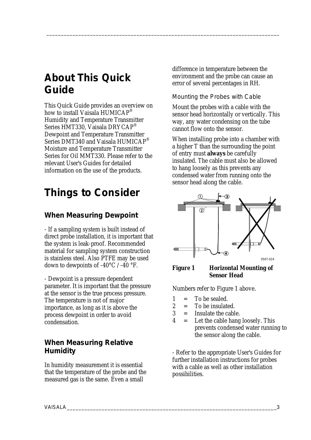
Mount the probes with a cable with the sensor head horizontally or vertically. This way, any water condensing on the tube cannot flow onto the sensor.
When installing probe into a chamber with a higher T than the surrounding the point of entry must always be carefully insulated. The cable must also be allowed to hang loosely as this prevents any condensed water from running onto the sensor head along the cable.
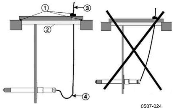
Figure 1 Horizontal Mounting of Sensor Head
Numbers refer to Figure 1 above.
1 = To be sealed.
2 = To be insulated.
3 = Insulate the cable.
4 = Let the cable hang loosely. This prevents condensed water running to the sensor along the cable.
- Refer to the appropriate User's Guides for further installation instructions for probes with a cable as well as other installation possibilities.
When Measuring Moisture in Oil
-
The measurement should be done in a location that provides a representative sample of your entire oil system (for example, a high flow feed line or return line to reservoir). The sensor reads that which it is in contact with only.
-
Locations to avoid include the bottom of oil reservoirs and bends in a pipeline where free water may settle out as well as areas where heavy air bubbling could occur due to turbulence caused by pumps or agitators.
Transmitter Housing Standard Installation
Mount the housing by fastening the transmitter to the wall with 4 screws, for example M6 (not provided). Refer to the User's Guides for the use of the optional mounting plates.
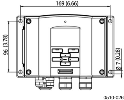
Figure 2 Standard Mounting Dimensions (in mm/inch)
Operation
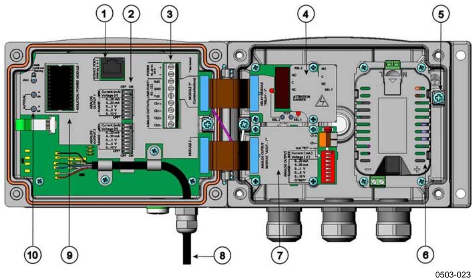
Figure 3 Inside of the Open Transmitter
Numbers refer to Figure 3 above.
1 = Service port (RS-232)
2 = Dip switches for analog output settings
3 = Power supply and signal wiring screw terminals
4 = Relay/RS-485 module (optional)
5 = Grounding connector
6 = Power supply module (optional)
7 = Relay module/third analog output module (optional)
8 = Probe
9 = Output isolation module/DC-DC converter (optional)
10 = Adjustment buttons with indicator led
Wiring
- A single electrical cable with a screen and three to ten wires is recommended for power and analog/serial connections. The cable diameter should be 8 11 ~mm . The number of cable bushings depends on the transmitter options. Ground the screen of the electrical cable properly to achieve the best possible EMC performance.
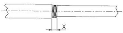
Fig. 1
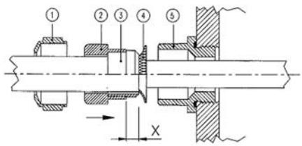
Fig. 2
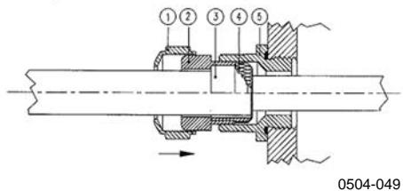
Fig. 3
Figure 4 Grounding the Screen of Electrical Cable
a. Cut back outer sheath to desired length.
b. Cut back screen braiding or screen foil to dimension X (see figure 2).
c. Push the domed cap nut (item 1) and the seal insert with contact socket of the gland (item 2 + 3 ) onto the cable as shown in the diagram.
d. Bend over the screen braiding or screen foil by about 90^ (item 4).
e. Push the seal insert with the contact socket of the gland (item 2+3) up to the screen braiding or screen foil.
f. Mount lower part (item 5) on the housing.
g. Push the seal with the contact socket of the gland and (item 2+3) flush into the lower part (item 5).
h. Screw the domed cap nut (item 1) onto the lower part (item 5).
When connecting to a 24 VAC power supply a separate floating supply for each transmitter is recommended.
WARNING
The AC (mains) power connection may be connected to the power supply module only by an authorized electrician.
WARNING
Make sure that you connect only unpowered wires.
CAUTION
In case you have only one AC supply, never connect same wire to the + connector of a transmitter and to the - connector of another one. This will short-circuit the transformer.
Starting Operation
- Within a few seconds after power-up the led on the cover of the transmitter is lit continuously indicating normal operation. When the transmitter equipped with a display is turned on the first time, the language selection window opens.
- Select the language with arrow buttons and press the SELECT button.

Figure 5 Language Selection Menu
- The pressure has an effect on humidity calculations and accuracy. Therefore, accurate calculations can be achieved only when the process pressure is taken into account.
- In DMT340, the start-up time is about 6 minutes due to a self-diagnostics procedure. During this, the outputs are frozen.
Maintenance
-
The transmitter is fully calibrated and adjusted as shipped from factory.
-
Calibration must be done always when there is a reason to believe that the device is not within the accuracy specifications. Calibration and adjustment can be carried out in Vaisala Service Centers or by the user
NORTH AMERICAN SERVICE CENTER,
phone: +1 781 933 4500
EUROPEAN SERVICE CENTER,
phone: +358 9 8949 2658
TOKYO SERVICE CENTER,
phone: +81 3 3266 9617
BEIJING SERVICE CENTER ,
phone: +86 108526 1199
www.vaisala.com
Brand : VAISALA
Model : MMT330
Category : Temperature and humidity sensor