
D2 - Audio Amplifier BEGLEC - Free user manual and instructions
Find the device manual for free D2 BEGLEC in PDF.
| Product Type | Professional 2-channel audio amplifier |
| Available Models | D2-900, D2-1200, D2-1500 |
| Stereo Power (8Ω, THD<0.1%) | D2-900: 2x300 W RMS; D2-1200: 2x400 W RMS; D2-1500: 2x500 W RMS |
| Stereo Power (4Ω, THD<0.1%) | D2-900: 2x450 W RMS; D2-1200: 2x600 W RMS; D2-1500: 2x750 W RMS |
| Bridged Power (8Ω, THD<0.1%) | D2-900: 900 W RMS; D2-1200: 1200 W RMS; D2-1500: 1500 W RMS |
| Frequency Response | 20 Hz - 20 kHz (±0.5 dB) |
| Total Harmonic Distortion | < 0.1% |
| Signal-to-Noise Ratio | > 90 dB |
| Damping Factor | > 600 |
| Built-in Active Filters | Crossovers 24 dB/octave, adjustable from 90 to 250 Hz (HPF, LPF, OFF) |
| Operating Modes | Stereo, Mono, Bridge |
| Inputs | 2 balanced XLR (channels 1 and 2) |
| Speaker Outputs | 3 Speakon (L, R, Bridge) |
| Link Outputs (Daisy chain) | 2 male XLR (LINK) |
| Power Supply | 230 V AC / 50 Hz, with soft start |
| Dimensions (W x D x H) | 482 x 473 x 88 mm (2U) |
| Weight | D2-900: 17 kg; D2-1200: 19 kg; D2-1500: 20.5 kg |
| Cooling System | Dual-speed fan |
| Built-in Protections | Soft start, current limiter, DC protection, overheating, overload, and short circuit |
| Maintenance Instructions | Clean with a slightly damp soft cloth. Regularly vacuum the ventilation openings. |
| Installation | 19" rack mount (4 screws), allow 5 cm clearance around for ventilation. |
| Operating Temperature | Max. 45°C |
| Warranty and Repairability | No user-serviceable parts. Have maintenance performed by a qualified technician. Use fuses of the same type. |
Frequently Asked Questions - D2 BEGLEC
User questions about D2 BEGLEC
0 question about this device. Answer the ones you know or ask your own.
Ask a new question about this device
Download the instructions for your Audio Amplifier in PDF format for free! Find your manual D2 - BEGLEC and take your electronic device back in hand. On this page are published all the documents necessary for the use of your device. D2 by BEGLEC.
USER MANUAL D2 BEGLEC
Copyright © 2007 by BEGLEC cva.
Reproduction or publication of the content in any manner, without express permission of the publisher, is prohibited.

Version: 1.1
JBSYSTEMS
THE POWER SOURCE FOR DJ'S


EN - DISPOSAL OF THE DEVICE
Dispose of the unit and used batteries in an environment friendly manner according to your country regulations.
FR-DECLASSES L'APPAREIL
Thank you for buying this JB Systems® product. To take full advantage of all possibilities, please read these operating instructions very carefully.
FEATURES
This unit is radio-interference suppressed. This appliance meets the requirements of the current European and national guidelines. Conformity has been established and the relevant statements and documents have been deposited by the manufacturer.
- Professional 2-channel amplifier with built-in active crossover.
- Very compact housing, only 2U (88mm) high
- Oversized power supply guarantees a powerful bass reproduction
- Built-in active crossovers: no need for separate crossover units to setup an active system.
Each channel equipped with a 24dB/ocbase crossover: adjustable crossover point (90~250Hz) and 3 operation modes: HPF (high pass filter) + LPF (low pass filter) + OFF (no filter) - Two amplifier modes: stereo and bridge
- Peak limiters can be switched on/off
- Soft start power supply
- Very efficient cooling
- DC fault protection
High temperature protection
Overload and short circuit protections
Balanced XLR inputs - XLR-outputs: daisy chaining of several amplifiers
- 3 Speakon® outputs: left + right channels + bridge
- 3 models with different output power available.
BEFORE USE
- Before you start using this unit, please check if there's no transportation damage. Should there be any, do not use the device and consult your dealer first.
- Important: This device left our factory in perfect condition and well packaged. It is absolutely necessary for the user to strictly follow the safety instructions and warnings in this user manual. Any damage caused by mishandling is not subject to warranty. The dealer will not accept responsibility for any resulting defects or problems caused by disregarding this user manual.
- Keep this booklet in a safe place for future consultation. If you sell the fixture, be sure to add this user manual.
- To protect the environment, please try to recycle the packing material as much as possible.
Check the contents:
Check that the carton contains the following items:
- User manual
D2-amplifier
SAFETY INSTRUCTIONS:
CAUTION
RISK OF ELECTRIC SHOCK DO NOT OPEN

CAUTION: To reduce the risk of electric shock, do not remove the top cover. No user-serviceable parts inside. Refer servicing to qualified service personnel only.

The exclamation point within the equilateral triangle is intended to alert the user to the presence of important operation and maintenance (servicing) instructions in the literature accompanying this appliance.

This symbol means: indoor use only
This symbol means: Read instructions
- To prevent fire or shock hazard, do not expose this appliance to rain or moisture.
- To avoid condensation to be formed inside, allow the unit to adapt to the surrounding temperatures when bringing it into a warm room after transport. Condense sometimes prevents the unit from working at full performance or may even cause damages.
- This unit is for indoor use only.
- Don't place metal objects or spill liquid inside the unit. No objects filled with liquids, such as vases, shall be placed on this appliance. Electric shock or malfunction may result. If a foreign object enters the unit, immediately disconnect the mains power.
- No naked flame sources, such as lighted candles, should be placed on the appliance.
- Don't cover any ventilation openings as this may result in overheating.
- Prevent use in dusty environments and clean the unit regularly.
- Keep the unit away from children.
- Inexperienced persons should not operate this device.
Maximum save ambient temperature is 40^ . Don't use this unit at higher ambient temperatures. - Minimum distances around the apparatus for sufficient ventilation is 5cm .
- Always unplug the unit when it is not used for a longer time or before you start servicing.
- The electrical installation should be carried out by qualified personal only, according to the regulations for electrical and mechanical safety in your country.
- Check that the available voltage is not higher than the one stated on the rear panel of the unit.
- The socket inlet shall remain operable for disconnection from the mains.
- The power cord should always be in perfect condition. Switch the unit immediately off when the power cord is squashed or damaged. It must be replaced by the manufacturer, its service agent or similarly qualified persons in order to avoid a hazard.
- Never let the power-cord come into contact with other cables!
- When the power switch is in OFF position, this unit is not completely disconnected from the mains!
- This appliance must be earthed to in order comply with safety regulations.
- In order to prevent electric shock, do not open the cover. Apart from the mains fuse there are no user serviceable parts inside.
- Never repair a fuse or bypass the fuse holder. Always replace a damaged fuse with a fuse of the same type and electrical specifications!
- In the event of serious operating problems, stop using the appliance and contact your dealer immediately.
- Please use the original packing when the device is to be transported.
- Due to safety reasons it is prohibited to make unauthorized modifications to the unit.
INSTALLATION GUIDELINES:
- Install the unit in a well-ventilated location where it will not be exposed to high temperatures or humidity.
- Placing and using the unit for long periods near heat-generating sources such as amplifiers, spotlights, etc. will affect its performance and may even damage the unit.
- The unit can be mounted in 19-inch racks. Attach the unit using the 4 screw holes on the front panel. Be sure to use screws of the appropriate size. (screws not provided)
-
Take care to minimize shocks and vibrations during transport.
-
When installed in a booth or flight case, please make sure to have good ventilation to improve heat evacuation of the unit.
- To avoid condensation to be formed inside, allow the unit to adapt to the surrounding temperatures when bringing it into a warm room after transport. Condense sometimes prevents the unit from working at full performance.
CLEANING THE UNIT:
Clean by wiping with a cloth slightly dipped with water. Avoid getting water inside the unit.
Do not use volatile liquids such as benzene or thinner which will damage the unit.
Clean the ventilation holes regularly with a vacuum cleaner. This increases the cooling capacity of the amplifier fans and helps preventing temperature overheat.
CONNECTIONS
Be sure to turn off the unit before you make changes to the wiring. For the signal inputs we recommend using the XLR-connections. Use good quality signal cables to ensure excellent audio quality. For the speakers you must use the Speakon® outputs. In the description of the unit you will find more information on how to connect the amplifier.
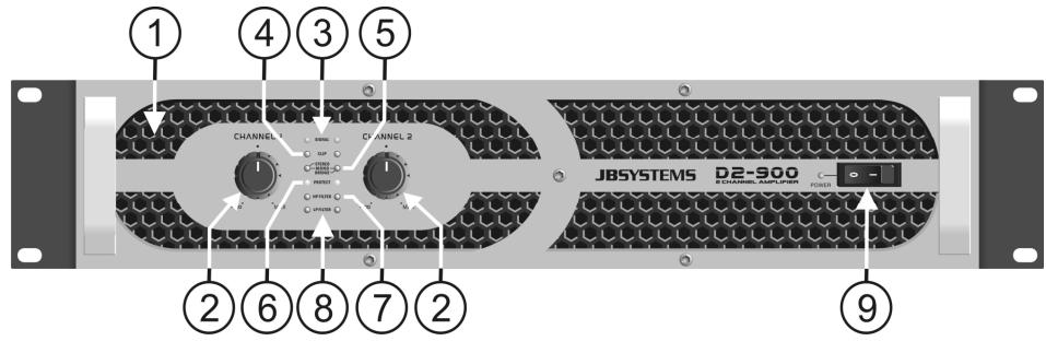
FUNCTIONS
- VENTILLATION HOLES: during its operation the amplifier produces heat that needs to be dissipated. The fans inside the amplifier must be able to evacuate the heat in the most effective way. Therefore is it very important not to cover any of the ventilation openings as this may result in overheating. Clean the ventilation holes regularly with a vacuum cleaner. This increases the cooling capacity of the amplifier fans and helps preventing temperature overheat.
- GAIN CONTROLS: These potentiometers are used to control the input sensitivity of the amplifier. Each channel has its own control.
You can use these controls to set the maximum sound level of your setup:
- Turn both controls on the amplifier to the left.
- Put on some music on and make sure the VU meters on your mixer are at 0dB. (from time to time the red zone is lit)
- Set the Master output from your mixer to maximum.
- Open the Gain controls from the amplifier until the maximum desired sound level is reached.
- Make sure nobody can reach the Gain controls of the amplifier.
You have just set the maximum level the DJ is able to produce. Your neighbors will be glad... (in some cases the DJ is not )
Note: In Bridge mode, only the gain control of the left channel is used to adjust the input sensitivity.
- SIGNAL LEDs: these LEDs indicate that a music signal is present at the inputs.
- CLIP LEDs: Turn on just before the maximum, distortion free, output level of the amplifier. They indicate that the internal limiter starts working. The clip LEDs may turn on shortly from time to time but they may certainly not turn on for longer periods. In this case you have to turn the output level down!
- OPERATION MODE LEDs: These LEDs indicate the operation mode. Switch (13) on the rear panel is used to choose one of the 3 possible modes:
-
STEREO MODE: This is the most common mode, both channels are working separately.
-
MONO MODE: Both LEDs (5) are lit. Basically this is identical to stereo mode but the inputs of both channels are linked so the output will be mono. In this case you only need to use the input of the left channel to drive both output channels.
-
BRIDGE MODE: Both channels are linked in "bridge mode" to obtain a mono output with much higher power.
-
PROTECT LEDs: The protection LED is on when the speakers are disconnected from the amplifier. This occurs in the following situations:
-
During the first seconds after switching on the amplifier.
- When the temperature of the power stage becomes too high.
- In case of a technical defect: DC protection!
-
While switching the amplifier off, the "protect led" turns on for a short time.
-
HP FILTER LED: Indicates that the high pass filter (HPF) is switched on for this channel (left and right channels have their own HPF LED) Please refer to numbers 18 and 20 to learn more about this filter.
- LP FILTER LED: Indicates that the low pass filter (LPF) is switched on for this channel (left and right channels have their own LPF LED) Please refer to numbers 18 and 20 to learn more about this filter.
- MAINS SWITCH: Used to turn the amplifier on and off. A few seconds after switching on the amplifier it is ready for operation. The blue led is on when you turn the amplifier on.
-
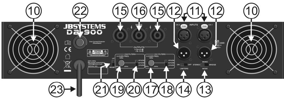
FAN & VENTILLATION HOLES: during its operation the amplifier produces heat that must be dissipated. The fans inside the amplifier must be able to evacuate the heat in the most effective way. Therefore is it very important not to cover any of the ventilation openings as this may result in overheating.
-
XLR inputs: You can connect these balanced inputs to balanced and unbalanced line level audio sources:
-
Balanced source: Use good quality XLR/XLR balanced audio cables.
Wiring of the XLR connector:
PIN1: GND PIN2: pos+ PIN3: neg- -
Unbalanced source: Use good quality XLR/cinch audio cables.
Wiring of the XLR connector:
PIN1: GND PIN2: pos+ PIN3: GND (connect to PIN1) -
XLR LINK outputs: in several cases you need a lot of power that can't be produced by only 1 amplifier. In these cases the link outputs are used to daisy chain the inputs/outputs of several amplifiers. The wiring if these male XLR outputs are identical to the inputs.
-
OPERATION MODE switch: Used to set the operation mode of the amplifier. The most common operation mode is "stereo". If you need more power, you can operate the amplifier in bridge mode. Refer also to point 5 for more information.
-
LIMITER switch: This amplifier has built-in limiters to protect both the amplifier and the connected speakers. We strongly suggest to put this switch in on position at all times. Nevertheless if you are experienced or you use an external limiter you can switch the internal limiters off.
-
L+R SPEAKON OUTPUTS: use these Speakon connectors to connect your speaker cabinets in stereo or mono mode. Wiring of these connectors is as follows:
-
POS(+) = Speakon® connector PIN1+ and PIN2+
- NEG(-) = Speakon® connector PIN1- and PIN2-
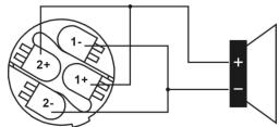
SPEAKON WIRE CONNECTION
-
BRIDGE SPEAKON OUTPUT: use this Speakon connector to connect your speaker cabinet in bridge mode. Refer to points 5 and 12 for more information. Wiring of this connector is as follows:
-
POS (+) = Speakon connector PIN1 + and PIN2 +
-
NEG(-) = Speakon connector PIN1- and PIN2-
-
CH1 FILTER CONTROL: used to adjust the crossover frequency of the internal crossover for channel1. You can adjust the frequency between 90Hz and 250Hz: perfect to make an active system based on a subwoofer + top cabinet! For most subwoofer applications a crossover point between 90Hz and 150Hz is OK, however while listening and comparing you will easily find the optimal settings for your system.
-
CH1 FILTER SWITCH: used to set the desired filter for channel1: high pass, low pass or no filter:
-
High pass filter (HPF): use this filter when you want to connect a small top cabinet to the output of channel1. See the chapter "How to use" for more information.
- Low pass filter (LPF): use this filter when you want to connect a subwoofer cabinet to the output of channel1. See the chapter "How to use" for more information.
-
No filter: use this option if you want to connect a normal full range speaker cabinet to channel1, this is the most common user mode.
-
CH2 FILTER CONTROL: Exactly the same function as described in number 17 but now for channel 2.
- CH2 FILTER SWITCH: Exactly the same function as described in number 18 but now for channel 2.
- GROUND LIFT switch: In some cases nasty hum noises can occur due to ground loops in your setup. Setting the Ground lift switch to the position "lift" breaks the ground loop between the amplifier and the chassis grounds of various other components in your setup. As a result the hum noises disappear.
- RESET button: this amplifier uses an automatic fuse. When the fuse is blown, simply press the button to rearm it.
- MAINS input: When all audio cables are connected, you can connect this cable to mains outlet.
HOW TO USE
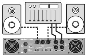
Normal use in stereo mode
Will be used in most cases for a simple setup with 2 speaker cabinets.
- Connect the audio signal to both inputs (11)
- Connect the speaker cabinets to both outputs (15)
- Put both filter switches (18) and (20) to "no filter"
- Put the mode switch (13) to stereo
- Close the gain controls (2)
- Switch the amplifier on (9)
- Open the gain controls (2) to the desired level.
Used with the crossover filters to obtain an active stereo system
Please note that when used in an active setup you need 2 amplifiers to obtain a stereo system. There are 2 different options to connect the amplifiers:
Option1 - one amplifier per side for high and low outputs
In this setup we use channel1 for the top cabinet and channel2 for the subwoofer on both amplifiers. We use one amplifier for the left channel and one amplifier for the right channel.
- Connect the audio signal only to the channel1 input (11)
- Put the mode switch (13) to mono
- Connect the top cabinet to the output (15) of channel1
- Connect the subwoofer to the output (15) of channel2
- Put the filter switch of channel1 (18) to "high pass filter"
- Adjust the crossover frequency of channel1(17)
- Put the filter switch of channel2 (20) to "low pass filter"
- Adjust the crossover frequency of channel2 (19)
- Close the gain controls (2)
- Switch the amplifier on (9)
- Open the gain controls (2) to the desired levels so you have a nice balance between the top cabinet and the subwoofer.
- Further adjust the crossover points of the filters (normally the crossover points of both channels should be equal)
Remark: if your top cabinets can support low frequencies (example: top cabinets based on 15" or 2x15" woofers), you can set channel1 to "no filter". The top cabinets are not filtered which results in more punch for the low frequencies.
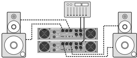
Option2 – one amplifier for top cabinets and one amplifier for subwoofoers
In this setup we use both channels of amplifier A for the top cabinets and both channels of amplifier B for the subwoofer(s). Both amplifiers receive a normal stereo audio signal.
- Connect the stereo audio signal to the inputs of both amplifiers (use a short XLR-cable to daisy chain the inputs of both amplifiers)
- Put the mode switch of both amplifiers (13) to stereo
- Connect the top cabinets to the outputs (15) of amplifier A
- Connect the subwoofer(s) to the outputs (15) of amplifier B
- Put both filter switches on amplifier A to "high pass filter"
- Adjust the crossover frequency (17) for both channels of amplifier A
- Put both filter switches on amplifier B to "low pass filter"
- Adjust the crossover frequency (17) for both channels of amplifier B
- Close the gain controls (2) on both amplifiers
- Switch both amplifiers on (9)
- Open the gain controls (2) of amplifier A to the desired level
- Open the gain controls (2) of amplifier B until have a nice balance between the top cabinets and the subwoofer(s).
Further adjust the crossover points on both amplifiers
Remark: if you only use one powerful subwoofer, you can switch amplifier B to bridge mode and use the bridge output to connect the subwoofer. In this case only the controls of channel1 should be used.
Used in bridge mode, without filters
In this case the amplifier has only one mono output but with a much higher output power.
- Connect the audio signal to the input of channel1 (11)
- Connect the speaker cabinet to the bridge output (16)
- Put both filter switches (18) and (20) to "no filter"
- Put the mode switch (13) to bridge
- Close the gain controls (2)
- Switch the amplifier on (9)
- Open the gain control of channel1 (2) to the desired level. (the gain control of channel2 is not used)
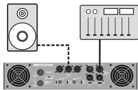
Used in bridge mode, with filters
Below we explain how to connect a powerful subwoofer.
- Connect the audio signal to the input of channel1 (11)
- Connect the subwoofer to the bridge output (16)
- Put the filter switch of channel1 (18) to "low pass filter"
- Adjust the crossover frequency of channel1 (17)
- Put the mode switch (13) to bridge
- Close the gain controls (2)
- Switch the amplifier on (9)
- Open the gain control of channel1 (2) to the desired level. (the gain control of channel2 is not used)
SPECIFICATIONS
| D2-900 | D2-1200 | D2-1500 | |
| Power stereo 8Ω (1kHz, THD+N<0,1%) | 2x 300Wrms | 2x 400Wrms | 2x 500Wrms |
| Power stereo 4Ω (1kHz, THD+N<0,1%) | 2x 450Wrms | 2x 600Wrms | 2x 750Wrms |
| Power bridge 8Ω (1kHz, THD+N<0,1%) | 900Wrms | 1200Wrms | 1500Wrms |
| Freq. Resp. (+/-0.5dB) | 20-20.000Hz | ||
| Activecrossover | Built-in 24dB/oct. crossover 90~250Hz | ||
| Input sensitivity | 770mV | ||
| Input impedance | 20kΩ Balanced, 10kΩ un-Balanced | ||
| S/R ratio | >90dB | ||
| Damping factor 8Ω/1kHz | >600 | ||
| Cooling | Dual speed fan cooling | ||
| Input Connections | Balanced XLR | ||
| Output Connections | 3 Speakon® for Stereo & Bridge Output | ||
| Power Supply | 230Vac / 50Hz | ||
| Dimensions (mm) | 482 x 473 x 88 | ||
| Weigth (kg) | 17 | 19 | 20,5 |
| THD | < 0.1% | ||
| Crosstalk @ Rated Output 8Ω/1kHz | < 75dB | ||
| Protection | Soft Start, Short Circuit, Limiter, DC Fault, AC Line Fuse Thermal Cut | ||
Every information is subject to change without prior notice. You can download the latest version of this user manual on our website: www.beglec.com
MODE D'EMPLOI
PIN1: GND PIN2: pos+ PIN3
PIN1: GND PIN2: pos+ PIN3: neg-
PIN1: GND PIN2: pos+ PIN3: neg-
Ligaoes do conector XLR:
PIN1: GND (Terra) PIN2: pos+ PIN3: GND (conectado ao PIN1)