
MF-8100 - INSTALLATION - Portable Refrigerator DOMETIC - Free user manual and instructions
Find the device manual for free MF-8100 - INSTALLATION DOMETIC in PDF.

| Product Type | Marine macerating toilet with electric flush |
| Brand | DOMETIC |
| Model | MF-8100 (MasterFlush 8100 Series) |
| Standard height (seat) | 432 mm / 17 in |
| Low height (seat) | 349 mm / 13.75 in |
| Width (overall) | 375 mm / 14.75 in |
| Standard depth (lid closed) | 813 mm / 32 in |
| Low depth (lid closed) | 711 mm / 28 in |
| Power supply | 12 V DC or 24 V DC |
| Recommended circuit breaker | 20 A (12 V) / 15 A (24 V) |
| Minimum water flow required | 9.5 L/min at 2.5 GPM |
| Discharge inner diameter | 38 mm (1.5 in) or 25 mm (1 in) minimum |
| Maximum horizontal discharge run | 30 m / 98 ft |
| Maximum vertical discharge run | 3 m / 9.8 ft |
| Bowl material | Vitreous ceramic |
| Pump housing material | Glass-filled polypropylene |
| Main functions | Electric flush, macerator pump, hydraulic valve, integrated check valve |
| Compatible water system | Pressurized fresh water or seawater with separate pump |
| Safety | Flood risk: mandatory shut-off valves, vent loops to prevent backflow |
| Installation | Floor or wall mount, with mounting templates provided |
| After-sales service | Contact Dometic: 1-800-321-9886 (US/CA) or international 330-496-3211 |
Frequently Asked Questions - MF-8100 - INSTALLATION DOMETIC
User questions about MF-8100 - INSTALLATION DOMETIC
0 question about this device. Answer the ones you know or ask your own.
Ask a new question about this device
Download the instructions for your Portable Refrigerator in PDF format for free! Find your manual MF-8100 - INSTALLATION - DOMETIC and take your electronic device back in hand. On this page are published all the documents necessary for the use of your device. MF-8100 - INSTALLATION by DOMETIC.
USER MANUAL MF-8100 - INSTALLATION DOMETIC
1 Notes on using the manual 3
2 General safety instructions 3-4
3 Components 5
4 Specifications 6
5 Installation 7-12
6 Customer service. 13
1 Notes on using the manual

Caution!
Safety Instruction: Failure to observe this instruction can cause material damage and impair the function of the device.

Note
Supplementary information for operating the device.
fig. 1 A, page 2 : This refers to an element in an illustration. In this example, item A in figure 1 on page 2.
2 General safety instructions
The manufacturer will not be held liable for claims for damage resulting from the following:
- Faulty assembly or connection
- Damage to the unit from mechanical influences, misuse or abuse
- Alterations to the unit without express written permission from the manufacturer
- Use for purposes other than those described in the operating manual
2.1Warnings - marine applications
The following statements must be read and understood before installing, servicing and/or operating this product on a boat. Modification of this product may result in property damage.
Dometic recommends that a qualified marine technician or electrician install or service this product. Equipment damage, injury to personnel or death could result from improper installation. DOMETIC ACCEPTS NO RESPONSIBILITY OR LIABILITY FOR DAMAGE TO EQUIPMENT, OR INJURY OR DEATH TO PERSONNEL THAT MAY RESULT FROM IMPROPER INSTALLATION, SERVICE OR OPERATION OF THIS PRODUCT.

Caution! Hazard of Flooding
If the toilet is connected to ANY through-the-hull fittings, properly installed seacocks MUST be installed in all piping connected to through-the-hull fittings. Seacocks MUST be easily accessible to all users of the toilet or secondary valves fitted in hoses where they are easily accessible. All valves MUST be full bore valves and of marine quality. Screw-to-close gate valves are not recommended. Failure to do so can result in flooding which can cause loss of property and life.

Caution! Hazard of Flooding
If toilet is connected to ANY through-the-hull fittings, ALL flexible hoses must be of marine sanitation quality and must be secured to ANY fittings (such as those at seacock, vented loop or toilet) with two stainless steel, worm-drive hose band clamps at each connection. Connections MUST be checked frequently for integrity. Failure to comply can result in flooding which can cause loss of property and life.

Caution! Hazard of Flooding
If toilet rim is below the waterline at ANY time (during any conditions of heel, load or trim) and is connected to ANY through-the-hull fittings, properly positioned ventilated (vented) loops MUST be installed in intake* or discharge piping to prevent potential back siphonage of seawater into the boat. Failure to do so can result in flooding which can cause loss of property and life.
- if connected to raw water

Caution! Hazard of Flooding
If toilet uses raw water for flushing at ANY time, a raw water pump controlled by an automatically operating demand switch MUST NOT be installed. If the onboard water valve or any plumbing connections were to leak, the automatically operated pump would start and could flood the boat. Failure to comply can cause loss of property and life.

Caution! Hazard of Flooding
Before beginning any work on this product, be sure that all electrical power to the unit has been turned off and that seacocks are in the CLOSED or OFF position. Failure to do so can result in flooding which can cause loss of property and life.

Caution! Hazard of Shock or Fire
Always use recommended fuse, circuit breaker and wire size. Failure to do so can result in fire that can cause the loss of property and life.

Caution!
Overfilling the holding tank can create serious damage to the sanitation system, such as rupturing the holding tank and releasing tank contents into the bilge. To prevent this possibility, Dometic recommends using the "full" tank shut-down relay in the toilet's electronic control module. The "full" signal from the holding tank can be generated by an optional Dometic DTM01C tank monitor or DTM04 four-level tank monitor system.
3 Components
(fig. 1, page 2)
| Ref. | Description |
| A | Macerator toilet |
| B | Domatic flush switch |
| C | Electrical input wire |
| D | Output wires (2) to toilet |
| E | Input wires (2) from flush switch |
| F | Output wires (2) to ground connection |
| G | Floor mounting hardware kit |
| H | Floor mounting template |
| I | Flush switch wall template |
| J | Water valve adapter |
| K | Discharge elbow fitting |
(fig. 2, page 2)
| Ref. | Description |
| 1 | Anti-siphon valve |
| 2 | Check valve |
| 3 | Discharge loop outlet |
| 4 | Discharge adapter fitting |
| 5 | Discharge hose fitting |
| 6 | Macerator pump |
| 7 | Water valve |
| 8 | Water valve fitting - 0.5 in. NPT |
| Refer to complete parts list (packed separately) for additional information. | |
4 Specifications
4.1 Materials
Toilet: vitreous ceramic
Macerator pump body: glass-filled polypropylene
Dometic flush switch panel: powder-coated aluminum
4.2 Minimum System Requirements
| Electrical | Circuit breaker | 20 amps/12 V DC; 15 amps/24 V DC |
| Wiring | 12 ga. (up to 20 ft./6.1 m from breaker) | |
| Water Supply | Fitting | 0.5 in. (13 mm) ID flexible water line |
| Flow rate | 2.5 gpm/9.5 lpm minimum | |
| Discharge | Inside diameter | 1.5 in./38 mm or 1 in./25 mm |
| Horizontal run | 98 ft./30 m maximum | |
| Vertical run | 9.8 ft./3 m maximum |
Specifications are subject to change without notice.
4.3 Dimensions (fig. 3, page 2)
Standard-height models
| Ref. | Dimension |
| A | 18.375 in. / 467 mm |
| B | 14.75 in. / 375 mm |
| C | 18.375 in. / 467 mm |
| D | 17 in. / 432 mm - seat height |
| E | 14.875 in. / 378 mm |
| F | 32 in. / 813 mm - seat lid up |
Dometic flush switch panel
(fig. 4, page 2)
| Ref. | Dimension |
| A | 3.25 in. / 83 mm |
| B | 3.25 in. / 83 mm |
Low-profile models
| Ref. | Dimension |
| A | 15 in. / 381 mm |
| B | 14.75 in. / 375 mm |
| C | 18.375 in. / 467 mm |
| D | 13.75 in. / 349 mm - seat height |
| E | 14 in. / 356 mm |
| F | 28 in. / 711 mm - seat lid up |
5 Installation
5.1 Fresh water system layout
Dometic macerator toilets can operate with an onboard pressurized freshwater system with a minimum flow rate of 2.5 gpm (9.5 lpm) at the toilet. Onboard fresh-water demand systems include a water pump that automatically draws water from a water storage tank when a valve anywhere in the piping system is opened.
Domatic 8100 series toilets are equipped with an electrically operated water valve and an in-line check valve to prevent contamination of onboard potable supplies.
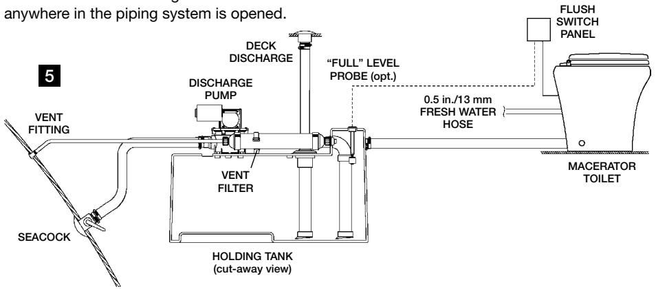

Note
Use cold water only. Include shut-off valve in water line for maintenance purposes.
5.2 Raw water system layout
Domatic macerator toilets can flush on seawater but require a separate pump for this purpose. The pump is activated by the signal from the toilet's flush switch. If the raw water pump draws more than 18 amps of current, a 12 or 24V DC electrical relay must be installed.
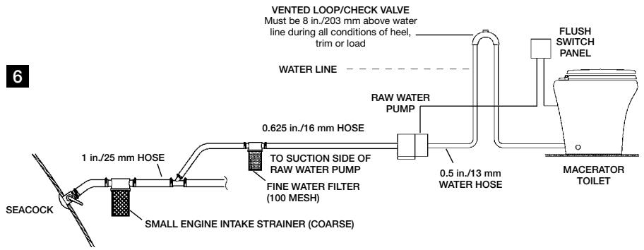

Notes
Use cold water only. Include shut-off valve in water line for maintenance purposes.
Use primary and secondary raw water filters.
Raw water pump MUST NOT be demand-type. Pump is controlled by flush switch.
Install vented loop as shown. It must be equipped with integral check valve that permits air into line to prevent siphoning.
Caution! Hazard of Flooding
If toilet uses raw water for flushing at ANY time, a raw water pump controlled by an automatically operating demand switch MUST NOT be installed. If the onboard water valve or any plumbing connections were to leak, the automatically operated pump would start and could flood the boat. Failure to comply with this warning can cause loss of property and life.
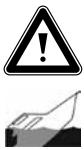
5.3 Toilet system with through-the-floor connections
- Place floor mounting template in desired location (fig. 7). For optimal user comfort, make sure walls or other interior fixtures are at least 11 in. (279 mm) away from centerline of template.
- Center punch all holes and mounting bracket corners through template.
- Remove template from floor. Drill all access and fastener holes as indicated on template. DO NOT drill mounting bracket corners.
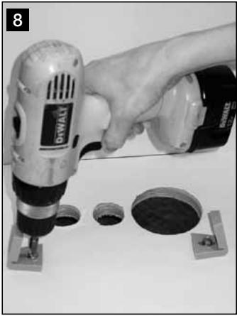
- With long hex-head screws from toilet floor bracket kit, fasten floor brackets with 3/8 in. (10 mm) socket wrench, using corner marks as guides (fig. 8).

Note
Do not completely tighten hex-head screws to floor - allow brackets to slightly slide. Brackets will tighten when fastening toilet to brackets.
- Plan flush switch panel location so that electrical connections and wires cannot get wet.
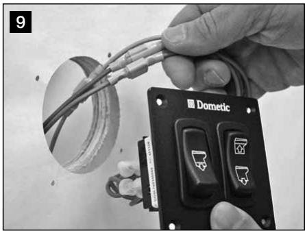
- Use MasterFlush 8100 series toilet wall switch template to mark location of fastener and access holes for wall switch panel. Drill 2.75 in. (70 mm) diameter hole (fig. 9).
- With electrical power off, route 12-gauge or larger stranded copper wire (according ABYC recommendations) from circuit breaker or fuse to wall switch, and from wall switch to toilet. Connect wires to appropriate leads attached to back of wall switch panel with crimp-style wire connectors. (For complete wiring options, refer to wiring diagrams (pp. 11-12).
- Fasten wall switch panel to wall (fig. 9).
- Route wall switch panel wiring to toilet through access hole in floor. Route ground connection wire to toilet. (Provide extra wiring at toilet to easily remove toilet from mounting brackets for future maintenance or service.) Make final wiring connections.
- Route water supply and discharge plumbing to toilet according to system requirements (Section 4.2). Provide extra water supply and discharge hose lengths to assure easy connection to toilet (fig. 13, page 9).
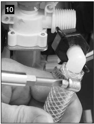
- Connect water valve adapter to flexible water line with hose clamp (fig. 10).
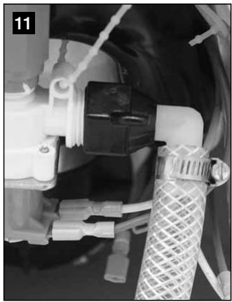
- Securely connect water valve adapter to water valve fitting (fig. 11).
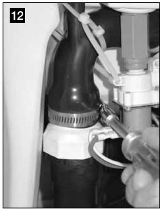
- Loosen band clamp on discharge loop outlet and remove discharge adapter fitting/hose fitting assembly (fig. 12).
- Lubricate discharge fitting assembly and inside end of discharge hose with liquid dishwashing soap. Push discharge fitting assembly into discharge hose and connect with two hose clamps. Be sure to position hose clamp screws 180^ apart from each other (fig. 13). Place toilet near access holes.
- Connect flush switch panel wires to toilet wires (fig. 14) according to appropriate wiring diagram (pp. 11-12). Connect ground wires from toilet as indicated.
- Position toilet over floor brackets and tilt toilet up from back. Push discharge assembly fitting and hose up into discharge loop outlet, and tighten clamp (fig. 14).
- Lower toilet down so that floor brackets show through fastener holes (fig. 15).
- Turn on water supply and electrical power to toilet, and check for leaks. Press "Flush" switch (fig. 4 1, page 2). If leak occurs, tighten connection.
- Insert plastic adapters from Floor Bracket Kit into fastener holes. Fasten toilet to brackets with short screws provided in kit.
- Cover floor bracket screws with plastic covers (fig. 16).
5.4 Toilet system with through-the-wall connections
- To route wiring and plumbing connections through the wall, use floor template to locate the vertical centerline of each hole.
- Loosen band clamp on discharge loop outlet and remove straight discharge hose fitting (fig. 2 5, p. 2) from discharge adapter fitting (fig. 2 4, p. 2).
- Attach discharge elbow fitting (fig. 1 K, p. 2) to discharge adapter fitting.
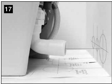
- Place toilet in proper position and mark horizontal centerlines (fig. 17).
- Drill holes sizes as indicated on template.
- Route wiring and plumbing through holes, then follow toilet installation instructions beginning at Section 5.3, step 10.
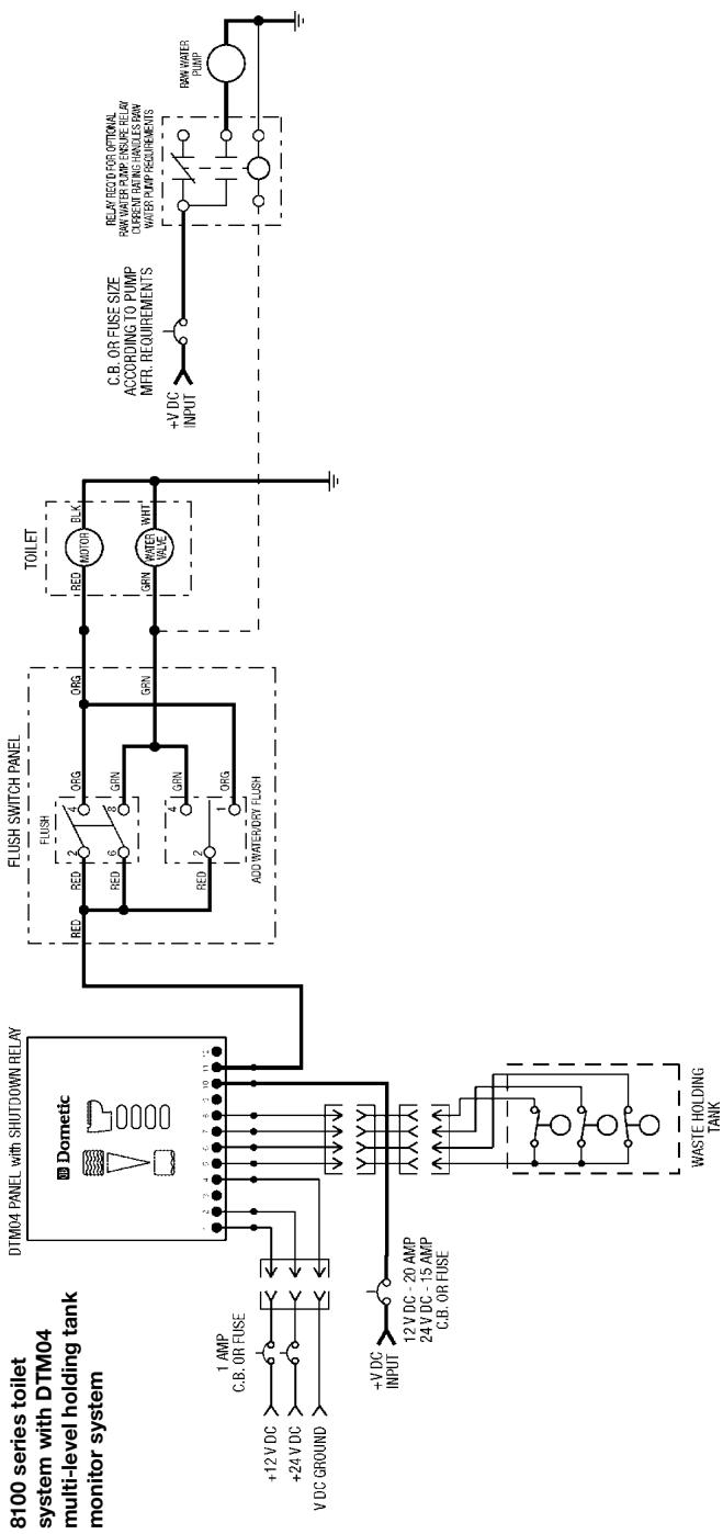
5.5 Toilet system with "full tank" shut-down relay and tank monitor system
Domatic macerator toilets will operate with Domatic's DTM01C Tank Monitor and DTM04 Four-level Tank Monitor systems (available separately). In these installations, the 8100 series toilet receives electrical power through the "full tank" shut-down relay (see Wiring diagrams (pages 11-12.)
- Route input power wires from "full tank" shut-down relay (previously installed according to tank monitor system instructions) to 8100 series Flush Switch Panel.
- Follow toilet installation instructions beginning at Section 5.3, step 10.
5.6 Wiring schematics
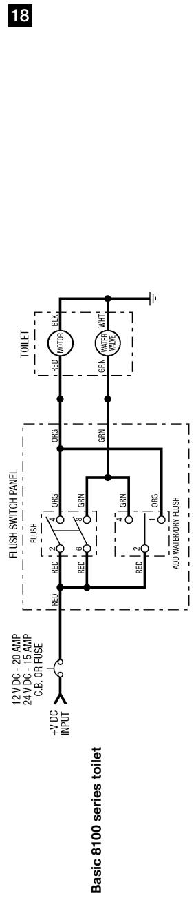
Note

Each toilet must have its own circuit breaker or fuse.
All installation factors must be in accordance with ABYC/ISO electrical standards. Always use crimp-style wire connections. Do not use wire nuts (they corrode).
Caution - Hazard of Shock or Fire

Always use recommended fuse, circuit breaker and wire size. Failure to do so can
cause the loss of property and life.

20
Note
Caution - Hazard of Shock or Fire
Always use recommended fuse, cir cause the loss of property and life.
Always use recommended fuse, circuit breaker and wire size. Failure to do so can
because the loss of property and life.

6 Customer service
There is a strong, worldwide network to assist in servicing and maintaining your sanitation system. For the Authorized Service Center near you, please call from 8:00 a.m. to 5:00 p.m. (ET) Monday through Friday.
You may also contact or have your local dealer contact the Parts Distributor nearest you for quick response to your replacement parts needs. They carry a complete inventory for the Dometic product line.
Telephone: 1800-321-9886 U.S.A. and Canada
330-496-3211 International
Fax: 330-496-3097 U.S.A. and Canada
330-496-3220 International
Web site: http://www.Dometic.com
Inhalt
DE
| Ref. | Dimension |
| A | 83 mm / 3,25 in. |
| B | 83 mm / 3,25 in. |
5 Installation
| Ref. | Afmeting |
| A | 83 mm / 3,25 in. |
| B | 83 mm / 3,25 in. |
Dometic kontrollpanel spoining
(bild 4, sidan 2)
| Ref. | Mätt |
| A | 83 mm / 3,25 in. |
| B | 83 mm / 3,25 in. |
Modeller medlag profil
| Ref. | Mätt |
| A | 381 mm / 15 in. |
| B | 375 mm / 14,75 in. |
| C | 467 mm / 18,375 in. |
| D | 349 mm / 13,75 in. - stolens Höjd |
| E | 356 mm / 14 in. |
| F | 711 mm / 28 in. - med öppet lock |
5 Installation
Forsiktig! Overlapsfare
Hvis toalettet er koblet til NOEN skroggjennomforghingskoblinger, mA ALLE fleksible slanger vare av maritim sanitarkvalitet, og mA festes til EN ELLER ANNEN kobling (som f.eks. de pà stoppekran, luftet slyfe eller toalett) med to slangeklemmer i rustfritt stål på haver tilkobling. Tilkobligene Må kontrolleres regelmessig at de er hele. Hvis du ikke overholder dette, kan det före til oversvömmelse, som igjen kan före til tap av liv og eiendom.

Forsiktig! Overlapsfare
Forsiktig! Overlapsfare
För du begynner Å arbeide på dette Produktet, mä du pASE at all strom til enheten er slätt av og at stoppekranene er i posisjon STENGT aller AV. Hvis du ikke gjør dette, kan det före til oversvömmelse, som igjen kan före til tap av liv og eiendom.

Dometic skylblebryterpanel: pulverbelagt aluminium
4.2 Minimum systemkrav
Dometic skyllebryterpanel
(fig. 4, side 2)
| Ref. | Mål |
| A | 83 mm / 3,25 in. |
| B | 83 mm / 3,25 in. |
Lavprofil modeller
| Ref. | Mål |
| A | 381 mm / 15 in. |
| B | 375 mm / 14,75 in. |
| C | 467 mm / 18,375 in. |
| D | 349 mm / 13,75 in. -setehøyde |
| E | 356 mm / 14 in. |
| F | 711 mm / 28 in. - setelokk opp |
5 Montering
5.1 Systemlayout for ferskvann
Domatic macerator-toaletter kan brukes med et trykksatt ferskvannsystem ombord, med en minimum stromningshestiget pa 9,5 lipm ved toalettet. Ferskvann-spylesystemer ombord inkluderer en vannpumpe som automatisk tar vann fra en vannlagertank när en ventil apnes et sted
i rorsystemet. Domicic-toaletter i 8100-serien har en elektrisk betjent vannventil og integrett kontrollventil for Åhindre forurensning av drikkevann ombord.
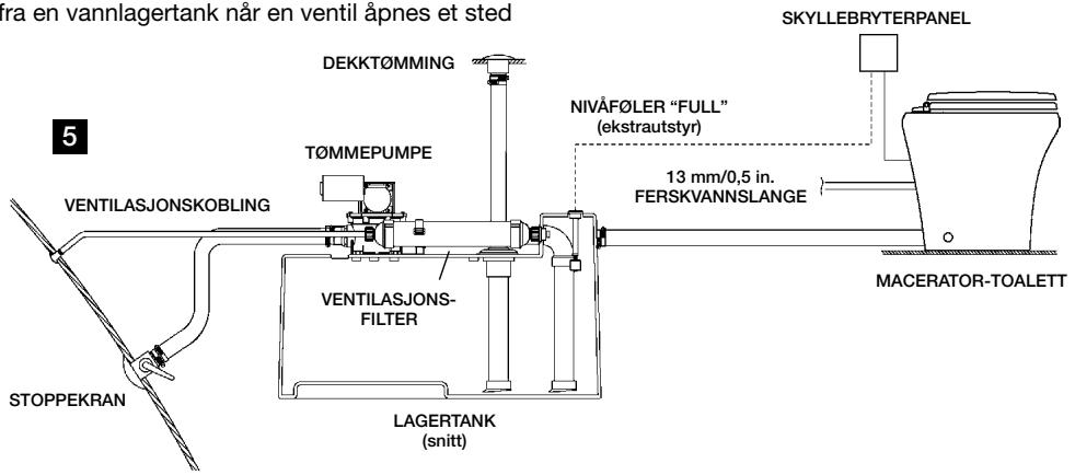

Merk
Bruk kun kaldt vann. Monter stengeventil på vannledningen for vedlikeholdsformål.
5.2 Systemlayout for ubehandlet vann
Domatic macerator-toaletter kan skylle med sjovann, men krever en separat pumpe til dette. Pumpen styres av en skyllebryter. Hvis pumpen for ubehandlet vann trekker mer enn 18 amp strøm, mA det moneres et 12 aller 24 V DC elektrisk reli.
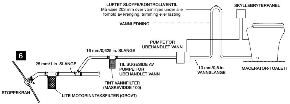

Merk
Bruk kun kaldt vann. Monter stengeventil på vannledningen for vedlikeholdsformål.
- Notes on using the manual
- Caution!
- Note
- General safety instructions
- 2.1Warnings - marine applications
- Caution! Hazard of Flooding
- Caution! Hazard of Shock or Fire
- Components
- Specifications
- Materials
- Minimum System Requirements
- Dimensions (fig. 3, page 2)
- Standard-height models
- Dometic flush switch panel
- Low-profile models
- Installation
- Fresh water system layout
- Raw water system layout
- Notes
- Toilet system with through-the-floor connections
- Toilet system with through-the-wall connections
- Toilet system with "full tank" shut-down relay and tank monitor system
- Wiring schematics
- Caution - Hazard of Shock or Fire
- Customer service
- Inhalt
- DE
- Dometic kontrollpanel spoining
- Modeller medlag profil
- Forsiktig! Overlapsfare
- Minimum systemkrav
- Dometic skyllebryterpanel
- Montering
- Systemlayout for ferskvann
- Merk
- Systemlayout for ubehandlet vann
Brand : DOMETIC
Model : MF-8100 - INSTALLATION
Category : Portable Refrigerator