MPX-210BPM - DJ Controller IMG STAGE LINE - Free user manual and instructions
Find the device manual for free MPX-210BPM IMG STAGE LINE in PDF.
User questions about MPX-210BPM IMG STAGE LINE
0 question about this device. Answer the ones you know or ask your own.
Ask a new question about this device
Download the instructions for your DJ Controller in PDF format for free! Find your manual MPX-210BPM - IMG STAGE LINE and take your electronic device back in hand. On this page are published all the documents necessary for the use of your device. MPX-210BPM by IMG STAGE LINE.
USER MANUAL MPX-210BPM IMG STAGE LINE
63 Before you switch on ...
We wish you much pleasure with your new "img Stage Line" unit. With these operating instructions you will be able to get to know all functions of the unit. By following these instructions false operations will be avoided, and possible damage to you and your unit due to improper use will be prevented.
You will find the English text on pages 9-13.
Booth (Monitor), stereo: . 1 V
Record, stereo: 0,5 V
Kopfhorer, stereo: ≥ 2× 8
Allgemeine Daten
Please unfold page 3. Then you can always see the operating elements and connections described.
Contents
1 Operating Elements and Connections 9
1.1 Front side 9
1.2 Rear side 10
2 Safety Notes 10
3 Applications 10
4 Connection of the Unit 10
5 Operation 11
5.1 Basic settings 11
5.1.1 Basic setting of channels CH 1 to CH 4 ... 11
5.1.2 Basic setting of the microphone channels . 11
5.2 Crossfading function 11
5.3 Beat counter 12
5.3.1 BPM displays 12
5.3.2 Beat Offset display 12
5.4 Mixing of the audio sources 12
5.5 Talkover function 12
5.6 Pre fader listening of the channels via headphones 12
5.7 Monitoring of the music programme via a monitor system 13
6 Specifications 13
1 Operating Elements and Connections
1.1 Front side
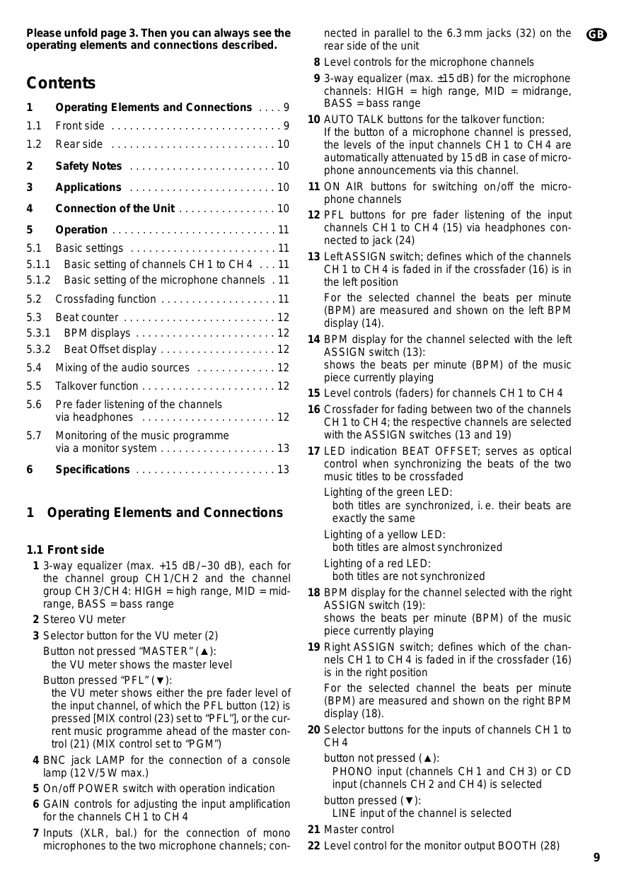
1 3-way equalizer (max. +15 dB/-30 dB), each for the channel group CH1/CH2 and the channel group CH3/CH4: HIGH = high range, MID = mid-range, BASS = bass range
2 Stereo VU meter
3 Selector button for the VU meter (2) Button not pressed "MASTER" () : the VU meter shows the master level
Button pressed "PFL" () : the VU meter shows either the pre fader level of the input channel, of which the PFL button (12) is pressed [MIX control (23) set to "PFL"], or the current music programme ahead of the master control (21) (MIX control set to "PGM")
4 BNC jack LAMP for the connection of a console lamp (12 V/5 W max.)
5 On/off POWER switch with operation indication
6 GAIN controls for adjusting the input amplification for the channels CH1 to CH4
7 Inputs (XLR, bal.) for the connection of mono microphones to the two microphone channels; con
nected in parallel to the 6.3mm jacks (32) on the rear side of the unit
8 Level controls for the microphone channels
9 3-way equalizer (max. ±15 dB) for the microphone channels: HIGH = high range, MID = midrange, BASS = bass range
10 AUTO TALK buttons for the talkover function: If the button of a microphone channel is pressed, the levels of the input channels CH1 to CH4 are automatically attenuated by 15 dB in case of microphone announcements via this channel.
11 ON AIR buttons for switching on/off the microphone channels
12 PFL buttons for pre fader listening of the input channels CH1 to CH4 (15) via headphones connected to jack (24)
13 Left ASSIGN switch; defines which of the channels CH 1 to CH 4 is faded in if the crossfader (16) is in the left position For the selected channel the beats per minute (BPM) are measured and shown on the left BPM display (14).
14 BPM display for the channel selected with the left ASSIGN switch (13): shows the beats per minute (BPM) of the music piece currently playing
15 Level controls (faders) for channels CH 1 to CH 4
16 Crossfader for fading between two of the channels CH 1 to CH 4; the respective channels are selected with the ASSIGN switches (13 and 19)
17 LED indication BEAT OFFSET; serves as optical control when synchronizing the beats of the two music titles to be crossfaded
Lighting of the green LED: both titles are synchronized, i.e. their beats are exactly the same
Lighting of a yellow LED: both titles are almost synchronized
Lighting of a red LED: both titles are not synchronized
18 BPM display for the channel selected with the right ASSIGN switch (19): shows the beats per minute (BPM) of the music piece currently playing
19 Right ASSIGN switch; defines which of the channels CH 1 to CH 4 is faded in if the crossfader (16) is in the right position
For the selected channel the beats per minute (BPM) are measured and shown on the right BPM display (18).
20 Selector buttons for the inputs of channels CH 1 to CH 4
button not pressed () : PHONO input (channels CH1 and CH3) or CD input (channels CH2 and CH4) is selected button pressed () LINE input of the channel is selected
21 Master control
22 Level control for the monitor output BOOTH (28)
23 MIX control for the headphone output (24) and the VU meter (2)
"PFL" (control in the extreme left position):
the pre fader level of the input channel, of which the PFL button (12) is pressed, is monitored via headphones and displayed by the VU meter
"PGM" (control in the extreme right position):
the current music programme is monitored ahead of the master control (21) and displayed by the VU meter
Note: The VU meter must be switched to the headphone output [selector button (3) pressed].
24 6.3 mm jack for the connection of stereo headphones (impedance ≥ 2 × 8 )
25 Level control for the headphone output (24)
1.2 Rear side
26 Mains cable for the connection of the unit to the power supply (230V / 50Hz)
27 Stereo output REC (phono jacks) for the connection of an audio recording unit; the recording level is independent of the position of the master control (21)
28 Stereo monitor output BOOTH (phono jacks) for the connection of a monitor system
29 Stereo output AMP (phono jacks) for the connection of the amplifier
30 Stereo inputs LINE and CD (phono jacks) for the channels CH1 to CH4 for the connection of units with line level outputs (e.g. minidisk recorder, CD player, cassette recorder)
31 Stereo inputs PHONO (phono jacks) for the channels CH 1 and CH 3 for the connection of turntables with magnetic system
32 Inputs (6.3 mm jacks, bal.) for the connection of mono microphones to the two microphone channels; connected in parallel to the XLR jacks (7) on the front plate
33 GND connection for a common grounding point, e. g. for the connected turntables
2 Safety Notes
This unit corresponds to the directive for electromagnetic compatibility 89/336/EEC and the low voltage directive73/23/EEC.
This unit uses dangerous mains voltage (230V) . To prevent a shock hazard, do not open the cabinet. Leave servicing to authorized, skilled personnel only. Furthermore, any guarantee claim expires if the unit has been opened.
Also observe the following items in any case:
The unit is designed for indoor use only. Protect it against humidity and heat (admissible ambient temperature range 0 - 40^ ).
- Do not set the unit into operation and immediately disconnect the mains plug from the mains socket if: 1. there is visible damage to the unit or mains cable,
- a defect might have occurred after a drop or similar accident,
- there are malfunctions.
The unit must in any case be repaired by authorized, skilled personnel.
- A damaged mains cable must only be replaced by the manufacturer or authorized, skilled personnel.
- Never pull the mains plug out of the mains socket by means of the mains cable.
- If the unit is used for purposes other than originally intended, if it is not connected or operated properly or not repaired by authorized, skilled personnel, there is no liability for any possible damage.
- For cleaning use a dry, soft cloth, by no means chemicals or water.
-
If the unit is to be put out of operation definitively, it must be disposed of in a local recycling plant.
-
Important for U.K. Customers!
The wires in this mains lead are coloured in accordance with the following code:
blue = neutral
brown = live
As the colours of the wires in the mains lead of this appliance may not correspond with the coloured markings identifying the terminals in your plug, proceed as follows:
- The wire which is coloured blue must be connected to the terminal in the plug which is marked with the letter N or coloured black.
- The wire which is coloured brown must be connected to the terminal which is marked with the letter L or coloured red.
3 Applications
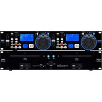
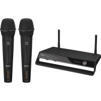
The mixer MPX-210BPM with four stereo channels, two mono microphone channels, and integrated beat counter function is suitable for any desired private or professional DJ applications.
The unit can be placed as a table top unit as well as being installed into a console. It is suitable for rack mounting (482 mm/19") as well. For rack mounting a height of 4 rack spaces (1 rack space = 44.45 mm) is necessary.
4 Connection of the Unit
Prior to the connection of units or changing of existing connections, switch off the mixer.
1) Connect the stereo audio sources to the corresponding phono input jacks of channels CH 1 to CH 4 (white jack L = left channel; red jack R = right channel):
- units with line level output (e.g. mindisk recorder, CD player, cassette recorder) to the jacks CD and LINE (30);
- turntables with magnetic system to the PHONO jacks (31).
The clamping screw GND (33) can be used as common grounding point: connect the grounding connection of the turntable to the clamping screw.
2) Connect mono microphones to the XLR jacks (7) on the front plate or to the 6.3mm jacks (32) on the rear side of the unit.
3) Connect the input of the amplifier to the master output AMP (29).
4) If a monitor system is present, connect the amplifier of the monitor system to the BOOTH output (28).
5) For audio recordings, connect the recording unit to the record output REC (27). The recording level is independent of the position of the master control (21).
6) For an optimum console illumination a gooseneck lamp (12 V/5 W max.) can be connected to the BNC jack LAMP (4), e.g. the lamp GNL-205 of the "img Stage Line" range. The lamp is switched on and off with the mixer.
7) Via stereo headphones the pre fader level of the input channels CH 1 to CH 4 as well as the current music programme ahead of the master control (21) can be monitored (see chapter 5.6). Connect the headphones (impedance ≥ 2× 8 ) to the jack (24).
8) Finally connect the plug of the mains cable (26) to a mains socket (230V / - 50Hz)
5 Operation
Prior to switching on, the output controls MASTER (21) and BOOTH (22) should be set to minimum to avoid strong inrush noise. Then switch on the mixer with the POWER switch (5). The red LED above the switch lights up to indicate that the unit is ready for operation. Then switch on the connected units.
5.1 Basic settings
5.1.1 Basic setting of channels CH1 to CH4
For an optimum level adjustment of the audio sources connected to the input channels CH 1 to CH 4, turn all gain controls (6) and equalizer controls (1) to mid-position first, and set the ASSIGN switches (13 and 19) to "0" (crossfading function switched off).
1) Select the connected signal sources with the selector buttons (20).
Button not pressed (▲):
the PHONO input (for channels CH1 and CH3) or the CD input (for channels CH2 and CH4) is selected.
Button pressed () -LED above the button lights up: the LINE input of the channel is selected.
2) With the master control (21) the total level of all connected audio sources is adjusted. Set the master control to approx. 2/3 of its maximum position, e.g. to position 7.
3) The selector button (3) must not be pressed: with this button position the VU meter (2) shows the stereo output level which is present at the master output AMP (29).
4) To control a channel, set the faders (15) of the remaining channels to minimum and feed the audio signals (test signals or music pieces) to the respective input channel.
5) By means of the VU meter control the level of the channel with the fader. The optimum level is obtained if the 0 dB LEDs of the VU meter shortly light up with music peaks. In case of overload the red LEDs light up.
After the level adjustment the fader should be set to approx. 2/3 of its maximum position so that there is sufficient control range for fading in and out.
6) If the fader is slipped up very much or only very little, the level must be matched by adjusting the input amplification: turn back or turn up the gain control (6) of the channel correspondingly.
The input amplification can be adjusted in an optimum way by the display of the pre fader level. For this purpose press the button (3) to switch the VU meter to the display mode "PFL", slide the MIX control (23) to the left stop to position "PFL", and press the PFL button (12) of the channel: the VU meter now shows the signal level of the channel ahead of the channel fader.
7) Release button (3) to switch the VU meter to the display mode "MASTER" again, and adjust the desired sound with the equalizer controls (1) of the channel - a 3-way equalizer each for the channel group CH1/CH2 and the channel group CH3/CH4: with the three controls the high range (HIGH controls), the midrange (MID controls), and the bass range (BASS controls) can be boosted (max. 15 dB) or attenuated to a large extent (max. 30 dB). If the controls are in mid-position, there is no influence on the frequency response.
Note: Sound adjustments influence the levels. Therefore, after a sound adjustment, check the channel level by means of the level display and correct it, if necessary.
8) Make the level and sound adjustments for the remaining connected input channels as described above.
5.1.2 Basic setting of the microphone channels
To switch on a microphone channel, press the ON AIR button (11) of the channel. The LED next to the button lights up as indication. Set the faders (15) of the input channels CH1 to CH4 to minimum, and adjust the optimal level with the GAIN control (8) of the channel by means of the VU meter (2). Correct the sound for the microphone (max. ± 15dB ) with the equalizer controls (9) - HIGH for the high range, MID for the mid-range, BASS for the bass range.
Make the level and sound adjustments for the second microphone channel in the same way.
5.2 Crossfading function
1)With the two ASSIGN switches select the two channels of the input channels CH1-CH4 to be cross-faded:
With the left ASSIGN switch (13) select the channel to be faded in if the crossfader (16) is slid to the left.
With the right ASSIGN switch (19) select the channel to be faded in if the crossfader is slid to the right.
2) Set the faders (15) of the channels not used to minimum and control the two selected channels with their faders in an optimum way (see chapter 5.1.1).
3) With the crossfader, it is now possible to fade between the two selected channels.
If both channels are to be fed to the outputs at the same time, set the crossfader to the mid-position.
4) With the master control (21) adjust the desired total level which is available at the master output (29). In case of overload [red LEDs of the VU meter (2) light up] reduce the master level.
5.3 Beat counter
The two beat counters of the mixer measure the beats per minute (BPM) for the two channels selected with the ASSIGN switches for the crossfading function. The measured BPM are shown via two displays.
Note: the beat counters only evaluate bass beats which occur four times in succession at approx. the same distance (4 / 4 beat). Music pieces which do not show any clear bass drum line in the 4 / 4 rhythm are not recognized by the beat counters and displayed with wrong values.
5.3.1 BPM displays
Most CD players for disco applications are provided with operating elements to change the speed of the beat (pitch controls). For matching the pitch of one music piece to that of the other via the pitch control when crossfading between the connected audio sources (e.g. two CD players), the two BPM displays of the mixer serve as optical aid.
The left BPM display (14) shows the beats for the channel selected with the left ASSIGN switch (13) and the right BPM display (18) the beats for the channel selected with the right ASSIGN switch (19). If no music piece is playing on the selected channel or if the respective ASSIGN switch is set to "0", the display is [- - -].
The display range is between approx. 90 BPM and 170 BPM. If the BPM of a title are lower, the display is [- - - ] or a wrong value. Higher BPM values are displayed in a divided way (e.g. display 90 BPM in case of an actual value of 180 BPM).
5.3.2 Beat Offset display
To obtain a smooth transition between the titles when crossfading, the beats of both titles have to be synchronized, i.e. they must be exactly the same. Via corresponding operating elements on the CD player the pitch of one title can be matched so that it is synchronized with the second title.
When synchronizing the beats of the two music titles to be crossfaded, the LED indication BEAT OFF-SET (17) serves as optical control:
Lighting up of a red LED:
the two titles are not synchronized
Lighting up of a yellow LED:
the two titles are almost synchronized
Lighting up of the green LED:
the two titles are synchronized
Note: If the BPM of the two titles are far away from each other, the beat offset display does not respond.
5.4 Mixing of the audio sources
1) To mix the connected audio sources, switch off the crossfading function. For this purpose, set the ASSIGN switches (13 and 19) to position "0".
2) Turn up the master control (21) so much that the mixing relation of the audio sources can be adjusted in an optimum way.
3) With the level controls of the input channels adjust the desired volume relation of the audio sources with each other. If a channel is not used, its level control should be set to minimum.
4) By means of the VU meter (2) adjust with the master control the desired total level which is available at the master output (29).
The optimum level is obtained if the 0 dB range of the VU meter shortly lights up with music peaks. In case of overload (red LEDs light up), reduce the output level with the master control and/or the level controls of the input channels.
5.5 Talkover function
The talkover function serves for better intelligibility of microphone announcements during the music programme. To activate the func tion for a microphone channel, press the AUTO TALK button (10) of the channel: if the button is pressed (LED next to the button lights up), the levels of the channels CH 1 to CH 4 are automatically attenuated by 15dB during microphone announcements. To switch off the function, release the button again.
5.6 Pre fader listening (PFL) of the channels via headphones
Via the pre fader listening function each of the input channels CH1 to CH4 can be monitored via headphones connected to the jack (24), even if the corresponding channel fader (15) is set to minimum. Thus, e.g. the desired title on a CD can be selected or the right moment for fading in an audio source can be timed.
Alternatively it is also possible to monitor the music programme currently playing ahead of the master control (21).
1) To monitor an input channel ahead of the channel fader, press the PFL button (12) of the channel (LED above the button lights up) and slide the MIX control (23) to the extreme left position ("PFL").
To monitor the current music programme ahead of the master control, slide the MIX control to the extreme right position ("PGM").
2) To switch the VU meter (2) to the headphone output, press the button (3). Then the VU meter shows the signal selected with the MIX control.
3) With the level control (25) adjust the desired headphone volume.
CAUTION: Do not adjust the headphones to a high volume. Permanent high volumes may damage a person's hearing! The human ear gets accustomed to high volumes which do not seem to be that high after some time. Therefore, do not further increase a high volume after getting used to it.
5.7 Monitoring of the music programme via a monitor system
The music programme currently playing can be monitored ahead of the master control (21) via a monitor system connected to the BOOTH jacks (28). Adjust the level for the monitor system with the BOOTH control (22).
6 Specifications
Inputs
Mic, mono: 1.5mV
Phono, stereo: 3mV
Line and CD, stereo: . . . 130 mV
Outputs
Amp (Master), stereo: . . . 1 V
Booth (monitor), stereo: .1 V
Record, stereo: 0.5 V
Headphones, stereo: ... ≥ 2 x 8Ω
General information
Frequency range: 20-20000 Hz
THD: 0.1%
S/N ratio: >53 dB
Equalizer CH1 to CH4
bass: +15 dB, -30 dB/50 Hz
mid: +15 dB, -30 dB/1 kHz
high: +15 dB, -30 dB/10 kHz
Equalizer Mic
bass: ±15 dB/50 Hz
mid: ±15 dB/1 kHz
high: ±15 dB/10 kHz
Talkover (automatic): . . . -15 dB
Connection for
console lamp: 12 V/5 W max., BNC
Ambient temperature: .0-40°C
Power supply: 230 V~/50 Hz
Consumption: 10 VA
Dimensions: 482 x 178 x 105 mm, 4 rack spaces
Weight: 3.8 kg
According to the manufacturer.
Subject to change.

Table des matieres
Graves: ±15 dB/50 Hz
Médiums: ±15 dB/1 kHz
Aigus: ±15 dB/10 kHz
Amp (master), stereo: 1 V
Booth (monitor), stereo: . 1 V
Record, stereo: 0,5 V
Cuffia, stereo: ≥ 2 × 8