
25C5030 - Drill KINZO - Free user manual and instructions
Find the device manual for free 25C5030 KINZO in PDF.
| Product type | Multifunction drill (compact DIY tool) |
| Brand | KINZO |
| Model | 25C5030 |
| Supply voltage | 230 V ~ |
| Mains frequency | 50 Hz |
| Power consumption | 135 W |
| No-load speed | 10,000 – 33,000 min⁻¹ |
| Collet chuck capacity | 1.0 – 3.0 mm |
| Weight | 0.5 kg |
| Sound pressure level (LpA) | 77.5 dB(A) |
| Sound power level (LWA) | 90.5 dB(A) |
| Vibration (RMS value) | < 2.5 m/s² |
| Main functions | Drilling, grinding, polishing, cutting, sanding, milling, chiseling, deburring |
| Speed adjustment | Continuous speed control wheel for maximum speed |
| Electrical safety | Shaft lock button, emergency stop via on/off switch |
| Maintenance | Regular cleaning of ventilation slots; check and replace carbon brushes |
| Included accessories | Chuck, wrench, flexible shaft (described in manual), collet chucks, grinding wheels, abrasive discs, brushes |
| Repairability | Removable brush holders for carbon replacement; spare parts available |
| Compliance standards | EN 55014-1, EN 55014-2, EN 50144-1, EN 50144-2-1, EN 61000-3-2, EN 61000-3-3 |
| Warranty | According to conditions enclosed with the manual |
Frequently Asked Questions - 25C5030 KINZO
User questions about 25C5030 KINZO
0 question about this device. Answer the ones you know or ask your own.
Ask a new question about this device
Download the instructions for your Drill in PDF format for free! Find your manual 25C5030 - KINZO and take your electronic device back in hand. On this page are published all the documents necessary for the use of your device. 25C5030 by KINZO.
USER MANUAL 25C5030 KINZO
visitus at www.KINZO.COM
NL GEBRUIKSAANWIJZING
MODE D'EMPLOI
GEBRAUCHSANWEISUNG
E MANUAL DE INSTRUCCIONES
P MANUAL DE INSTRUÇÉS
INSTRUZIONE PER L'USO
GBINSTRUCTIONMANUAL
N INSTRUKSJONSHANDBOK
ANVANDARMANUAL
DK INSTRUKTIONSBOG
KAYTTOOHJE
GR ODHIGE XPHSEΩ
RUS PYKOBOIDCTBO IOKCINJYATAUIN
PL INSTRUKCJA OBSLUGI
H KEZELESI UTASITAS
CZ NAVOD K POUZITI
0 MANUAL DE INSTRUCTIUNI
SK NAVOD NA OBSLUHU
TR KULLANMA TALIMATLARI
25C5030

Nederland 6
Francais 12
Deutsch 19
Espanol 26
Portugues 32
Italiano 39
English 45
Norsk 52
Svenska 59
Dansk 65
Suomi 71
Elambdaika 77
Pycckn y3bIK 84
Polski 92
Magyar 98
Cesky 105
Roman 111
Slovensky 118
Türkce 124
25C5030


25C5030
3


25C5030
5
HOBBYMACHINE 25C5030
WAARSCHUWING
73/23/CEE, 93/68/CEE, 89/336/CEE, 98/37/EC
M. Kinsbergen, Director
Kinzo B.V., Postbus 735, 6710 BS Ede, Holanda
FERRAMENTA COMPACTA PARA PASSATEMPO 25C5030
AVISO
73/23/CEE, 93/68/CEE, 89/336/CEE, 98/37/EC
Read this manual carefully before using the machine, for your own safety.
SAFETY INSTRUCTIONS
When using the machine, always observe the enclosed safety instructions as well as the additional safety instructions.
25C5030
45


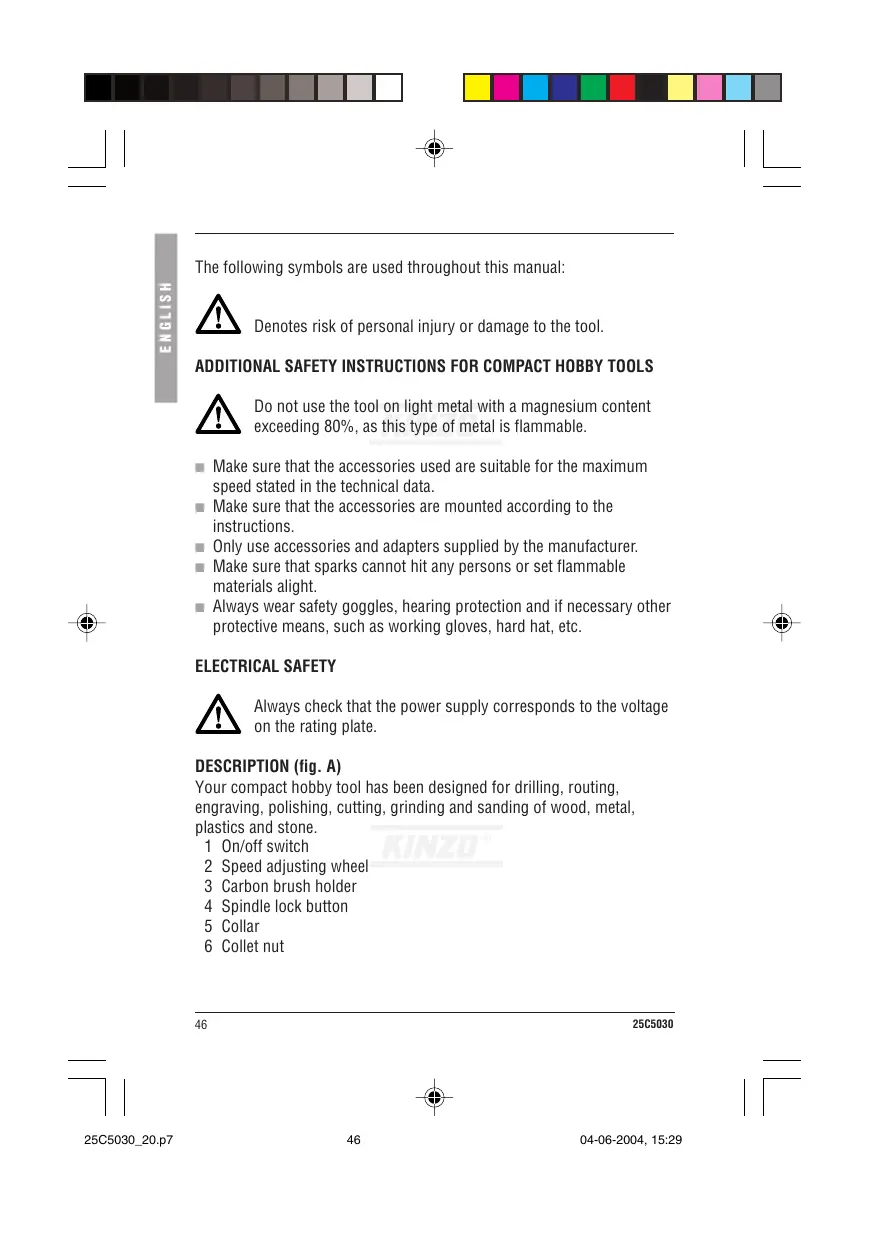
The following symbols are used throughout this manual:

Denotes risk of personal injury or damage to the tool.
ADDITIONAL SAFETY INSTRUCTIONS FOR COMPACT HOBBY TOOLS

Do not use the tool on light metal with a magnesium content exceeding 80% , as this type of metal is flammable.
Make sure that the accessories used are suitable for the maximum speed stated in the technical data.
Make sure that the accessories are mounted according to the instructions.
Only use accessories and adapters supplied by the manufacturer.
Make sure that sparks cannot hit any persons or set flammable materials alight.
Always wear safety goggles, hearing protection and if necessary other protective means, such as working gloves, hard hat, etc.
ELECTRICAL SAFETY

Always check that the power supply corresponds to the voltage on the rating plate.
DESCRIPTION (fig. A)
Your compact hobby tool has been designed for drilling, routing, engraving, polishing, cutting, grinding and sanding of wood, metal, plastics and stone.
1 On/off switch
2 Speed adjusting wheel
3 Carbon brush holder
4 Spindle lock button
5 Collar
6 Collet nut
46
25C5030
Mounting an accessory (fig. A & B)
- Keep the spindle lock button (4) depressed.
Use the spanner (7) to slacken the collet nut (6).
Insert the shaft of the accessory into the collet.
Use the spanner to tighten the collet nut.
Release the spindle lock button.
In order to remove the accessory, proceed in reverse order.

Before mounting an accessory, always unplug the tool.
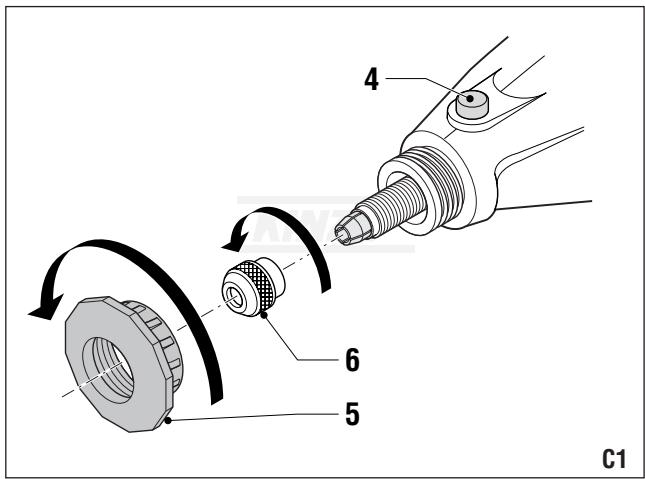
Using the flexible spindle (fig. C1 - C4 & D)
To mount the flexible spindle, proceed as follows:
- Keep the spindle lock button (4) depressed.
Loosen the collet nut (6).
- Successively remove the collet nut (6) and the collar (5).
Remove the collet nut from the flexible spindle and fit it onto the tool.
Insert the end of the flexible spindle into the collet nut.
Tighten the collet nut.
Release the spindle lock button.
Fit the collar of the flexible spindle onto the tool. Tighten the collar.
Fit the collet nut (6) onto the flexible spindle.
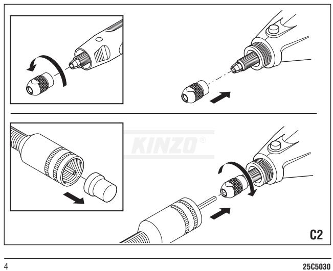
To mount an accessory, proceed as follows:
Position the key (8) in the recess to fix the collet.
Loosen the collet nut (6).
Insert the shaft of the accessory into the collet.
Tighten the collet nut.
Remove the key.
In order to remove the accessory, proceed in reverse order.

Before mounting an accessory, always unplug the tool.
Replacing the collet (fig. A & B)
- Keep the spindle lock button (4) depressed.
Use the spanner (7) to slacken the collet nut (6).
25C5030

Remove the collet nut and the old collet (9).
Place the new collet.
Replace the collet nut.
Release the spindle lock button.

Always unplug the tool before replacing the collet.
Switching on and off (fig. A)
To switch the machine on, set the on/off switch (1) to 'I'.
To switch the machine off, set the on/off switch (1) to '0'.
Adjusting the speed (fig. A)
This machine has been fitted with an adjusting wheel (2) for the maximum speed.
Turn the adjusting wheel (2) as indicated on switch (1) to set the maximum speed.

Choose a low speed for working wood and plastics.
Also choose a low speed for polishing.
Polishing (fig. A & B)
A polishing wheel is used for polishing metal and plastic workpieces.
A mandrel is used for mounting a polishing wheel.
Place the mandrel (14) in the collet nut (6).
Place a polishing wheel (19) on the screw.
Cutting and sanding (fig. A & B)
A cutting disc is used for cutting metal, plastic, wooden and stone workpieces. A sanding disc is used for sanding wooden and plastic workpieces. A mandrel is used for mounting a cutting disc or sanding disc.
Place the mandrel (15) in the collet nut (6).
Loosen the screw on the mandrel.
Place a cutting disc (21) or sanding disc (20) on the screw.
Place the screw on the mandrel and tighten it.

Deburring (fig. A & B)
A grinding disc for deburring is used for removing burrs from metal workpieces. A mandrel is used for mounting a grinding disc for deburring.
Place the mandrel (15) in the collet nut (6).
Loosen the screw on the mandrel.
Place a grinding disc for deburring (22) on the screw.
Place the screw on the mandrel and tighten it.
Drilling (fig. A & B)
A drill bit is used to drill holes in plastic, wooden and stone workpieces.
Place a drill bit (10) in the collet nut (6).
Routing (fig. A & B)
A router bit is used for grooving and for routing figures in plastic, wooden and metal workpieces.
Place a router bit (13) in the collet nut (6).
Engraving (fig. A & B)
An engraving needle is used for engraving figures in metal workpieces.
Place an engraving needle (16) in the collet nut (6).
Grinding and sanding (fig. A & B)
A grinding stone is used for grinding metal, plastic, wooden and stone workpieces. A sanding band is used for sanding wooden and plastic workpieces.
- Place a grinding stone (11) or sanding band with mandrel (12) in the collet nut (6).
Replacing a sanding band (fig. B)
A sanding band must be replaced when showing signs of wear.
Remove the old sanding band from the mandrel.
Place the new sanding band (18) on the mandrel.
Using the grinding stone (fig. B)
Use the grinding stone (17) for removing burrs and other irregularities on the workpiece.
Using the steel wire brush (fig. B)
Use the steel wire brush (23) for cleaning, removing rust and polishing on hard metal.
Checking and replacing the carbon brushes (fig. A)
The carbon brushes must be checked on a regular basis.
Remove the carbon brush holders (3) and clean the carbon brushes.
In case of wear, replace both carbon brushes at the same time.
Mount the carbon brush holders.
After mounting new carbon brushes, let the machine run at no load for 15 minutes.

Use only the correct type of carbon brushes.
CLEANING AND MAINTENANCE
The machine does not require any special maintenance.
Regularly clean the ventilation slots.
TECHNICAL DATA
| 25C5030 | ||
| Mains voltage | V | 230 |
| Mains frequency | Hz | 50 |
| Power input | W | 135 |
| No load speed | min-1 | 10,000 - 33,000 |
| Collet size | mm | 1.0-3.0 |
| Weight | kg | 0.5 |
Level of sound pressure measured according to EN 50144:
| 25C5030 | ||
| LpA (sound pressure) | dB(A) | 77.5 |
| LWA (acoustic power) | dB(A) | 90.5 |

Take appropriate measures for the protection of hearing.
50
25C5030

Weighted root mean square acceleration value according to EN 50144:
25C5030
<2.5m/s²
GUARANTEE
Refer to the enclosed guarantee conditions for the terms and conditions of guarantee.
ENVIRONMENT
Should your machine need replacement after extended use, do not put it in the domestic waste but dispose of it in an environmentally safe way.
DECLARATION OF CONFORMITY
C
Kinzo B.V. declares that the machines:
Compact hobby tool 25C5030
have been designed in compliance with the following standards:
EN 55014-1, EN 55014-2, EN 50144-1, EN 50144-2-1, EN 61000-3-2,
EN 61000-3-3
and
in accordance with the following directives:
73/23/EEC, 93/68/EEC, 89/336/EEC, 98/37/EC
Ede, The Netherlands, June 2004

M. Kinsbergen
Director
Kinzo B.V., Postbus 735, 6710 BS Ede, The Netherlands
25C5030
51
IMPORTANT (FOR UK ONLY)
If the moulded 3 pin plug attached to this unit is damaged and needs replacing, it is important that it is correctly destroyed and replaced by an approved BS 1363/5A fused plug and that the following wiring instructions are followed.
The wires in this mains lead are coloured in accordance with the following code:
blue neutral
brown live
As the colours of the wires in the mains lead of this unit may not correspond to the coloured markings identifying the terminals in your plug, proceed as follows:
The wire which is coloured blue must be connected to the terminal which is marked with the letter N or coloured black.
The wire which is coloured brown must be connected to the terminal which is marked with the letter L or coloured red.
KOMPAKT HOBBYVERKTØY 25C5030
ADVARSEL
RENGJØRING OG VEDLIKEHOLD
73/23/EOK, 93/68/EOK, 89/336/EOK, 98/37/EC
Ede,Oλλαδiə,Iouvioς 2004

M. Kinsbergen,
Director
Kinzo B.V., Postbus 735, 6710 BS Ede, The Netherlands
KOMПАКTHьИ NHCTPYMEHTДЛЯ РУКОДELЯ 25C5030
BHIMAHNE
B cênx 630nachoctn BnHMaTeIbHo npouHTaTe pyKOBOcTBO do NJIb3OBAHnI CTAHKOM.
PYKOBOCTBO NO TEXHNIKE BE30NACHOCTN
Bo Bpem noIb3OBAHncaTahKOM Bcergda co6JIoJaai Te npinlaraemoe pykoBOcTBo nTo texHnke 6e3OnacHOCTn, a taXke IOnOHInTeJbHbIe npEynpeJnteJbHbIe MepbI 6e3OnacHOCTn.
84
25C5030

BpykoBOIDCTBE npimHeHIOCTcneDyOuIe CNMBoJIb:

Yka3bIbaeHa npck NOBpeXdHnIIOeI IIOI O6OpyOboHnI.
UcTaHOBnTe CBePJo (10) BraKy ZaHROBOro NaTPOHa (6).
ΦacoHHoe Φpe3epoBaHne (pnc. A & B)
Φpe3epHna rOJOBka npImeHЯETcI nI Hape3aHnI pa3OB n KaHabOK, a TAKXe IJIy faoCHHO rΦpe3epoBaHnI 3aROTOBOK n3 pJIaCTMaCCbI, dpeBecInbI n MeTaNla.
UcTaHOBnTe Φpe3epHyIO rOIOBky (13) BraKy cAnroBOrO naTPOHa (6).
Гравиорвka (pnc. A & B)
CKOHCTpynpoBaH B COOTBeTCTBm CO CJIeDyIOUIMN CTaHdapTaM:
EN 55014-1, EN 55014-2, EN 50144-1, EN 50144-2-1,
EN 61000-3-2, EN 61000-3-3
25C5030
91

#
COrIaCHO CJIeIyUOuIM HOpMaTINBbIM DOKyMeHTaM: 73/23/EEC,93/68/EEC,89/336/EEC,98/37/EC
3e, HneplaHbI, HOB 2004

73/23/EEC, 93/68/EEC, 89/336/EEC, 98/37/EC
104
25C5030
Ede, Hollandia, 2004. junius

73/23/EEC, 93/68/EEC, 89/336/EEC, 98/37/EC
Ede, Nizozemi, Červen 2004

M. Kinsbergen
Reditel
Kinzo B.V., Postbus 735, 6710 BS Ede, The Netherlands
MASINA-UNEALTÁ COMPACTÁ PENTRU AMATORI 25C5030
ATENTIE
73/23/EEC, 93/68/EEC, 89/336/EEC, 98/37/EC
25C5030
117

Ede,Olanda,Iunie 2004

M. Kinsbergen
Director
Kinzo B.V., Postbus 735, 6710 BS Ede, Olanda
KOMPAKTNY NASTROJ PRE KUTOLOV 25C5030
UPOZORNENIE
73/23/EEC, 93/68/EEC, 89/336/EEC, 98/37/EC
Ede, Holandsko, Jun 2004

M. Kinsbergen
Riaditel'
Kinzo B.V., Postbus 735, 6710 BS Ede, Holandsko
AMATÖRLER İÇİN KOMPAKT ALETLER
25C5030
DIKKAT
73/23/EEC, 93/68/EEC, 89/336/EEC, 98/37/EC
Ede, Holland, haziran 2004

M. Kinsbergen
Direktör
Kinzo B.V., Postbus 735, 6710 BS Ede, Holland
25C5030
131


- HOBBYMACHINE 25C5030
- WAARSCHUWING
- FERRAMENTA COMPACTA PARA PASSATEMPO 25C5030
- AVISO
- SAFETY INSTRUCTIONS
- ADDITIONAL SAFETY INSTRUCTIONS FOR COMPACT HOBBY TOOLS
- ELECTRICAL SAFETY
- DESCRIPTION (FIG. A)
- MOUNTING AN ACCESSORY (FIG. A & B)
- USING THE FLEXIBLE SPINDLE (FIG. C1 - C4 & D)
- REPLACING THE COLLET (FIG. A & B)
- SWITCHING ON AND OFF (FIG. A)
- ADJUSTING THE SPEED (FIG. A)
- POLISHING (FIG. A & B)
- CUTTING AND SANDING (FIG. A & B)
- DEBURRING (FIG. A & B)
- DRILLING (FIG. A & B)
- ROUTING (FIG. A & B)
- ENGRAVING (FIG. A & B)
- GRINDING AND SANDING (FIG. A & B)
- REPLACING A SANDING BAND (FIG. B)
- USING THE GRINDING STONE (FIG. B)
- USING THE STEEL WIRE BRUSH (FIG. B)
- CHECKING AND REPLACING THE CARBON BRUSHES (FIG. A)
- CLEANING AND MAINTENANCE
- TECHNICAL DATA
- GUARANTEE
- ENVIRONMENT
- DECLARATION OF CONFORMITY
- C
- IMPORTANT (FOR UK ONLY)
- KOMPAKT HOBBYVERKTØY 25C5030
- ADVARSEL
- RENGJØRING OG VEDLIKEHOLD
- KOMПАКTHЬИ NHCTPYMEHTДЛЯ РУКОДELЯ 25C5030
- BHIMAHNE
- PYKOBOCTBO NO TEXHNIKE BE30NACHOCTN
- ΦACOHHOE ΦPE3EPOBAHNE (PNC. A & B)
- ГРАВИОРВKA (PNC. A & B)
- MASINA-UNEALTÁ COMPACTÁ PENTRU AMATORI 25C5030
- ATENTIE
- KOMPAKTNY NASTROJ PRE KUTOLOV 25C5030
- UPOZORNENIE
- AMATÖRLER İÇİN KOMPAKT ALETLER
Brand : KINZO
Model : 25C5030
Category : Drill