USER MANUAL MIRABILIA FALMEC
INSTRUCTIONS BOOKLET
Dear Sir/Madam, congratulations!
You have purchased a prestigious range hood of guaranteed quality. For best results, we suggest that you carefully follow the operating and maintenance instructions provided in this booklet; in addition, to order spare charcoal filters, use the special coupon on the cover.
3. PANNELLO REMOVIBLE
Square halogen light

This instruction booklet must be kept together with the appliance for future reference. If the appliance is sold or consigned to other parties, check that the booklet is supplied with it, to ensure that the new user has the correct information on the operation of the range hood and is aware of the warnings. These warnings have been provided for the your safety and the safety of others. As a result, please read them carefully before installing and operating the appliance.
This appliance is not intended for use by young children or infirm persons unless they have been adequately supervised by a responsible person to ensure that they can use the appliance safely. Young children should be supervised to ensure they do not play with the appliance.
The appliance must be installed by qualified personnel, in accordance with the standards in force. If the supply cord is damaged, it must be replaced by the manufacturer, its service agent or similarly qualified persons in order to avoid a hazard. Any modifications that may be required to the electrical system for the installation of the range hood must only be made by qualified electricians.
It is dangerous to modify or attempt to modify the characteristics of this system. In the event of malfunctions or if repairs are required to the appliance, do not attempt to solve the problems directly.
Repairs performed by unqualified persons may cause damage. For all repair and other work on the appliance, contact an authorised service/spare parts centre.
Always check that all the electrical parts (lights, exhaust device), are off when the appliance is not being used. Read the entire instruction booklet before performing any operations on the range hood.
The range hood must only be used for the exhaust of cooking fumes in home kitchens. The manufacturer disclaims all liability for any other use of the appliance.
The maximum weight of any object placed above the hood, or hung to it (if possible) must not exceed 1,5 kilos. After installing the stainless steel hood, clean it in order to remove any residue of the protective glue, and stains of grease or oil. The manufacturer recommends its cleaning cloth available for purchase. The manufacturer accepts no liability in case of damage caused by the use of different detergent types.

TECHNICAL SPECIFICATIONS
The technical data pertaining to the electric appliance The technical specifications of the appliance are shown on the rating plates located inside the range hood.
(Section reserved for qualified installers of the range hood)
Minimum distance: distance between the pan supports of the cooker and the bottom-most section of the hood. When the hood is positioned above a gas equipment this minimum distance must be at least 65~cm (see picture C1/C2) or even more, if this is specified in the instructions for use of the gas cooker. In the outside exhaust version, the diameter of the fume discharge duct must be no smaller than the range hood connection.
In the horizontal sections, the duct must slope slightly (around 10% ) upwards, so as to better convey the air outside of the room.
Avoid using angled pipes, make sure that the pipes are at least of the minimum length.
Comply with the current regulations on air discharge into the atmosphere. If a boiler, stove, fireplace, etc. that uses gas or other fuels is being used at the same time, make sure the room where the fumes are extracted is well ventilated, in compliance with the current regulations.
Mounting instruction: see section "O" of the booklet.

ELECTRICAL CONNECTIONS
(Section reserved for qualified installers)
WARNING!
Before doing any work inside the range hood, disconnect the appliance from the mains power supply.
Check that the wires inside the range hood are not disconnected or cut; if this is the case, contact your nearest service centre. The electrical connections must be performed by qualified personnel.
The connections must be performed in compliance with the legal standards in force. Check that the relief valve and the electrical system are able to support the load of the appliance (see the technical specifications in point B).
Some types of appliance are supplied with a cable without plug; in this case, "standardised" plugs must be used, keeping in mind that:
- the yellow-green wire must be used for the earth,
- the blue wire must be used for the neutral,
- the brown wire must be used for the phase; the cable must not come into contact with hot parts (over 70^ ).
- fit a plug that is suitable for the load to the power cable, and connect it to a suitable power outlet.
For appliances that come supplied with cable and plug please ensure they are plugged into a circuit suitable for this appliance.
Please refer to a qualified person. (See technical specifications in point B).
The manufacturer declines all liability if the safety standards are not observed.

RANGE HOOD WITH OUTSIDE
DISCHARGE (exhaust)
In this version, the fumes and steam from the kitchen are conveyed outside through an exhaust duct.
The exhaust conveyor that protrudes from the upper part of the range hood must be connected to a duct that carries the fumes and steam outside. In this version, the charcoal filters, if fitted, should be removed; to do this, see the instructions in point F. There must be adequate ventilation of the room when the range hood is used at the same time as appliances burning gas or other fuels, according to the standard.
Deviation for Germany:
When the range hood and appliances supplied with energy other than electricity are simultaneously in operation, the negative pressure in the room must not exceed 4 Pa (4x10 E-5 bar).

RECIRCULATING RANGE
HOOD (with filter)
In this version, the air passes through charcoal filters for purification, and is then recirculated back into the kitchen.
Check that the charcoal filters are fitted to the motor, and if not, install them as described in the instructions in point H.
If the hood is of filtering type, remove the non-return valve fitted at the motor's outlet.

For maximum efficiency, the third speed should be used when there are strong odours or a lot of steam, the second speed in normal conditions, and the first speed for keeping the air clean with minimum energy consumption. The range hood should be switched on when starting to cook, and left on until the odours disappear.

OPERATION
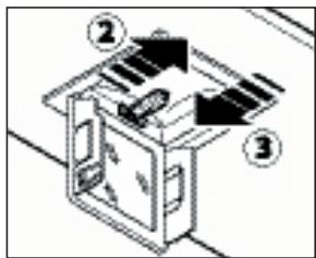
1. ELECTRONIC CONTROL PANEL
Light pushbutton

- ON: light on (the pushbutton is lit);
- OFF: light off;
Press to reduce motor speed
Speed 1, 2 and 3 are indicated by the number of LEDs that light up (excluding the light and the timer LEDs).
Press to increase motor speed
Speed 1, 2 and 3 are indicated by the number of LEDs that light up (excluding the light and the timer LEDs). (In the 4-speed version the pushbutton + blinks. The fourth speed remains on for a set duration of time. After 15 minutes the motor returns to the third speed).
Function: it turns hood motor on and off.
The function "desired speed" enables to start the motor at the speed that was selected before the hood was last turned off.
Optional: version with remote control (some versions only).
WARNING:
Install the hood away from sources of electromagnetic waves, as these could affect the correct operation of the electronic system.
Maximum operating distance: 5 metres. The maximum operating distance could be less than 5 metres in case of electromagnetic interference by other equipment.
Light pushbutton on remote control: light on/off.
- and + pushbutton: increase/decrease speed (to start the motor press either the + or the - pushbutton).
Timer pushbutton: see instructions below.
- This function allows the automatic turning off of the hood after running for 15 minutes at the speed previously set (the pushbutton shows a flickering light).
- After about 30 hours of running the pushbutton indicates the need for washing the metal filters (the pushbutton shows a solid red light). To disable the alarm press the pushbutton for a few seconds until the red light turns off. Then turn the hood off and on again to check that the alarm has disappeared.
2. DIMMER
At the bottom of the hood there is a dimmer for the adjustment of the ambient lights.
a) Knob dimmer: turn the knob clockwise to increase light intensity and anticlockwise to decrease it. To turn the light off turn the knob anticlockwise till the OFF click. To turn it on, turn the knob clockwise till the ON click.
b) Soft-touch dimmer: keep the button pressed to increase or decrease light intensity.
c) Dimmer with functions integrated in the control panel: with the motor turned off and by holding down the light button on the control panel for a while (2 seconds) you automatically decide on the mode of the light intensity (incandescent light globe). By pressing on + and on - you can adjust the intensity of the light. With the motor running, the prolonged pressing of the button down, will turn the atmosphere light on or off.
To replace the incandescent light bulb:
1) make sure that the hood is disconnected from the power supply;
2) remove the decorative glass (refer to section O);
3) fit a new light bulb of the same model (max. 25W);
4) replace the decorative glass (refer to fig. O5).
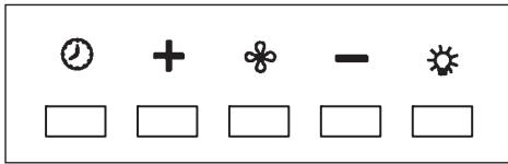
Open the panel (see fig. H3). Use handle A to remove the metal grease filter.
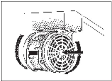
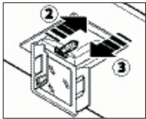
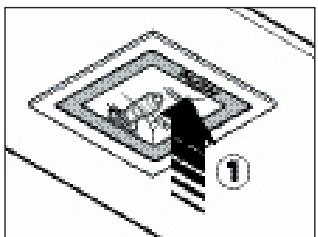
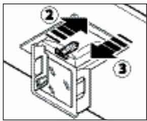
2. CHARCOAL FILTERS
To replace the charcoal filters, proceed as follows: remove the metal filters as described above. The two filters located at the ends of the motor can now be easily accessed.
To install the new filters see picture.
To order new filters, use the coupon enclosed with this booklet or provided by the distributor.
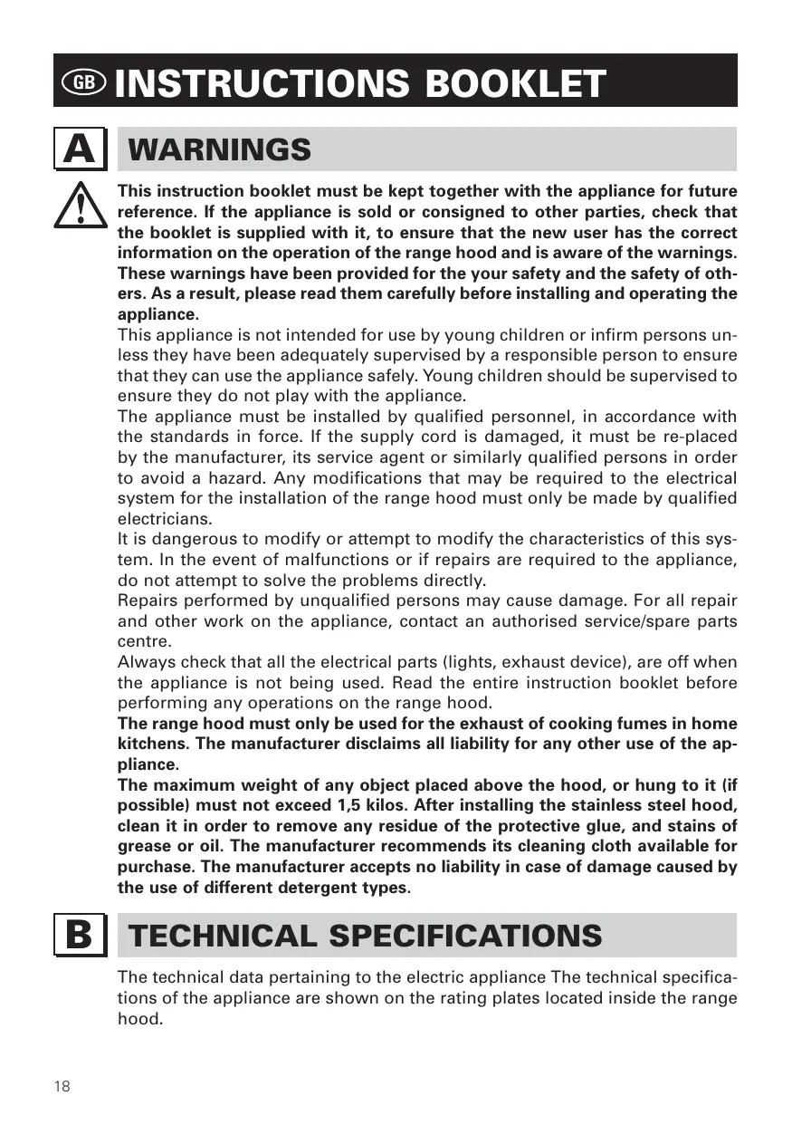
3. REMOVABLE PANEL
Follow the instructions on fig. H3 to remove the panel.

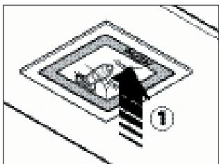
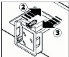
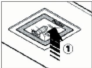
LIGHTING ASSEMBLY AND REPLACEMENT
SPOTLIGHT
How to replace a square halogen light:
a) Check that the equipment is disconnected from the power supply.
b) Open the panel completely till 90^ (see figure) pressing the PUSH button
c) Replace the lamp with a similar one (halogen, max 20 W, 12 Volt, G4 connection).
d) Close the panel. If the panel does not close correctly repeat the operation at point b.
Square halogen light

MAINTENANCE AND CLEANING
Constant maintenance ensures the correct operation and efficiency of the appliance over time. Special attention should be paid to the metal grease-trapping filters and the charcoal filters. Frequent cleaning of the filters and their supports will ensure that fats and grease do not accumulate on the range hood, with the consequent risk of fire.
These trap the fat and grease particles suspended in the air, and therefore should be washed every month in hot water and detergent, without bending them. Wait until they are completely dry before repositioning them.
To remove and replace these filters, see the instructions in point H1. This operation should be performed at regular intervals.
2. CHARCOAL FILTERS
These trap the odours present in the stream of air that passes through them. The air is purified by passing a number of times through the filters and being recirculated into the kitchen. The charcoal filters cannot be cleaned, and should be replaced on average every 3-4 months (according to use). To replace the charcoal filters, see the instructions in point H2.
3. CLEANING THE OUTSIDE OF THE APPLIANCE
The aside of the range hhod should be cleaned using a damp cloth and neutral liquid detergent or denatured alcohol.
In case of fingerprint-less finish (fasteel) clean only with water and neutral soap using clean with a soft cloth, rinse and wipe dry thoroughly. Do not use products that contain abrasive substances, rough cloths or cloths specifically designed for cleaning steel. Using abrasive substances or rough cloths will inevitably damage the finish of steel. The steel surface will be irrevocably damaged if the instructions above are not complied with.
Keep these instructions together with the instructions for use of your hood. The manufacturer accepts no liability for any damage caused by non-compliance with the instructions above.
4. CLEANING THE INSIDE OF THE APPLIANCE
The electrical parts or parts of the motor assembly inside the range hood must not be cleaned using liquids or solvents.

Do not use abrasive products. All the above operations must be performed after having disconnected the appliance from the mains power supply.

The electrical system features an earth connection in compliance with international safety standards; furthermore, it is compliant with the European standard for electromagnetic compatibility.
Do not connect the appliance to flues (from boilers, fireplaces, etc.). Make sure the mains voltage corresponds to the values on the rating plate located inside the range hood. The minimum safety distance between the cooktop and the range hood must be at least 65~cm .
Never cook on "open" flames under the range hood.
Check deep-fryers during use: superheated oil may be flammable.
- Ensure there is adequate ventilation of the room when the rangehood is used at the same time as appliances burning gas or other fuels.
- Do not flambe under the rangehood
- The exhaust air must not be discharged into a flue which is used for exhausting fumes from appliances burning gas or other fuels.
- Ensure that all regulations concerning the discharge of exhaust air have been fulfilled before you use the appliance.

Before performing any cleaning or maintenance operations, disconnect the appliance by unplugging it or using the main switch. The manufacturer disclaims all liability for any damage that may be directly or indirectly caused to people, things and animals due to the failure to follow all the instructions provided in this booklet and above all the warnings relating to the installation, operation and maintenance of the appliance.

WARRANTY
The new equipment is covered by warranty.
The warranty conditions are provided by the distributor.

The manufacturer is not liable for any inaccuracies in this booklet resulting from printing or transcription errors. The manufacturer reserves the right to modify its products as it considers necessary or in the interests of the user, without compromising their essential safety and operating characteristics.

HOOD INSTALLATION
O1 - INSTRUCTIONS FOR WALL-MOUNTED MIRABILIA HOODS
Phase 1
- Place the support bar next to the wall (A-Fig. O1), at a height above the cooktop which corresponds to X + 300mm .
- With a spirit level check that the bar is horizontal. Mark a point at each end of the bar.
- Drill the holes, fit 2 8mm expansion joints and screw in the bar.
Phase 2
-
Fit the hood to the support bar (Fig. O2).
-
Adjust hood alignment with the relevant screws: The top screw (B) adjusts the distance from the wall. The bottom screw (C) adjusts the vertical sliding movement.
Phase 3
-
To prevent the hood from detaching if pressure is exerted from beneath, secure it to the wall with the brackets supplied (fig. O3).
-
Fit pipe/hose (E) into (D).
Phase 4
- Slide the extension (H) into (G) till the desired height.
- When the extension is at the desired height, screw it onto the chimney with the screws supplied (V1);
- Lock the chimney + extension onto the hood with 6 V2 screws.
- Fit the glass panels (fig. O5).
O2 - INSTRUCTIONS FOR MIRABILIA ISLAND 67
Phase 1
- Identify the desired height (H1=65 cm) of the hood.
- Slide the internal support frames (C) and (C1) till the desired height (H2), then lock them with 8 self-tapping screws (V2) (Fig.O6).
Phase 2
- Fit the extension to the chimney (Fig. 06).
- If the hood is of extraction type: identify the desired height of the exhaust pipe/hose and connect it to the motor connection.
Phase 3
- Lift the hood and hook it onto the 4 M5 metric screws (V4) pre-screwed to the internal support frame (centre the 11 holes with the slot of the reinforcement frame and move the frame sideways) (Fig. O7a).
- Tighten the 4 M5 screws (V4) (Fig. O7b).
- Connect the pipe/hose to the exhaust hole on the ceiling (it the hood is of extraction type).
- Connect the electrical system after having disconnected the power supply.
- Fit the extension to the internal support frame with 4 M4 metric screws (V3), (Fig. O8).
- Use extension brackets (A) (Fig. O9) only if the top internal support frame is not used, or if there is a false ceiling.
- Fit the glass panels (fig. O5).
O3 - INSTRUCTIONS FOR MIRABILIA ISLAND 85/ISLAND 67 CENTRAL CHIMNEY
Phase 1
- Identify the desired height (H1=65) for the positioning of the hood.
- Slide the lattice-works (C) and (C1) to the desired height (H2), then block them with the 8 self-threading screws (V2) (Fig.1a).
- Fasten the lattice-work (C) to the ceiling using the four 8 expansion plugs and relative screws(V1) (Fig.1b).
Phase 2
- Insert the extension on the flue and fasten them to each other with masking tape (Fig. 2).
- Fasten the flue-extension assembly (D+E) to the lattice-work (C) with the 4 M4 metric screws (V3) inserted in the existing holes without tightening them
completely (Fig. 2).
- For suction version: identify the optimal height for the rigid or flexible exhaust pipe (F) and connect it to the motor connection.
Phase 3
- Raise the hood, hooking it onto the 4 M5 metric screws (V4) pre-tightened to the lattice-work (C) (center the 11 holes on the slot of the inner liner and move it laterally)(Fig. 3a).
- Completely tighten the 4 M5 screws (V4) (Fig. 3b).
- Remove the masking tape (Fig. 3c), remove the four M4 metric screws (V3) previously tightened onto the lattice-work (Fig. 3d) and slide the flue-extension assembly downwards. (Fig. 3e).
- Connect the pipe to the connection of the ceiling discharge hole. (Fig. 3f).
- Make electrical connections only after having removed electrical power supply.
- Fasten the extension to the lattice-work (C) by means of the 4 M4 metric screws (V3), without tightening them completely(Fig. 3g).
- Block the extension completely to the lattice-work (C) by screwing down the 4 M4 metric screws (V3).
- Block the flue with the 2 self-threading screws (V5) (Fig. 3i).
- Use the extension support elements(A) (Fig. 2) only if the upper lattice-work is not used, or in the case of a false ceiling.
- Fit the glass panels (fig. O5).

HINWEISE

1. ELEKTRONISCHES BEDIENFELD
Lichtkopf


Square halogen light
3. PANNEAU REMOVIBLE
Square halogen light

ENTRETIEN ET NETTOYAGE
Square halogen light

MANTENIMIENTO Y LIMPIEZA
MEPbI PPEIOCTOPOXHOCTN
OueHb BaxHo, YTO6bl DaHHoe PyKOBoDCTBO no 3KcnIyatauHN xpaHnIOcb BMeTe c aannapaTpyoJ dIra BO3MOxHOH Heo6XoIMocTN KOHCyJIbTaUIN B 6yduIeM.
Pnp npoajke npnbopa nnn nepeadae ero dpyromy nucy K npnbopy 6o3aTeIbHNO donxHo npnlaTbcr PyKOBODCTBO, YTO6bl HOBbINo30BaTeIb 6bl B Kypce TOrO, KaK NOlb30BaTbcra BbITJXKO IN KaKne COOTBeTCTByIOUe MepbI npdeOCTopoXHOCTn Heo6xoDmO Co6JIOnDaTb.
ДанhoePykoBoDcTBO6bILOcoCTaBJIeHOДЯ6be3OanacHocTnKaBaWe,Tak n OkpykaIOuIX,NO3OTMynpocIMBACBHMaTeJbHO C HmO3HaKOMtbcr nepeD yCTaHOBKoN 3KcNJIyataUnei np6opa.
IeTAM I6OJIbHbIM IIOJAM pa3peWaeTcI N0JIb3OBaTbcra npu6Opom IINUb IOnd aIeKBAthbIM KOHTPOEm OTBETCTBeHHbIX IINU, KOTOpbIe MOryT OBeCneuBaTb 6e3oNaChoe IcNoJIb3OBaHne npu6opa.
OTBETCTBEHHOMy IINuY Heo6xoIIMO CJIeIITb, YTO6bl DeTn He Irpaln c npi6opom.
Pa60tbl no yctaHOBKe dOJXHbI npoBOuNTbcra KOMnTeHTHBIMN KBaJIncfUncpOBaHHbIMn CneuaJIncTamM cOrlaCHO DeNCTBYUcIM HOpMaM.
JIIO6OE Heo6xOJIMoe IyYCTaHOBKn BbITJXKN N3MeHHe B 3JeKTPnueCKOM 6JIOKe D0JXHO OCyUeCTBJIbTcR ToJIbKO KOMIeTeHTbIM JINlOm.
I3MeHHeNe IJIN NONbITKa I3MeHEnHa xapaKTepnTik npnbopa onaCHO! B cnyuae HeKOppeKTHoI pa60TbI BbITaJIteCb yCTpaHHTb HeNCnPpABHOCTb CAMOCTOReJIbHO.
Pemont, npoBeeHHbI HeKOMnTeHTHbIM IINcO, MoKeT Bbl3BaTb NOBpeJdeHna.
B 3toM oDn DbIM n nap OT rOToBKn BbIbpaCbIBaHOTc HApKy Upr 3tpy6y. Tpy6a dIy Bbl6poca, KOTopar BbICTyNaT n3 BpxH qAcTn BbITJxKn DOJXHa 6bItb CoDHHa C Tpy6o, KOTopar BbIOdNT DbIM n nap BH NOMUHN, pnc.
B daHHoMo dnn CHImaIOTc qnJIbTpbl Ha aKTnBnPOBaHOM yrI, cIn OHn YCTaHOBJIhbl; KaK OHN CHImaIOTc, cm. NyHKT F. EcIn KxOHNa BByTJkKa IcNoJIb3yTCg OJHOBpMHNO IN Pny INPn6OpOB, pa6OtaIOuXn Ha ra3y ININ dpYROM TOJIINB, NOMUH DOJIXHO IMTB BO3MOXHOCTb DOCTaTOOHOr npOBTPnuBaHn.

BbITJXHOE YCTPOICTBO C PEUNPKUJIaIeN BO3dYXA (cФиЛьТраси)
B 3ToI MoJIn BO3DyX npOxOuT Up3 qunbTpbl C aKTHBnPoBaHHbIM yrIm, IOnuHtcaN BO3BpaUaTcB NOMUHN KyxHn.
Y6DNTcb, YTO yROJbHbI qNJbTpbI yCTaHOBJHbI Ha MOTop, pnc. 6, B npOTNBOM CNYa yCTaHOBnT INX, KAK yKa3aHO B NYKT F NHCtpyKUIN.
IyuyuHnXapaKtpncTk PKOMHyTCa NcNoJb3OBA Tb TptbIO CKOpocTbp HauNCHbHbIX 3anaxOB uIN 60JIbWoro KOInUCTBa npa, BTOpyIOCKOpocTb B HopMaJIbHbIX ycNoBnx, npByIO CKOpocTb IJRA OUnCTKN BO3dyxa npHn3KOM paCXoDObAHnn 3JKNTpO3Hprrn.
PKOMHdyTCB KJIIOUaTb BbITaKky, KOrDa Bbl HaunHaT rOToBnTb N OCTaBnTb pa6oTuoi do nC3HOBnIe CnJbHbIX 3aIaxOB.

PABOTA
1. KHOPIKIC 3JIeKTPoHHbIM YIpABJIeHNEM
KnaBnwa ocBeuHnra

-ON:ocBeueHneBnOueHo (KHOIIKa CBeTITcra)
- OFF: ocBeueHne BbIKJIoueHo;
KnaBnsa -
Pn Haxkatau 3Toi KJIaBUN CHIXKaETcK CKOpOCTb MOTopa.
KnaBnHa OcBeueHnHa npIbTe:CBET BkJ./BbIKn. (on/off).
KnaBn-a-e+ymeHbWeHne/YBeIuYeHne cKOpOCTn (JJIa3nycka MoTopa MOxHO HaxaTb KaK KNaBnUy +, TaK N KNaBnUy -).
KnaBnua TaMepa:cm. HNKe INHCTpyKuIIO.
Knabuwa TaMepa n HacbIeHnA qNtpoB

Square halogen light
ЧИСТКА И YXOD
CBoBmHbI yXoI rapaHTnpy T xopoWyIO pa6Otu N 60JIbWoI cpoK cnyk6bl. OcoBHHO BnIMAHN HO6xoJIMMO yJITb MTaJIINuCKMΦnIBTpam IJRA3aXBaTa Jnpa nΦnIBTpam C aKTNBnPOBaHHbIM yJIM, IJCTBnTlbHO, YacTaY ONUCTKa ΦnIBTpOB mCT IN KpJIInHra paHTnpyT, YTO B BbITAAKK H Co6nPaTc JaNp, KOtOpBI ONaCH n3-3a IJTKOCTN BO3rOpAHnI.
Heo6paTMOMMy NOBpeKdEHHIO NOKpbITnCtJI.N.
HecobJIOeHHe NaHbIX npaBnI npedocOpoxHoCTn BJeHT 3a co6oB 6e3BO3BpaTHoe NOpeKdHHe cTaJI.
IaHhIe npabnla DOJXhbl XpaHHTcBc BmCTe C INHCTpyKUne IIO 3KcnIyatauN BbITJxKN. IV3rOToBnTeJIb He IprHnHaMaET HnKaKnx IpTeH3N B cIyuae Heco6JIIODeHnna HactoIux npabnI.
4. ONUCTKA BHYTPEHHEI YACTNI
OuNTka 3IKNTPnUcKnx NII NTHOCTN B MOTOPy UaCTBHyTpN BbITJKKN pni IOMOUI KNDKOCT IN PACTBOpNTJ3aNPHa.

H noIb3yIYTCb a6pa3NBbIMN XmMkAtamn.
BbINOJHnT BC onpaun, npdBapntIbHo OTKlIOuNb npnbop O T 3JIKTpOHTaHn.

БЕЗПАСНСТВ МЕРы ПЕДОCTОPOЖHOCTN C

3NeKtpnuecka Cxema Cha6xkeHa KOHTaKTOM 3a3eMJIeHna CORlaCHO MExdYnapoDhIM HopMaM 6e30NaChOCTn; KpOME TORO, OHa COOTBeTCTByET EbponeeCKm HOpMaM 3aUNTbl OT paAnIOnomex.
He noKlouaTe np6op K Tpy6am, OTBODIzIM DbIM OT cropaHnT OToNBA (KOTbl, KaMnHbI n T.I.). Y6eINTEcB TOM, YTO HApJxEHe B CETN COOTBeTCTByET yKa3aHHOMy Ha Ta6NIuChe, PpIKpeJIeHHoB BHyTpN BbITJxKN.
B ueJx 6e3oNaChOCTn pacCToHHe OT BapouHoi NOBepXHOCTn Do BbITaKKN DOJXHO COCTaBnTb He MeHee 65 cm.
Helenzra roTOBnTB nIuHa OTKpbITOM orHe noD BbITJxKo. CJeInte 3a dpHTOpHnUcAmn: nepepeTeOE MacIO MOKeT 3arOpetbcr.
- Y6eIntecb B TOM, UTO B NOMEUeHIN IMeETCaOtaOuHaB eHTnlaZnA, ecN BblTJXKa IcNoJIb3yETcC COBMecTHO C dpyrIMn pnpbOpamn, pa6oTaIOUzIMn Ha ra3e nJIn dpYROM rOpUChem.
- He 3axinraTe OTKpbTbI OROh NpD BbITaXKoN.
- He подключай Te npi6op K Trpy6am, OTbOДяшIM ДыIM OT cropania TOnJIbA (KOTblI, KaMHnHbI n T.I.).
- Y6eIntecB C06JIIODeHnBCEX DeIcTByUOxH OPM IIO BbIBOy BO3dyXa HApJyKuN3 NOMESeHn, IpexKeYe Hm IOnb3OBaTbcra BbITJxKoN.

Ipepe npoBeHem MIO6bIX MaHnnylau nno QnCTKe IIN yXOdy BbIKLIOHTe np60p, BbITaunB BNkUy n3 po3eTKn IIN C NOMOu bIO oOzero BbIKLIOHTeJI. PpeepnayTne-3rTOOBtJe He HecET OTBcTcBEHHocTn 3a BO3MOxHbI Bpe, PnpuHHeHHbI, PpMo IIN KOCBeHHO, IIOJAM, PpeMeTaM IIN DOmaunm XINBOTbIM BCJeDCTBne HecO6NIODeHn PpePncaHn, Yka3aHbIX B PykoBoDcTBe No 3KcnNyatau, OOCeHHo TOM, YTO KaCaetc npaBUN yCTahOBKn n 3KcnNyatau np60pa n yXoDa 3a Hm.

TAPAHTN

HOBbI npi6Op haoDITcraoI dIcTBm rapaHTn. IpaANTnHbI ycNoBna IOJIHOCTbIO pNBdHbI Ha nocIdH CTpaHnC 3TOrO u3DaHn.
Pon3BODHTlb H OTBuat 3a BO3MOXHbI HTOUHOCTn N OwN6Kn B daHHOM n3daHnn, BO3HNKUn npn PnATn nn npnTuBaHnn. PpOn3BODHTlb OCTabJrT 3a Co6o NapBO Ha T MoDnΦnKaun CO6CTBHHo NPOdyKUnn, KOTOpbl COyTT Ho6XoDMbIMn NNn NOJ3HbIMn, a TaKK B INHTpcax NOJb3OBaTJr, H BInraIOuHn Ha rIaNbHbI FyHKUNOHaJIbHbI XapAKTpNCtKN N 63OnaCHOCTb.
O1 - HACTEHHOB BbITJXKKN «MIRABILIA»
3tan1
-Прслоник К стени peйу habeckи (A - рс. O1) на ВсICOT ot Bapонов поверхноCTи, расчпанно NOформуе X + 300 MM.
- C nOMOu ypOBn npOBepntb poBHOCTb pa3MeueHn no rOpN3OHTaI IN OTMeNTb Ha KOHcax peKn 2 TOnKn dJa OTBepCTn.
- PpOcBepnntb OTBepCTn, BCTaBnTb 2 IIO6eIg 0 8 MM n 3aKpeNtbp eRKy COOTBeTCTByUOuIMM Uypynamn.
3tan2
-Приценив Витаяку К рейке Навески (пс. O2).
- OtperynpoBaTb poBHOCTb paCNOLOKeHn BbITaKKn NocpeIcTBOM COOTBeTCTByUOuNX BnHTOB: BepxHn BnHT (B) perylnpyet pacctOraHne OT CTehbl, a HxKnn (C) nepemeueHne nO BepTuKaJI.
3tan 3
-Bo n36eXaHHe OTpBbBa BbITaKKn IOD DeIcTBnEM BeCa Cn3y ee HyKHO npNKpeNtB K CTeHe NdUaUMN B KOINMeKTe KpeIeXhBIMN 3JIeMeHTaMn (pnc.O3).
- HaTeb Ha naTpy6ok (D) Tpy6y (E).
3tan4
- BCTaBntb B 3JemeHT G yDInHraHouuN 3JemeHT H n cDBrHyTb erO do DOCTnKeHn JKeJaEMoB BblCOTbl;
- KaTToJIbKO HaIeHa ONTImaJIbHЯ PO3uZnI, npNKpeINrYdInHryUznn 3JeMeHT K Tpy6e NocpeDCTBOM BnHTOB (V1), ndyux B KOMnIeKTe;
-ПикрпиТь CBЯЗКу Tpy6a - yДиняюши ᵋлем ent K Bытяжke NOcpeДCTBOM 6-TN BИNTOB V2.
- BbINOJIHNITb yCTaHOBky CTeKoI Ha BaBtJxKky (pnc. O5).
O2 - OCTPOBHO BbITJXKN «MIRABILIA» 67
3tan 1
- OnpeIeJIITb JxelaemyIO BbICOTy pa3MeIeHnBbITJkKn.
- CdBnHyTb Kapkacbl C n C1 do DoctNkeHn JKeIaEMoB BbICOTbl (H2), 3aTeM 3akpeNtB nx 8-10 camopezamn V2 (pnc. O6).
3tan2
- HaTeTb ydHnHauu nn 3JeMeHT Na Tpy6y (pnc. O6).
- B cIyuec C bTЯнBaIOSeB cepne: ONpeJeINt b ONTImaJIbHyIO BBICOTy JxecTKoI INI r6KoB O3dYXOBbIBOJaIe Tpy6bl I npICoeDInHNTb ee K NaTPy6kMyOTopa.
3tan 3
BbIIOHHTb yCTaHOBky CTeKoN Ha BbITaKKy (pnc. O5).

OSTRZEŽENIA

FILTRY INSTRUKCJE WYJMOWANIA I WYMIANY

Square halogen light
OBSŁUGA KONSERWACYJNA I CZYSZCZENIE
O3 - MODEL WYSPOWY "mirabilia island 85/67 CENTRAL CHIMNEY"
Krok 1