
MANHAT 1281 - Kitchen hood FALMEC - Free user manual and instructions
Find the device manual for free MANHAT 1281 FALMEC in PDF.
| Product type | Kitchen hood |
| Brand | FALMEC |
| Model | MANHAT 1281 |
| Intended use | Domestic use for extraction of cooking fumes |
| Electrical supply | 220-240 V ~ 50/60 Hz (typical, check label) |
| Maximum power | Not specified, refer to rating plate |
| Speeds | 4 speeds (1 to 4, speed 4 timed) |
| Functions | On/Off, 15 min Timer, Filter alarm, Light intensity adjustment |
| Lighting | High-efficiency LED spots, adjustable |
| Anti-grease metal filters | Washable, clean every 30 hours of use |
| Activated carbon filters (optional) | Replace every 3-4 months depending on use |
| Minimum distance above cooking surface | 65 cm for gas cooking (may be reduced per standard) |
| Exterior material | Brushed stainless steel (glass depending on version) |
| Surface cleaning | Damp cloth with neutral detergent or denatured alcohol, do not use abrasives |
| Electrical safety | Mandatory earth connection, do not use if cable damaged |
| Evacuation safety | Do not connect to combustion flues, comply with local regulations |
| Spare parts | Use only original parts, contact after-sales service |
| Recycling | Do not dispose with household waste, follow WEEE regulations |
| Weight | Not specified, approx 15-25 kg depending on version |
Frequently Asked Questions - MANHAT 1281 FALMEC
User questions about MANHAT 1281 FALMEC
0 question about this device. Answer the ones you know or ask your own.
Ask a new question about this device
Download the instructions for your Kitchen hood in PDF format for free! Find your manual MANHAT 1281 - FALMEC and take your electronic device back in hand. On this page are published all the documents necessary for the use of your device. MANHAT 1281 by FALMEC.
USER MANUAL MANHAT 1281 FALMEC
natural_image
Illustration of various hand tools including a ladder, gloves, a tool, and screwdriver with measurement annotations (ø6 mm and ø8 mm)
natural_image
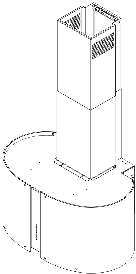
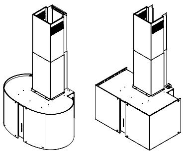
Technical line drawing of a cylindrical industrial or electrical enclosure with a central tower and mounting base (no text or symbols)
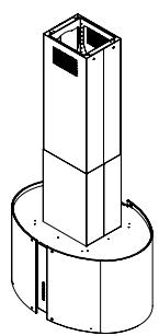
Mirabilia ROUND Wall 67
24 kg
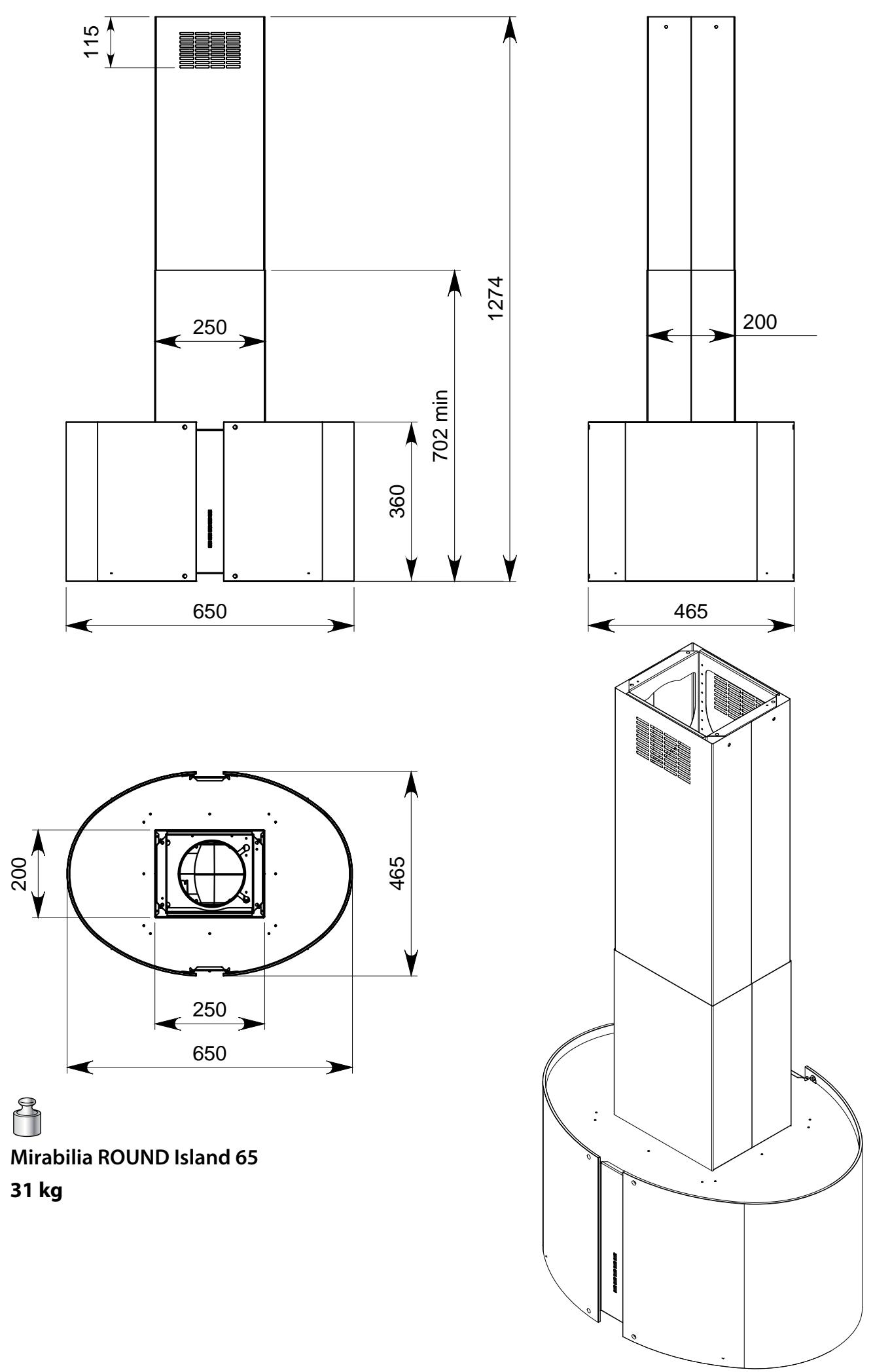
31 kg
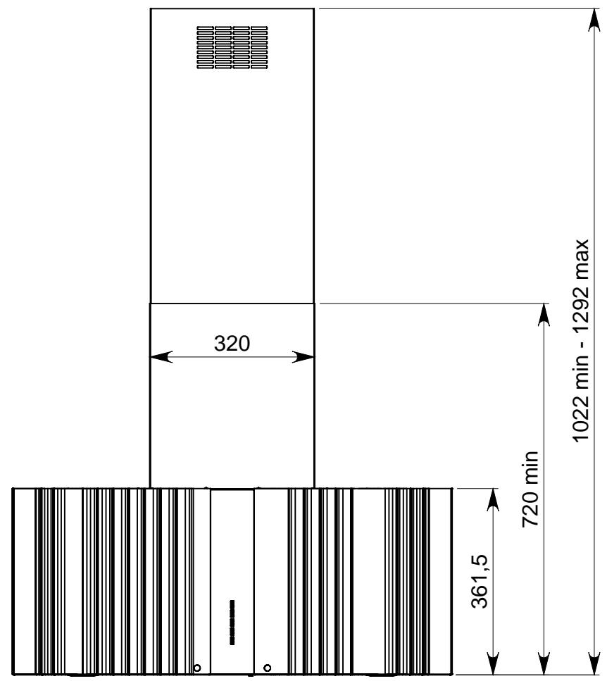
other
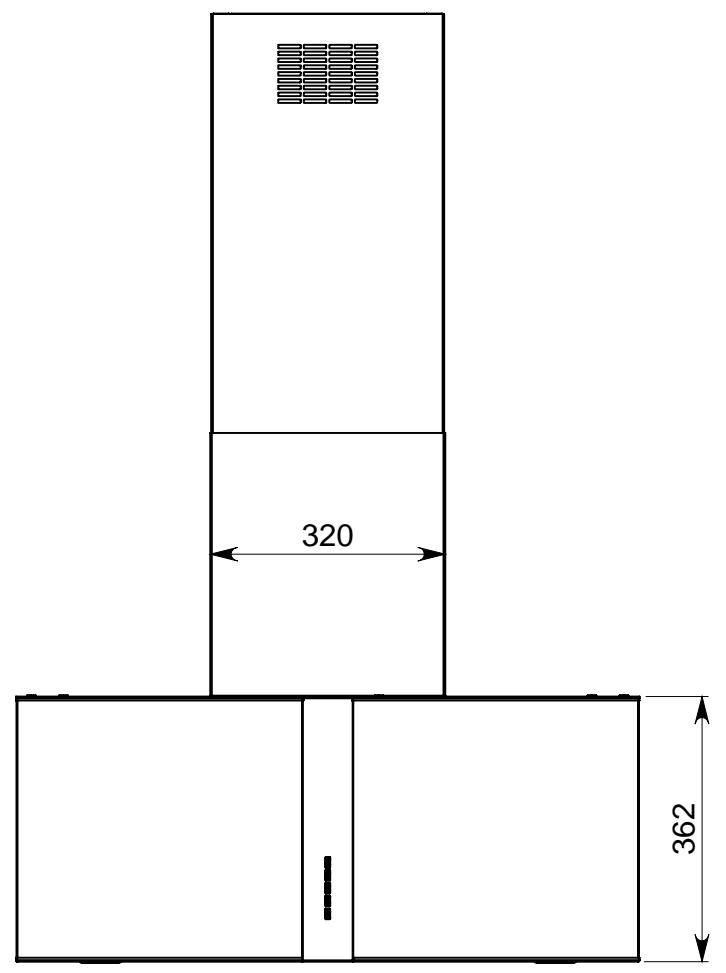
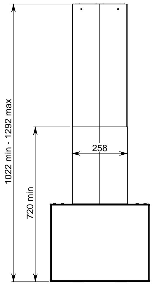
| Dimension | Value | | ----------------- | --------- | | Height (320) | 320 | | Width (720 min) | 720 min | | Height (361.5) | 361.5 | | Height (1022 min - 1292 max) | 1022 min - 1292 max |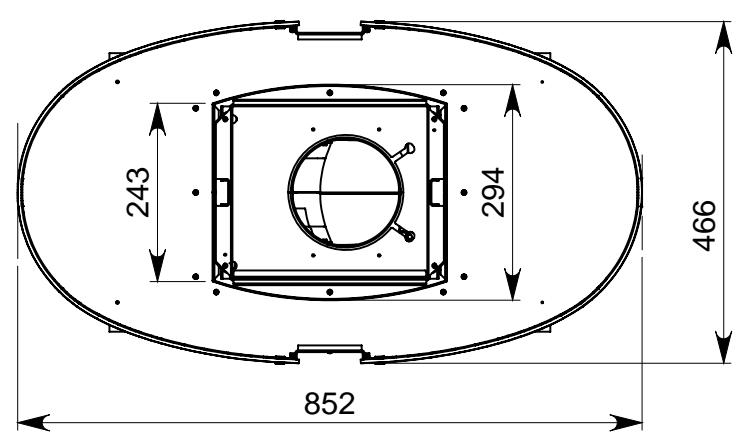

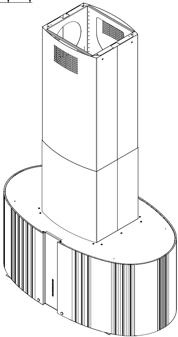
Mirabilia ROUND Island 85
41 kg
natural_image
Technical line drawing of a cylindrical industrial or scientific device with internal components and mounting base (no text or symbols)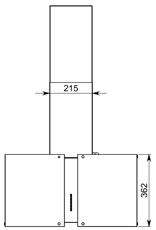

natural_image
Isometric line drawing of a multi-tiered industrial or electrical enclosure structure (no text or symbols)
Mirabilia SQUARE Wall 67
24 kg
natural_image
Isometric technical drawing of a building facade with a vertical column and support structure (no text or symbols)
Mirabilia SQUARE Wall 97
33 kg
other
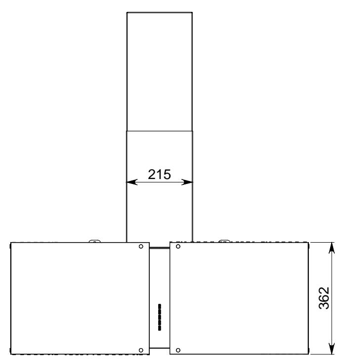
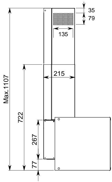
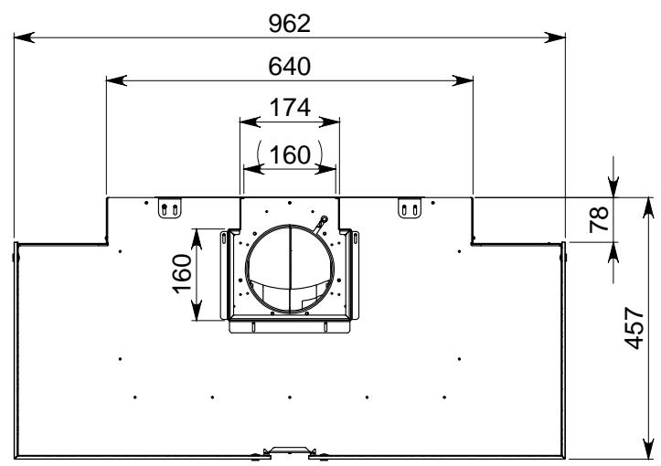
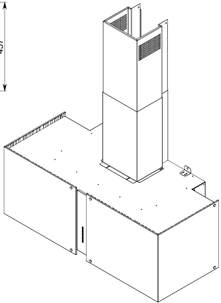
| Dimension | Value | | ----------------- | ----- | | Top Section | 1022 min - 1292 max | | Bottom Section | 720 min | | Width (Bottom) | 258 |
natural_image
Isometric line drawing of a tall industrial chimney mounted on a base (no text or symbols)
Mirabilia SQUARE Island 85
44 kg
natural_image
Technical line drawings of two mechanical or architectural components with no visible text or symbolsMIRABILIA WALL
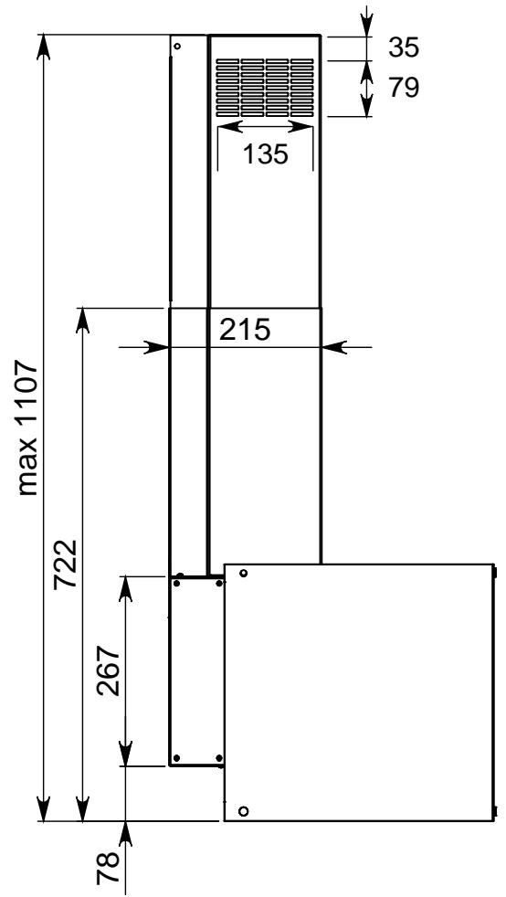
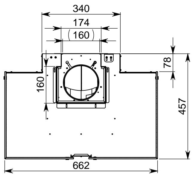
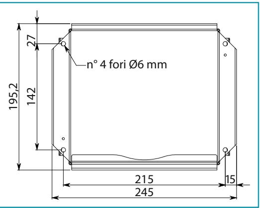
EN - Measurements for installation (1).
| Gas (min.) | Induction (min.) |
| 600 mm | 520 mm |
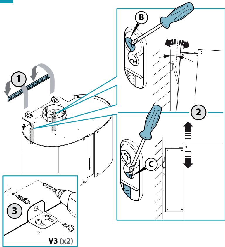
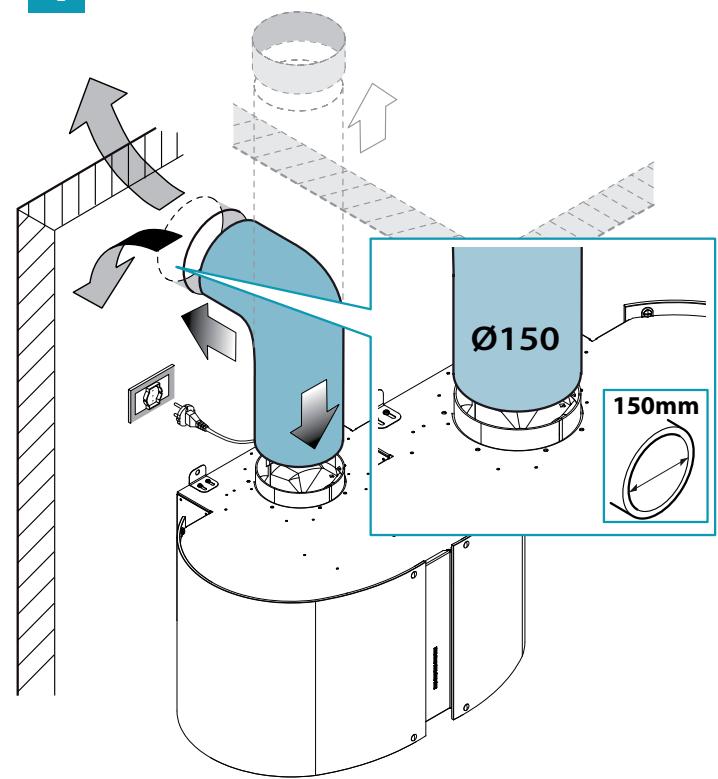
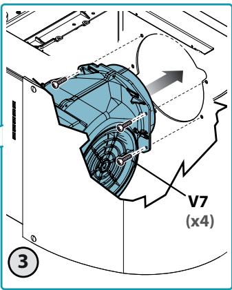
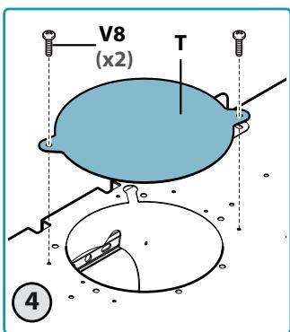
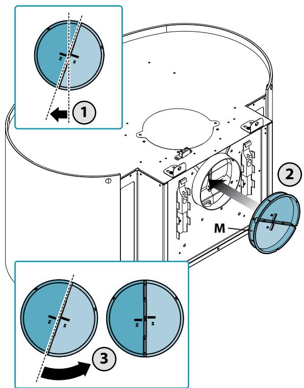
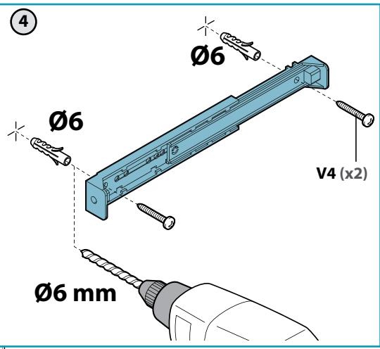
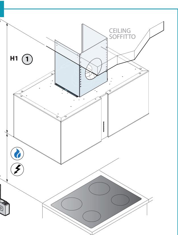
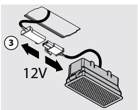
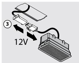
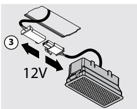
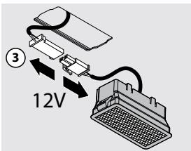
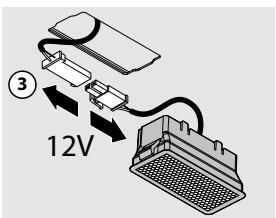
IT - Fissaggio cappa (2), installazione valvola di non ritorno(3) e montaggio tubo d'aspirazione (4).
EN - Hood fastening (2), check valve installation (3) and suction pipe assembly (4).
DE - Befestigung der Abzugshaube (2), Installation des Rückschlagventils (3) und Montage der Ansaugleitung (4).
FR - Fixation de la hotte (2), installation du clapet anti-retour (3) et montage du tuyau d'aspiration (4).
ES - Fijación de la campana (2), instalación de la válvula antirretorno (3) y montaje del tubo de aspiración (4).
RU - Крепление вытяжки (2), установка обратного кла-пана (3) и монтаж всасывающей трубы (4).
PL - Mocowanie okapu (2), montaż zaworu zwrotnego (3) imontaż rury ssącej (4).
NL - Kapbevestiging (2), montage terugslagklep (3) enzuigleiding. (4)
PT - Fixação do exaustor (2), instalação da válvula de não retorno (3) e montagem do tubo de aspiração (4).
DK - Fastgørelse af emhætten (2), montage af kontraventil (3) og rør til udsuget (4).
SE - Fästning av kåpan (2), installation av backventilen (3) samt montering av utsugningsröret (4).
FI - Liesituulettimen kiinnitys (2), vastaventtiilin asennus (3) ja imuputken liitäntä (4).
NO - Feste av ventilatorhette (2), installasjon av tilbakeslagsventil (3) og montasje av innsugingsrør (4).
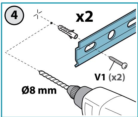
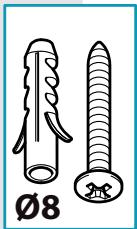
2

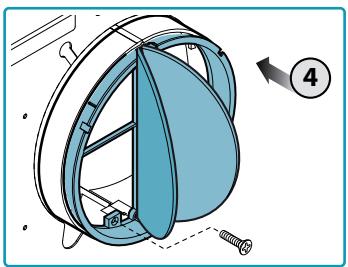
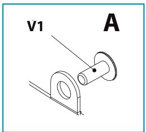
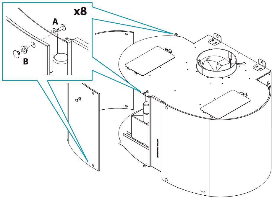
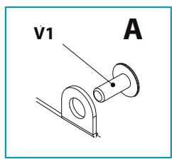
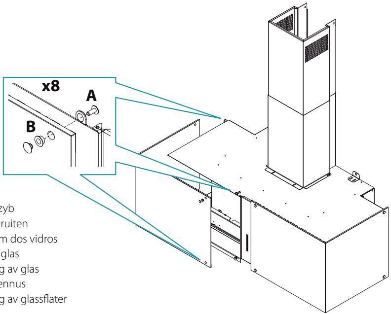
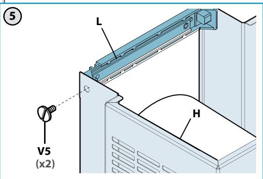
IT - Viti di sicurezza obbligatorie
EN - Mandatory safety screws
DE - Sicherheitsschrauben, obligatorisch
FR - Vis de sécurité obligatoires
ES - Tornillos de seguridad obligatorios
RU - Обязательные предохранительные
винты
PL - Obowiązkowe śruby zabezpieczają-
ce
NL - Verplichte veiligheidsschroeven
PT - Parafusos de segurança obrigatórios
DK - Obligatoriske sikkerhedsskruer
SE - Obligatoriska säkerhetsskruvar
FI - Pakolliset varmistusruuvit
NO - Påkrevde sikkerhetsskruer
3
4
EN - Installation with rear outlet
Connettore comandi
Panel control connector
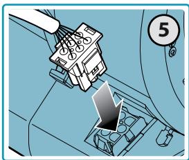
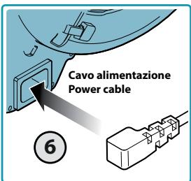
7
natural_image
Diagram of a mechanical device with a blue component and screw base, no visible text or symbols8

IT - Viti di sicurezza obbligatorie
EN - Mandatory safety screws
DE - Sicherheitsschrauben, obligatorisch
FR - Vis de sécurité obligatoires
ES - Tornillos de seguridad obligatorios
RU - Обязательные предохранительные
винты
PL - Obowiązkowe śruby zabezpieczające
NL - Verplichte veiligheidsschroeven
PT - Parafusos de segurança obrigatórios
DK - Obligatoriske sikkerhedsskruer
SE - Obligatoriska säkerhetsskruvar
FI - Pakolliset varmistusruuvit
NO - Påkrevde sikkerhetsskruer
9a
MIRABILIA ROUND
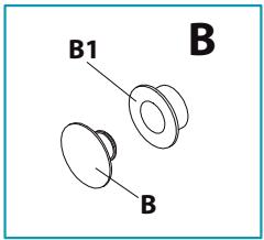
IT - Montaggio vetri
EN - Glass assembly
DE - Montage der Glasplatten
FR - Montage des vitres
ES - Montaje de los cristales
RU - Монтаж стекол
PL - Montaż szyb
NL - Montage ruiten
PT - Montagem dos vidros
DK - Montage glas
SE - Montering av glas
FI - Lasien asennus
NO - Montering av glassflater
IT - Montaggio vetri
EN - Glass assembly
DE - Montage der Glasplatten
FR - Montage des vitres
ES - Montaje de los cristales
RU - Монтаж стекол
PL - Montaż szyb
NL - Montage ruiten
PT - Montagem dos vidros
DK - Montage glas
SE - Montering av glas
FI - Lasien asennus
NO - Montering av glassflater
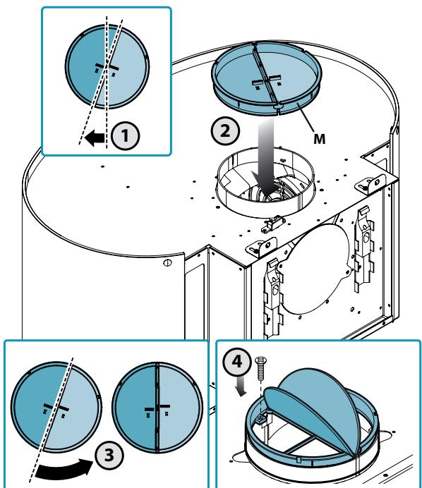
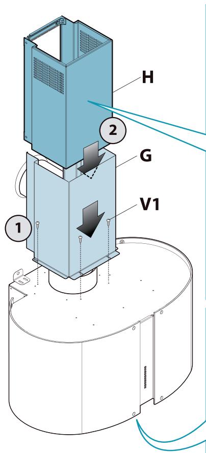
IT - Montaggio camino.
EN - Flue assembly.
DE - Montage des Kamins.
FR - Montage de la cheminée.
ES - Montaje de la chimenea.
RU - Монтаж дымохода.
PL - Montaż komina.
NL - Montage schacht.
PT - Montagem da chaminé.
DK - Montage af skorsten.
SE - Montering av rökgång.
FI - Poistoputken liitäntä.
NO - Montasje av skorstein.
10
natural_image
Isometric illustration of a multi-tiered storage unit with a circular arrow symbol above it (no text or labels)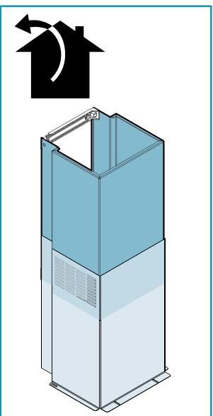
natural_image
Isometric diagram of a tall industrial cabinet with a curved arrow indicating rotation (no text or symbols)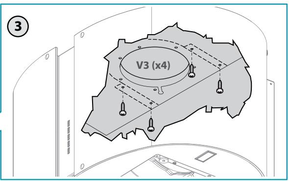
natural_image
Illustration of a hand using a pen to cut a metal bracket (no text or symbols present)

natural_image
Diagram of a mechanical device with two vertical rods and circular components, no text or symbols present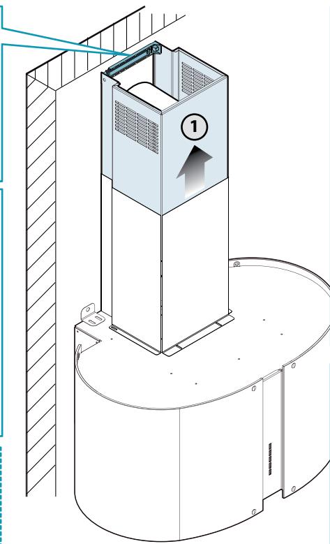
natural_image
Technical line drawing of a mechanical component with a cylindrical base and rectangular top (no text or symbols)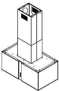
natural_image
Isometric line drawing of a mechanical or architectural component with a vertical column and base (no text or symbols)MIRABILIA ISLAND
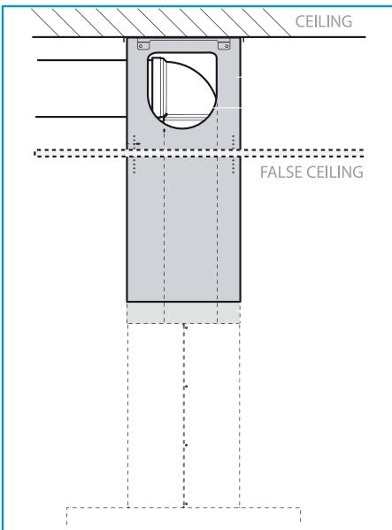
Uscita laterale utilizzabile solo con controsoffitto.
Side outlet which can only be used with false ceiling.
Seitlicher Abzug nur mit Zwischendecke verwendbar.
Sortie latérale utilisable uniquement avec faux-plafond.
Salida lateral utilizable solo con falso techo.
Боковой выход, используемый лишь при наличии подвесного потолка.
Wylot boczny, wykorzystywany tylko na sufitach podwieszanych.
Zijdelingse uitgang enkel bruikbaar met vals plafond.
Saída lateral utilizável apenas com revestimento do teto.
Udgang på siden kun til anvendelse med nedhængt loft.
Sidoutgång endast användbar med undertak.
Sivussa oleva poistoaukko käytettävissä vain sisäkaton kanssa.
Sideutgang som kun kan brukes med undertak.
IT - Operazioni preliminari: separare traliccio superiore da traliccio inferiore (1).
EN - Preliminary operations: separate upper trellis from lower trellis (1).
DE - Vorbereitende Vorgänge: die obere Strebe von der unteren Strebe trennen (1).
FR - Opérations préliminaires: séparer le rail supérieur du rail inférieur (1).
ES - Operaciones preliminares: separar la estructura superior de la estructura inferior (1).
RU - Предварительные операции: отдели-
те верхнюю конструкцию от нижней
(1).
PL - Operacje wstępne: oddzielić górny słup d słupa dolnego (1).
NL - Voorbereidingen: scheid het bovenste raamwerk van het onderste raamwerk (1).
PT - Operações preliminares: separar a treliça superior da treliça inferior (1).
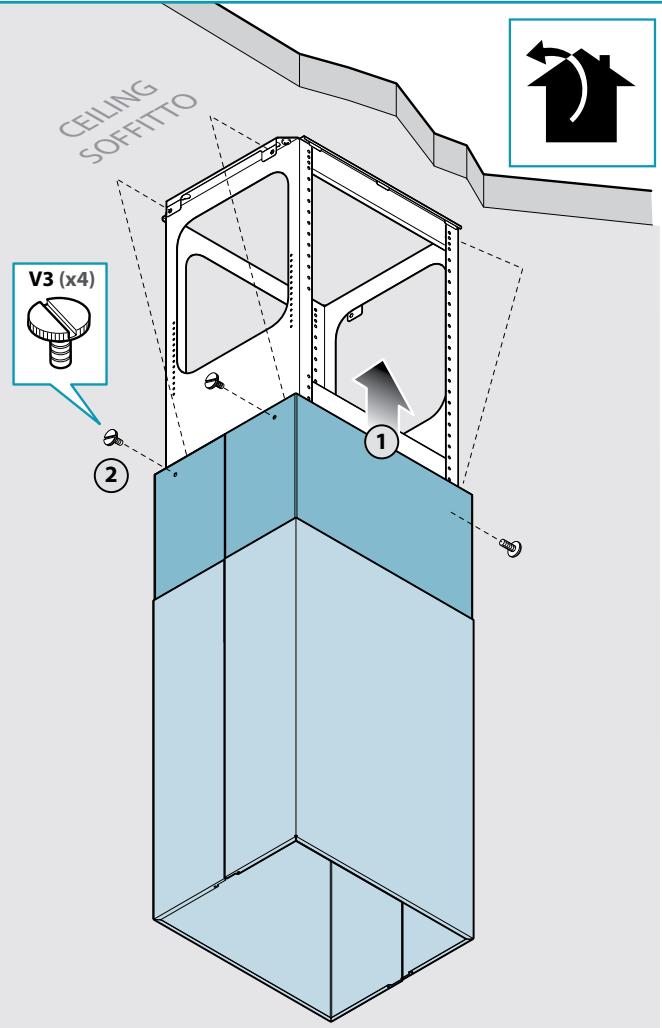
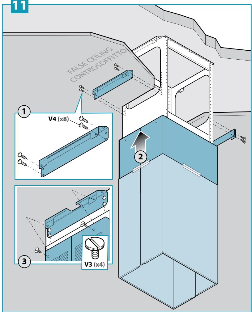
IT - Installazione a soitto (2), installazione a controsoitto(3) e installazione a soitto senza prolunga camino e traliccio superiore (4).
EN- Ceiling installation (2), false ceiling installation (3) and ceiling installation without chimney extension and upper trestle (4).
DE - Deckeninstallation (2), Zwischendeckeninstallation (3) und Deckeninstallation ohne Abluftkaminverlängerung und obere Strebe (4).
FR - Installation au plafond (2), installation sur faux-plafond (3) et installation au plafond sans extension de cheminée et sans rail de ixation supérieure (4).
ES - Instalación en el techo (2), instalación en el contratecho (3) e instalación en el techo sin extensión de chimenea y poste superior (4).
RU - Монтаж на потолок (2), монтаж на подвесной потолок (3) и монтаж на потолок без удлинителя дымохода и верхнего каркаса (4).
PL - Instalacja na suicie (2), instalacja na suicie podwieszanym (3) i instalacja na suicie bez przedłużenia komina i kratki górnej (4).
NL - Installatie aan het plafond (2), installatie aan het verlaagd plafond (3) en installatie aan het plafond zonder verlenging schoorsteen en bovenste raamwerk (4).
PT - Instalação no teto (2), instalação em teto falso (3) e instalação no teto sem extensão chaminé e treliça superior (4).
DK - Installation i loftet (2), installation i nedsænket loft (3) og installation i loft uden kaminforlængelse og øvre stålskelet (4).
SE - Takmontering (2), undertaksmontering (3) och takmontering utan förlängning av käpa och övre galler (4).
FI - Kattoasennus (2), välikattoasennus (3) ja kattoasennus ilman hormijatketta ja yläsäleikköä (4).
NO- Installasjon i tak (2), installasjon i undertak (3) og installasjon i tak uten pipeforlengelse og øvre listverk (4).
2
3
4
| Gas (min.) | Induction (min.) |
| 600 mm | 520 mm |
EN - Trestle (5) and extension (6) assembly.
6
IT - Installazione a soffitto senza traliccio superiore e senza prolunga (7).
EN - Ceiling mount without upper trestle and without extension (7).
DE - Installation an Decke ohne oberen Gittermast und ohne Verlängerung (7).
FR - Installation sur plafond sans support de fixation supérieur et sans rallonge (7).
ES - Instalación en techo sin estructura superior y sin prolongación (7).
RU - Установка на потолок без верхнего каркаса и без удлинителя (7).
PL - Instalacja na suficie bez kratki górnej i przedłużenia (7).
NL - Installatie aan het plafond zonder bovenste raamwerk en extensie (7).
PT - Instalação no teto sem treliça superior e sem extensão (7).
DK - Loftinstallation uden øvre tværbjælke og uden forlængerstykke (7).
SE - Installation i tak utan övre fackverk och utan förlängning (7).
FI - Kattoasennus ilman yläsäleikköä ja jatketta (7).
NO- Installasjon i tak uten øvre listverk og uten forlengelse (7).
7
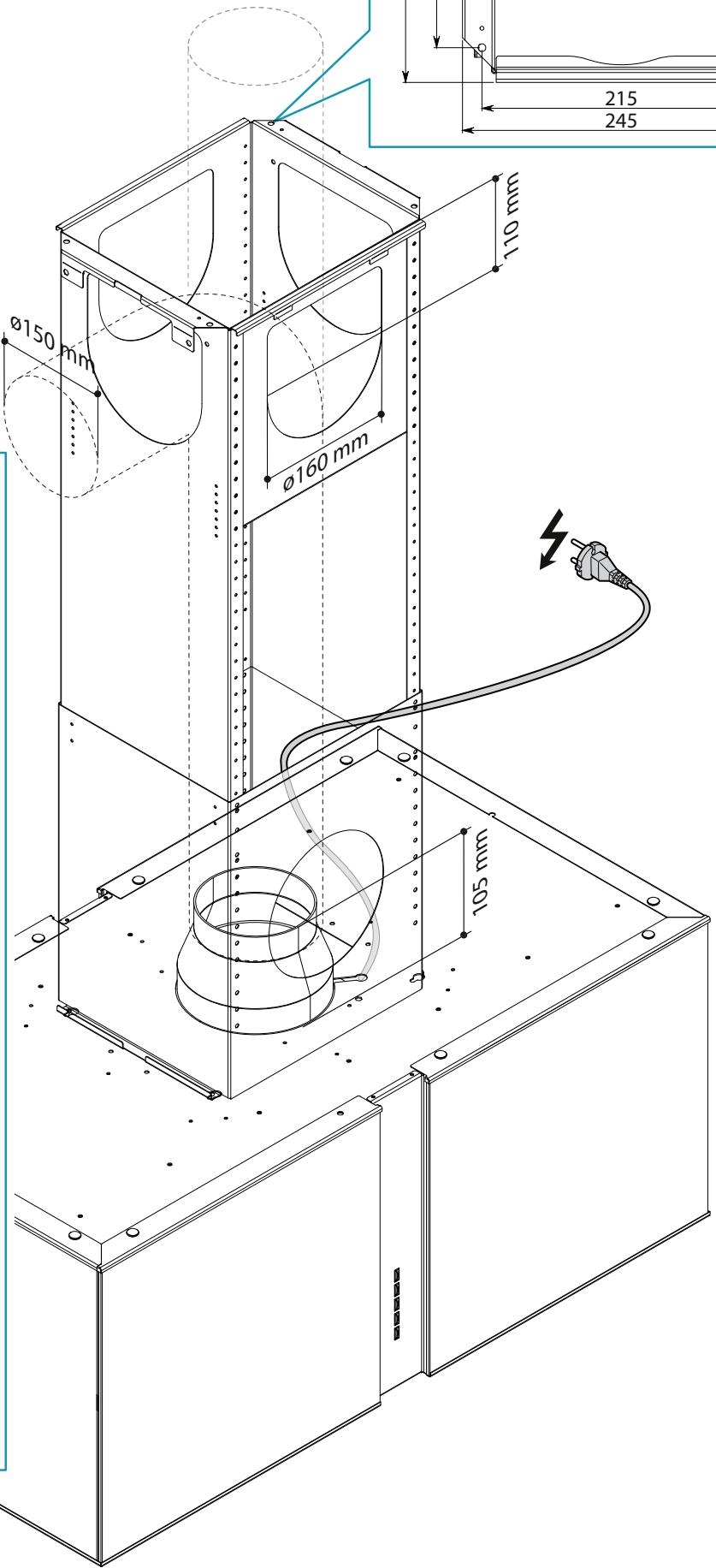
IT - Montaggio valvola di non ritorno (7); tubo aspirazione (8); assemblaggio camino (9).
EN - Check valve assembly (7); exhaust pipe (8); chimney assembly (9).
DE - Montage Rückschlagventil (7); Ansaugrohr (8); Kamingruppe (9).
FR - Montage clapet anti-retour (7) ; tube d'aspiration (8) ; assemblage conduit d'évacuation (9).
ES - Montaje de válvula de no retorno (7); tubo de aspiración (8); montaje de chimenea (9).
RU - Монтаж обратного клапана (7); всасывающей трубы (8); сборка дымохода (9).
PL - Montaż zaworu zwrotnego (7), rury zasysającej (8); montaż komina (9).
NL - Montage terugslagklep (7); inlaatleiding (8); assemblage schoorsteen (9).
PT - Montagem da válvula de não retorno (7); tubo aspiração (8); montagem chaminé (9).
DK-Montering af kontraventil (7); udsugningsrør (8); montering af skorsten (9).
SE - Montering av backventil (7); sugledning (8); sammansättning av skorsten (9).
FI - Vastaventtiilin (7), imuputken (8) asennus.
NO- Montering av stengeventil (7), oppsugingsrør (8), montering av pipe (9).
7
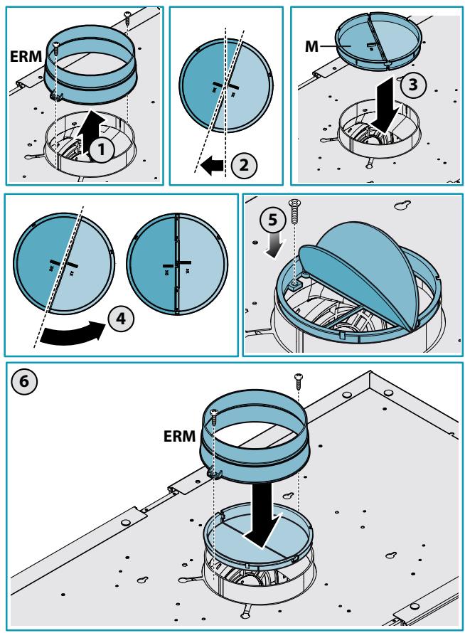
8

9
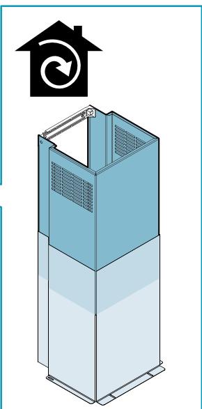
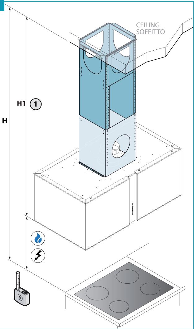
IT - Configurazione a soffitto (10);
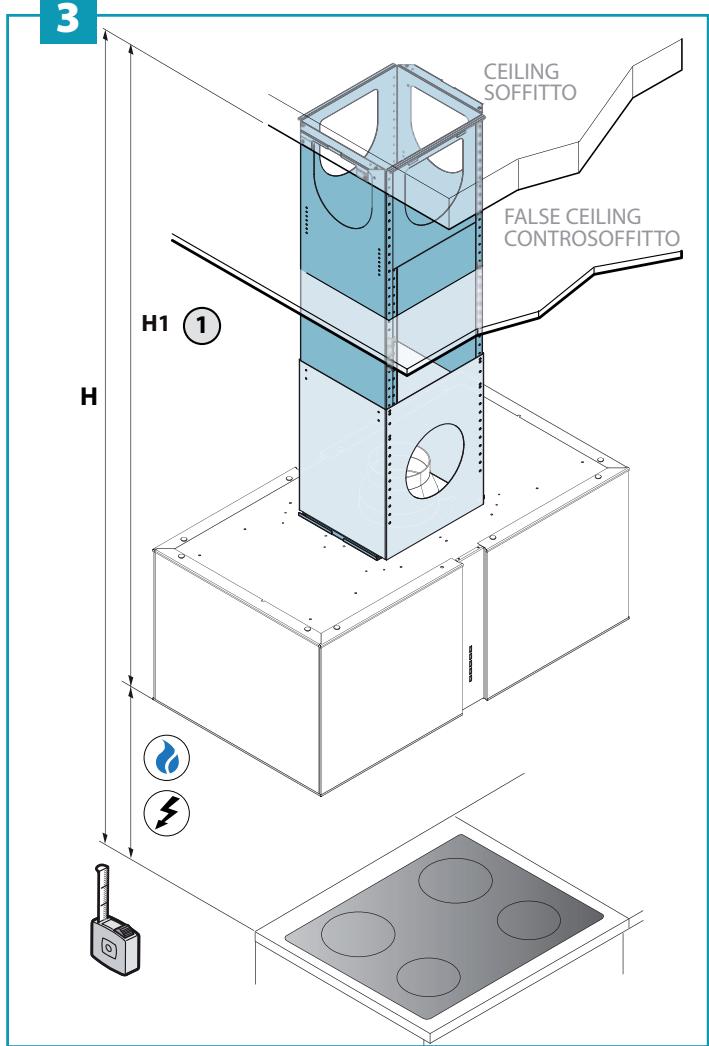
Configurazione a controsoffitto (11)(12).
EN - Ceiling configuration (10); False ceiling configuration (11)(12).
DE - Konfigurierung Decke (10);
Konfigurierung abgehängte Decke (11)(12).
FR - Installation sur plafond (10); Installation sur faux-plafond (11)(12).
ES - Configuración en techo (10);
Configuración en falso techo (11)(12).
RU - Конфигурация на потолке (10);
Конфигурация на подвесном потолке (11)(12).
PL - Konfiguracja na suficie (10);
Konfiguracja na suficie podwieszanym (11)(12).
NL - Configuratie aan plafond (10);
Configuratie aan verlaagd plafond (11)(12).
PT - Configuração no teto (10);
Configuração em teto falso (11)(12).
DK - Loftskonfiguration (10);
Konfiguration med nedsænket loft (11)(12).
SE - Utförande för innertak (10); Utförande för undertak (11)(12).
FI - Asetus kattoon (10); Asetus välikattoon (11)(12).
NO - Konfigurasjon i tak (10);
Konfigurasjon i undertak (11)(12).
10
11
12
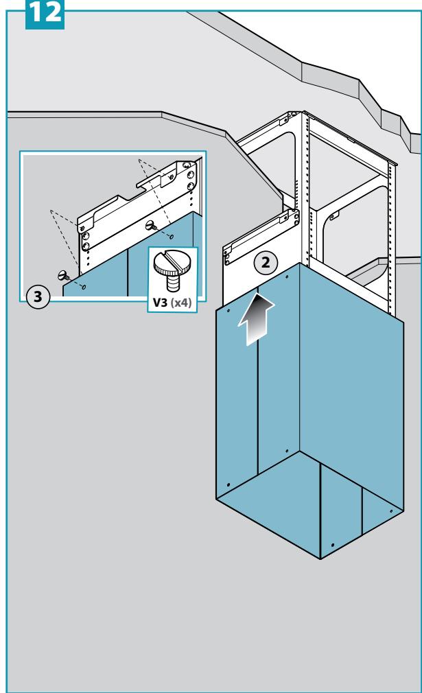
EN - Motor chamber installation (13); electrical connection and chimney + extension installation (14).
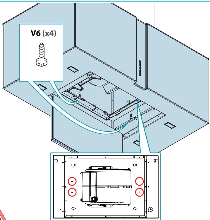

EN - Mandatory safety screws
natural_image
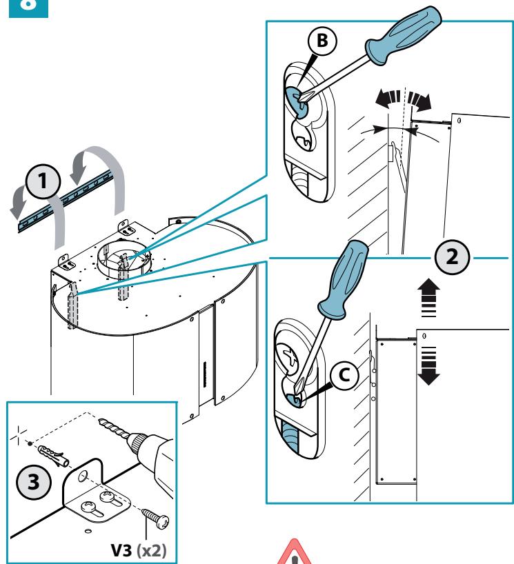
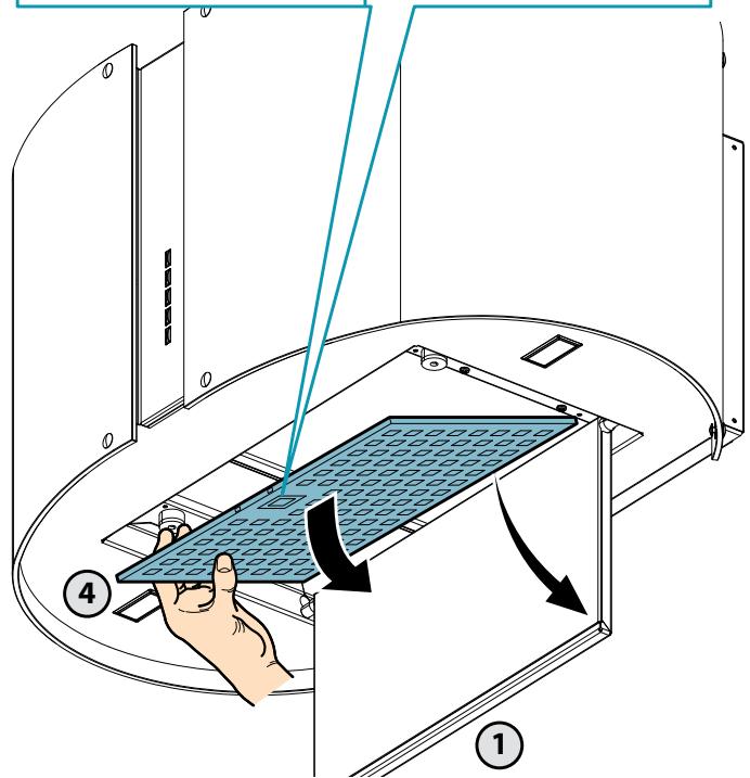
Four technical line drawings of structural components with no visible text or symbolsEN - Assembly of factory-itted filter (1)+(2).
natural_image
Illustration of a computer monitor with directional arrows and triangular shapes, no text or symbols present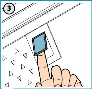
2
natural_image
Technical illustration of a mechanical device with exploded view and close-up details (no text or symbols)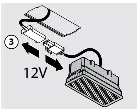
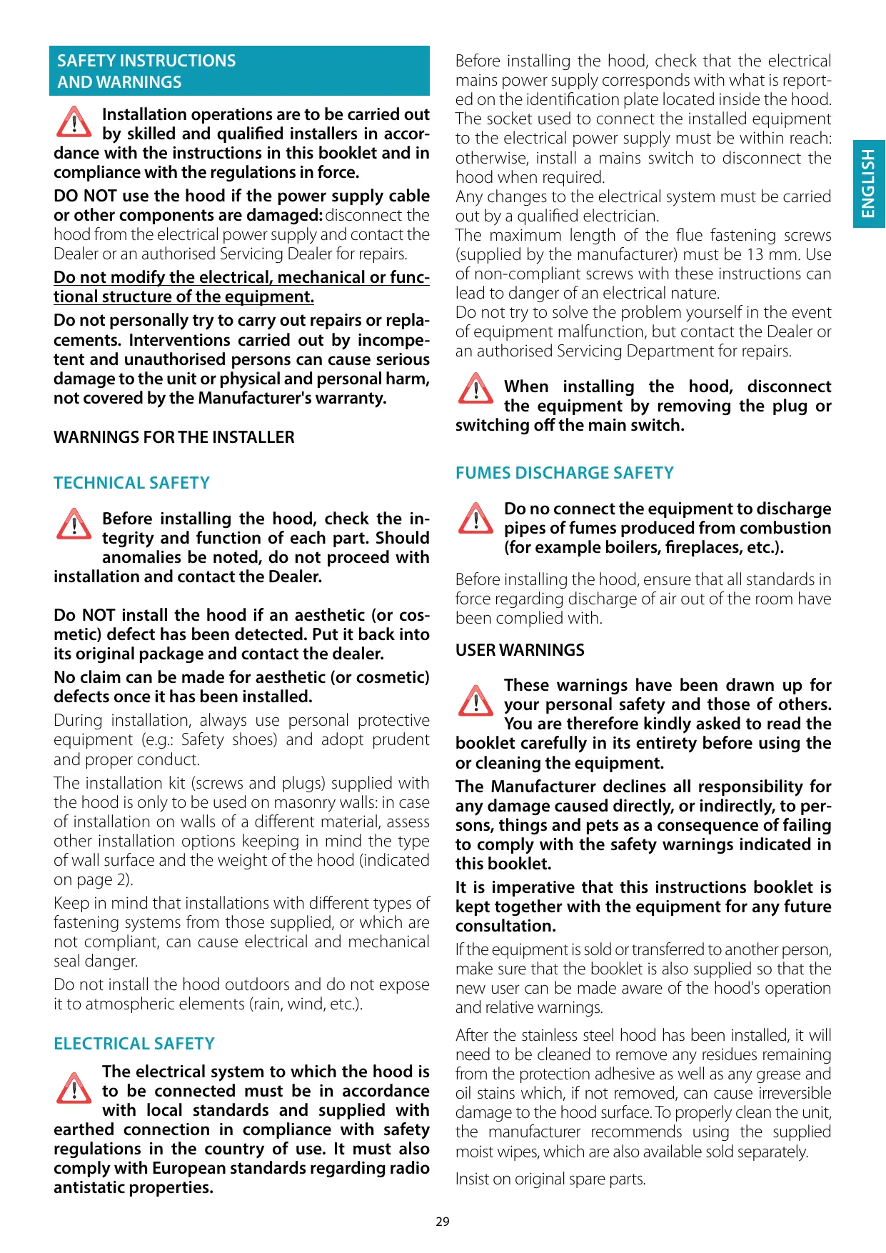
SAFETY INSTRUCTIONS AND WARNINGS
Installation operations are to be carried out by skilled and qualified installers in accordance with the instructions in this booklet and in compliance with the regulations in force.
DO NOT use the hood if the power supply cable or other components are damaged: disconnect the hood from the electrical power supply and contact the Dealer or an authorised Servicing Dealer for repairs.
Do not modify the electrical, mechanical or functional structure of the equipment.
Do not personally try to carry out repairs or replacements. Interventions carried out by incompetent and unauthorised persons can cause serious damage to the unit or physical and personal harm, not covered by the Manufacturer's warranty.
WARNINGS FOR THE INSTALLER
TECHNICAL SAFETY
Before installing the hood, check the integrity and function of each part. Should anomalies be noted, do not proceed with installation and contact the Dealer.
Do NOT install the hood if an aesthetic (or cosmetic) defect has been detected. Put it back into its original package and contact the dealer.
No claim can be made for aesthetic (or cosmetic) defects once it has been installed.
During installation, always use personal protective equipment (e.g.: Safety shoes) and adopt prudent and proper conduct.
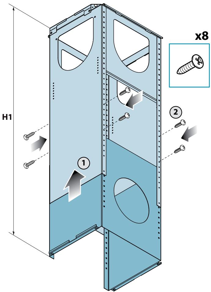
The installation kit (screws and plugs) supplied with the hood is only to be used on masonry walls: in case of installation on walls of a different material, assess other installation options keeping in mind the type of wall surface and the weight of the hood (indicated on page 2).
Keep in mind that installations with different types of fastening systems from those supplied, or which are not compliant, can cause electrical and mechanical seal danger.
Do not install the hood outdoors and do not expose it to atmospheric elements (rain, wind, etc.).
ELECTRICAL SAFETY
The electrical system to which the hood is to be connected must be in accordance with local standards and supplied with earthed connection in compliance with safety regulations in the country of use. It must also comply with European standards regarding radio antistatic properties.
Before installing the hood, check that the electrical mains power supply corresponds with what is reported on the identification plate located inside the hood. The socket used to connect the installed equipment to the electrical power supply must be within reach: otherwise, install a mains switch to disconnect the hood when required.
Any changes to the electrical system must be carried out by a qualified electrician.
The maximum length of the flue fastening screws (supplied by the manufacturer) must be 13 mm. Use of non-compliant screws with these instructions can lead to danger of an electrical nature.
Do not try to solve the problem yourself in the event of equipment malfunction, but contact the Dealer or an authorised Servicing Department for repairs.
When installing the hood, disconnect the equipment by removing the plug or switching off the main switch.
FUMES DISCHARGE SAFETY
Do no connect the equipment to discharge pipes of fumes produced from combustion (for example boilers, fireplaces, etc.).
Before installing the hood, ensure that all standards in force regarding discharge of air out of the room have been complied with.
USER WARNINGS
These warnings have been drawn up for your personal safety and those of others. You are therefore kindly asked to read the booklet carefully in its entirety before using the or cleaning the equipment.
The Manufacturer declines all responsibility for any damage caused directly, or indirectly, to persons, things and pets as a consequence of failing to comply with the safety warnings indicated in this booklet.
It is imperative that this instructions booklet is kept together with the equipment for any future consultation.
If the equipment is sold or transferred to another person, make sure that the booklet is also supplied so that the new user can be made aware of the hood's operation and relative warnings.
After the stainless steel hood has been installed, it will need to be cleaned to remove any residues remaining from the protection adhesive as well as any grease and oil stains which, if not removed, can cause irreversible damage to the hood surface. To properly clean the unit, the manufacturer recommends using the supplied moist wipes, which are also available sold separately.
Insist on original spare parts.
INTENDED USE
The equipment is solely intended to be used to extract fumes generated from cooking food in non-professional domestic kitchens: any other use is improper. Improper use can cause damage to persons, things, pets and exempts the Manufacturer from any liability.
The equipment can be used by children over the age of 8 and by persons with reduced physical, sensory and mental abilities, or with no experience or knowledge, as long as they do so under supervision or after having received relative instructions regarding safe use of the equipment and understanding of the dangers connected to it.
Children are not to play with the equipment. Cleaning and maintenance by the user must not be carried out by children without supervision.
USE AND CLEANING WARNINGS

Before cleaning or carrying out maintenance operations, disconnect the equipment by removing the plug or switching the main switch.
Do not use the hood with wet hands or bare feet.
Always check that all electrical parts (lights, extractor fan) are off when the equipment is not being used.
The maximum overall weight of any objects placed or hung (if applicable) on the hood must not exceed 1.5 Kg.
Always supervise the cooking process during the use of deep-fryers: Overheated oil can catch fire.
Do not leave open, unattended flames under the hood.
Do not prepare food over an open flame under the hood.
Never use the hood without the metal anti-grease filters: in this case, grease and dirt will deposit in the equipment and compromise its operation.
Accessible parts of the hood can be hot when used at the same time as the cooking appliances.
Do not carry out any cleaning operations when parts of the hood are still hot.
There can be a risk of fire if cleaning is not carried out according to the instructions and products indicated in this booklet.
Disconnect the main switch when the equipment is not used for long periods of time.

If other appliances that use gas or other fuels are being used at the same time (boiler, stove, fireplaces, etc.), make sure the room
where the fumes are discharged is well-ventilated, in compliance with the local regulations.
INSTALLATION
only intended for qualified personnel

Before installing the hood, carefully read the chapter 'SAFETY INSTRUCTIONS AND WARNINGS'.
TECHNICAL FEATURES
The technical specifications are exhibited on the labels located inside the hood.
POSITIONING
The minimum distance between the highest part of the cooking equipment and the lowest part of the hood is indicated in the installation instructions.
Generally, when the hood is placed over gas cookers, the distance must be at least 65 cm (25.6"). However, according to an interpretation of standard EN60335-2-31 dated 11-07-2002 of TC61 (sub-clause 7.12.1 meeting 15 agenda item 10.11), the minimum distance between the cooker and lower part of the hood can be reduced to the quota reported in the installation instructions.
Should the instructions for the gas cooker specify a greater distance, this must be taken into consideration.
Do not install the hood outdoors and do not expose it to outdoor environment (rain, wind, etc.).
ELECTRICAL CONNECTION
(only intended for qualified personnel)

Disconnect the equipment from electrical mains power supply before carrying out any operations on the hood.
Ensure that the wires inside the hood are not disconnected or cut:
in the event of damage, contact your nearest Servicing Department.
Refer to qualified personnel for electrical connections.
Connection must be carried out in compliance with the provisions of law in force.
Before connecting the hood to the electrical mains power supply, check that:
- voltage supply corresponds with what is reported on the data plate located inside the hood;
- the electrical system is compliant and can withstand the load (see the technical specifications located inside the hood);
- the power supply plug and cable do not come into contact with temperatures exceeding 70 °C;
- the power supply system is effectively and properly connected to earth in compliance with regulations in force;
• the socket used to connect the hood is within reach.
In case of:
- devices fitted with cables without a plug: the type of plug to use is a "standardised" one. The wires must be connected as follows: yellow-green for earthing, blue for neutral and brown for the phase. The plug must be connected to an adequate safety socket.
- fixed equipment not provided with a power supply cable and plug, or any other device that ensures disconnection from the electrical mains, with an opening gap of the contacts that enables total disconnection in overvoltage category III conditions.
Said disconnection devices must be provided in the mains power supply in compliance with installation regulations.
The yellow/green earth cable must not be cut off by the switch.
The Manufacturer declines all responsibility for failure to comply with the safety regulations.
EXTERNAL EXHAUST HOOD (SUCTION)
In this version the fumes and vapours are discharged outside through the exhaust pipe.
To this end, the hood outlet fitting must be connected via a pipe, to an external output.
The outlet pipe must have:
- a diameter not less than that of the hood fitting.
- a slight slope downwards (drop) in the horizontal sections to prevent condensation from flowing back into the motor.
• the minimum required number of bends. - the minimum required length to avoid vibrations and reduce the suction performance of the hood.
You are required to insulate the pipes if it passes through cold environments. In the presence of motors with 800m3/h or higher, a check valve is present to prevent external air flowing back.
Deviation for Germany:
when the kitchen hood is used at the same time as appliances that are powered by energy other than electricity, the negative pressure in the room must not exceed 4 Pa (4 x 10⁻⁵ bar).
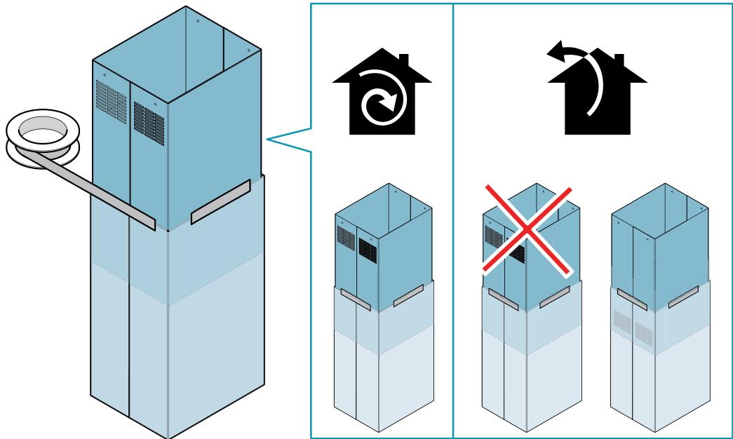
HOOD WITH INTERNAL RECIRCULATION (FILTERING)

In this model, the air passes through the charcoal filters to be purified and recycled in the environment.
Ensure that the active carbon filters are assembled into the hood, if not, install them as indicated in the assembly instructions.

In this version the check valve must not be assembled: remove it if it is on the air outlet fitting of the motor.
ASSEMBLY INSTRUCTIONS
only intended for qualified personnel

The hood can be installed in various configurations.
The generic assembly steps apply to all installations; for each case, follow the specific steps provided for the required installation.
OPERATION
WHEN TO TURN ON THE HOOD?
Switch on the hood at least one minute before starting to cook to direct fumes and vapours towards the suction surface.
After cooking, leave the hood operating until complete extraction of all vapours and odours. By means of the Timer function, it is possible to set auto switch-off function which will allow the hood to turn off automatically after 15 minutes of operation.
WHICH SPEED IS TO BE SELECTED?
1st speed: maintains the circulation of clean air with low electricity consumption.
2nd speed: normal conditions of use.
3rd speed: presence of strong odours and vapours.
4th speed: rapid disposal of odours and vapours.
WHEN SHOULD THE FILTERS BE WASHED OR REPLACED?
The metal filters must be cleaned every 30 hours of operation.
The active carbon filters must be replaced every 3-4 months, depending on the use of the hood.
For further details see the "MAINTENANCE" chap.
ELECTRONIC PUSHBUTTON PANEL
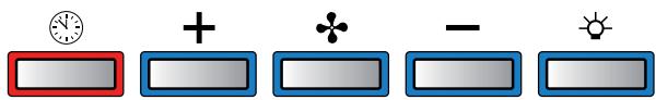
| Motor ON/OFFUpon start-up, the speed is that stored at the previous operation. | ||
| Increase speed from 1 to 4Speed 4 is only active for a few minutes, then speed 3 activates. | The speeds are indicated by the LEDs on the keys: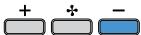 Speed 1 Speed 1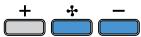 Speed 2 Speed 2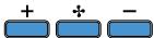 Speed 3 Speed 3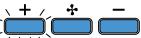 Speed 4("+" LED flashing) Speed 4("+" LED flashing) | |
| Reduce speed from 4 to 1 | ||
| Light on/offPress for 3 seconds for room lightWith motor OFF: Use + and — to adjust intensity | ||
| TIMER(red LED flashing)Auto switch-off after 15 min.The function deactivates (red LED off) if:- The TIMER key (💡) is pressed again.- The ON/OFF key (💡) is pressed. FILTER ALARM(red LED steady on with (💡) off)Anti-grease filter maintenance after approximately 30 hours of operation.Press (💡) the meter for 3 seconds to reset. | ||
MAINTENANCE

Before cleaning or carrying out maintenance operations, disconnect the equipment by removing the plug or switching off the main switch.
Do not use detergents containing abrasive, acidic or corrosive substances or abrasive cloths.
Regular maintenance guarantees proper operation and performance over time. Special attention is to be paid to the metal anti-grease filters: frequent cleaning of the filters and their supports ensures that no flammable grease is accumulated.
CLEANING OF EXTERNAL SURFACES
You are advised to clean the external surfaces of the hood at least once every 15 days to prevent oily substances and grease from sticking to them. To clean the brushed stainless steel hood, the Manufacturer recommends using "Magic Steel" wipes.
Alternatively and for all the other types of surfaces, it can be cleaned using a damp cloth, slightly moistened with mild, liquid detergent or denatured alcohol. Complete cleaning by rinsing well and drying with soft cloths.

Do not use too much moisture or water around the push button control panel and lighting devices in order to prevent humidity from reaching electronic parts.
The glass panels can only be cleaned with specific, non-corrosive or non-abrasive detergents using a soft cloth.
The Manufacturer declines all responsibility for failure to comply with these instructions.
GLASS CLEANING
To remove the glass, see the assembly instructions.
CLEANING OF INTERNAL SURFACES

Do not clean electrical parts, or parts related to the motor inside the hood, with liquids or solvents.
For the internal metal parts, see the previous paragraph.
METAL ANTI-GREASE FILTERS
It is advised to frequently wash the metal filters (at least once a month) leaving them to soak in boiling water and cleaning solution for 1 hour, taking care not to bend them.
Do not use corrosive, acid or alkaline detergents.
Rinse them well and wait for them to be completely dry before reassembling them.
Washing in a dishwasher is permitted, however, it may cause the filter material to darken: to reduce the possibility of this problem from happening, use low-temperature washes (55°C max.).
To extract and insert the metal anti-grease filters see the assembly instructions.
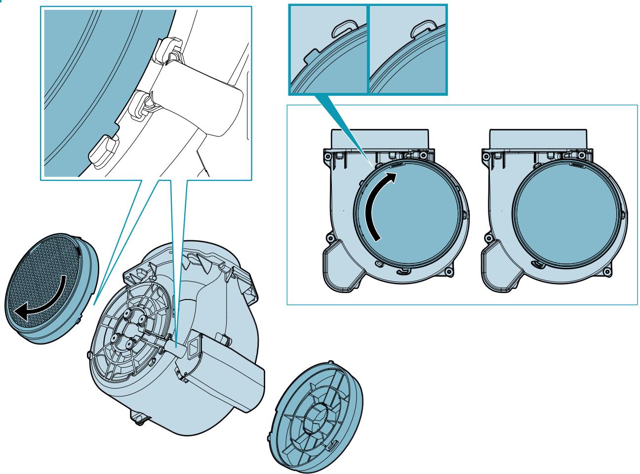
ACTIVE CARBON FILTERS
These filters retain the odours in the air that passes through them. The purified air is recirculated into the environment.
The active carbon filters must be replaced on average every 3-4 months under normal conditions of use.
See assembly instructions to replace the active carbon filters.
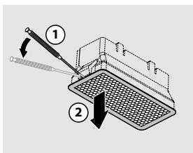
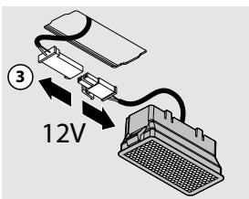
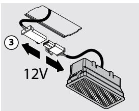
LIGHTING
The range hood is equipped with high efficiency, low consumption LED spotlights with an extremely long life-span under normal use conditions.
Should the LED spotlight need to be replaced, proceed as shown in the figure.
DISPOSAL AFTER END OF USEFUL LIFE

The crossed-out trash or refuse bin symbol on the appliance means that the product is WEEE, i.e. "Waste electrical and electronic equipment", accordingly it must not be disposed of with regular unsor-
ted waste (i.e. with "mixed household waste"), but it must be disposed of separately so that it can undergo specific processing for its re-use, or a specific treatment, to remove and safely dispose of any substances that may be harmful to the environment and remove the raw materials that can be recycled. Proper disposal of these products contributes to saving valuable resources and avoid potential negative effects on personal health and the environment, which may be caused by inappropriate disposal of waste.
You are kindly asked to contact your local authorities for further information regarding the designated waste collection points nearest to you. Penalties for improper disposal of such waste can be applied in compliance with national regulations.
INFORMATION ON DISPOSAL IN EUROPEAN UNION COUNTRIES
The EU WEEE Directive was implemented differently in each country, accordingly, if you wish to dispose of this appliance we suggest contacting your local authorities or dealer to find out what the correct method of disposal is.
INFORMATION ON DISPOSAL IN NON-EUROPEAN UNION COUNTRIES
The crossed-out trash or refuse bin symbol is only valid in the European Union: if you wish to dispose of this appliance in other countries, we suggest contacting your local authorities or dealer to find out what the correct method of disposal is.

WARNING!
The Manufacturer reserves the right to make changes to the equipment at any time and without prior notice. Printing, translation and reproduction, even partial, of this manual are bound by the Manufacturer's authorisation.
Technical information, graphic representations and specifications in this manual are for information purposes and cannot be divulged.
This manual is written in Italian. The Manufacturer is not responsible for any transcription or translation errors.
FILTRES AU CHARBON ACTIF

ÉLIMINATION EN FIN DE VIE
UTYLIZACJA PO ZAKOŃCZENIU OKRESU EKSPLOATACJI

VEILIGHEIDSINSTRUCTIES EN WAARSCHUWINGEN
AFZUIGKAP MET AFVOER NAAR BUITEN

HVILKEN HASTIGHED SKAL MAN VÄLGE?
BORTSKAFFELSE VED ENDT LEVETID


KASSERING I SLUTET AV LIVSLÄNGDEN

HÄVITTÄMINEN KÄYTÖN LOPUTTUA


KASSERING VED ENDT LEVETID
