OF 1400 EQ - Router FESTOOL - Free user manual and instructions
Find the device manual for free OF 1400 EQ FESTOOL in PDF.
| Product type | Router |
| Brand | FESTOOL |
| Model | OF 1400 EQ |
| Power consumption | 1400 W |
| No-load speed | 10000 - 22000 rpm |
| Fast depth adjustment | 70 mm |
| Fine depth adjustment | 8 mm (graduation 0.1 mm) |
| Spindle thread | M22 x 1.0 |
| Max. cutter diameter | 63 mm |
| Weight (without cable) | 4.5 kg |
| Protection class | II (double insulation) |
| Machinable materials | Wood, plastics, aluminum, plaster, cardboard |
| Electronic functions | Soft start, speed regulation, constant speed control, thermal protection |
| Brake (EBQ model) | Electronic quick brake (spindle stop in ~2 s) |
| Available collet diameters | 6, 6.35, 8, 9.53, 10, 12, 12.7 mm |
| Sound level (acoustic pressure) | 82 dB(A) |
| Sound level (sound power) | 93 dB(A) |
| Vibration (emission value) | 3.5 m/s² |
| Extraction connection | 27 or 36 mm |
| Included accessories | Side stop, wrench, clamping collet |
| Warranty | 24 months (EU), 12 months minimum |
Frequently Asked Questions - OF 1400 EQ FESTOOL
User questions about OF 1400 EQ FESTOOL
0 question about this device. Answer the ones you know or ask your own.
Ask a new question about this device
Download the instructions for your Router in PDF format for free! Find your manual OF 1400 EQ - FESTOOL and take your electronic device back in hand. On this page are published all the documents necessary for the use of your device. OF 1400 EQ by FESTOOL.
USER MANUAL OF 1400 EQ FESTOOL
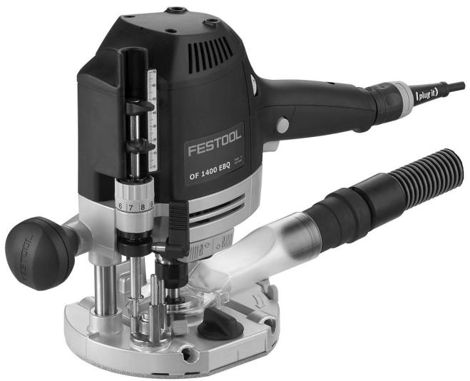
OF 1400 EB OF 1400 EBQ
3a
4
5
8
9
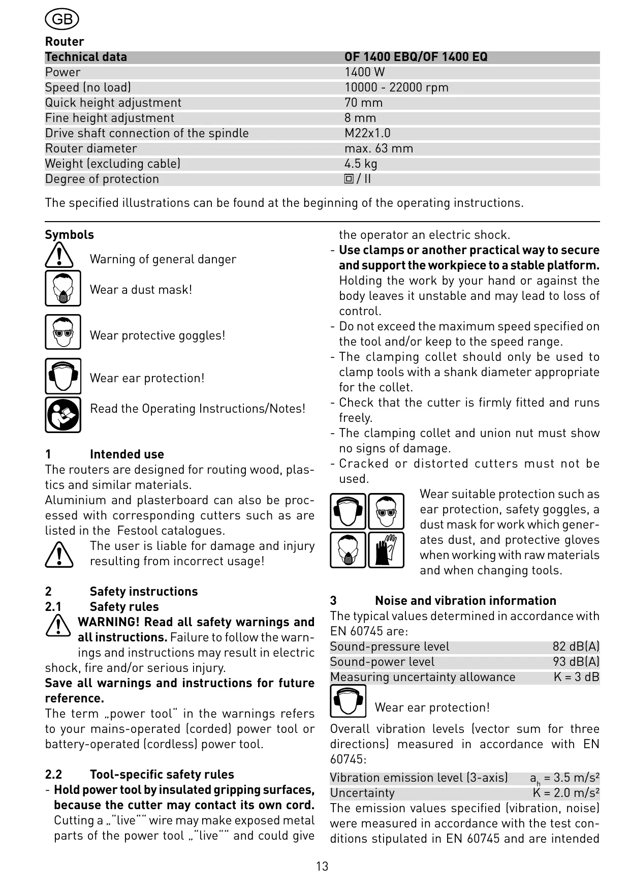
| Technical data | OF 1400 EBQ/OF 1400 EQ |
| Power | 1400 W |
| Speed (no load) | 10000 - 22000 rpm |
| Quick height adjustment | 70 mm |
| Fine height adjustment | 8 mm |
| Drive shaft connection of the spindle | M22x1.0 |
| Router diameter | max. 63 mm |
| Weight (excluding cable) | 4.5 kg |
| Degree of protection | ☐/ ☐ |
The specified illustrations can be found at the beginning of the operating instructions.
Symbols

Warning of general danger
Wear a dust mask!

Wear protective goggles!

Wear ear protection!

Read the Operating Instructions/Notes!
1 Intended use
The routers are designed for routing wood, plastics and similar materials.
Aluminium and plasterboard can also be processed with corresponding cutters such as are listed in the Festool catalogues.

The user is liable for damage and injury resulting from incorrect usage!
2 Safety instructions
2.1 Safety rules

WARNING! Read all safety warnings and all instructions. Failure to follow the warnings and instructions may result in electric, fire and/or serious injury.
Save all warnings and instructions for future reference.
The term „power tool“ in the warnings refers to your mains-operated (corded) power tool or battery-operated (cordless) power tool.
2.2 Tool-specific safety rules
- Hold power tool by insulated gripping surfaces, because the cutter may contact its own cord. Cutting a „live“” wire may make exposed metal parts of the power tool „live“” and could give
the operator an electric shock.
- Use clamps or another practical way to secure and support the workpiece to a stable platform.
Holding the work by your hand or against the body leaves it unstable and may lead to loss of control. - Do not exceed the maximum speed specified on the tool and/or keep to the speed range.
- The clamping collet should only be used to clamp tools with a shank diameter appropriate for the collet.
- Check that the cutter is firmly fitted and runs freely.
- The clamping collet and union nut must show no signs of damage.
- Cracked or distorted cutters must not be used.

Wear suitable protection such as ear protection, safety goggles, a dust mask for work which generates dust, and protective gloves when working with raw materials and when changing tools.
3 Noise and vibration information
The typical values determined in accordance with EN 60745 are:
Sound-pressure level 82 dB(A)
Sound-power level 93 dB(A)
Measuring uncertainty allowance K = 3 ~dB

Wear ear protection!
Overall vibration levels (vector sum for three directions) measured in accordance with EN 60745:
Vibration emission level (3-axis) a_b = 3.5 ~m / s^2
Uncertainty K = 2.0m / s^2
The emission values specified (vibration, noise) were measured in accordance with the test conditions stipulated in EN 60745 and are intended
for machine comparisons. They are also used for making preliminary estimates regarding vibration and noise loads during operation. The emission values specified refer to the main applications for which the power tool is used.
If the electric power tool is used for other applications, with other tools or is not maintained sufficiently prior to operation, however, the vibration and noise load may be higher when the tool is used. Take into account any machine idling times and downtimes to estimate these values more accurately for a specified time period. This may significantly reduce the load during the machine operating period.
4

Power supply and start-up
The line voltage and frequency must correspond with the data on the ratings plate!
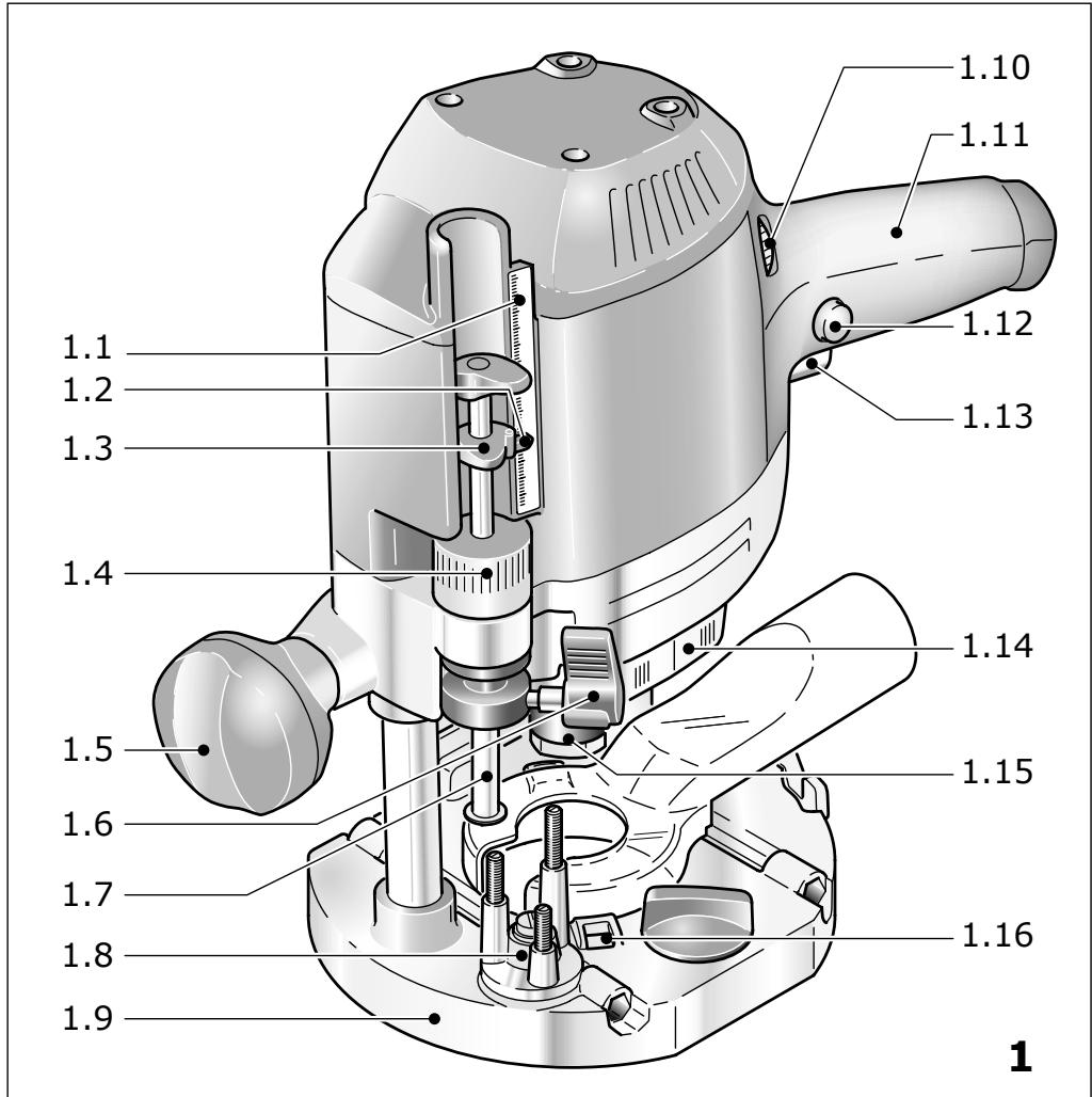
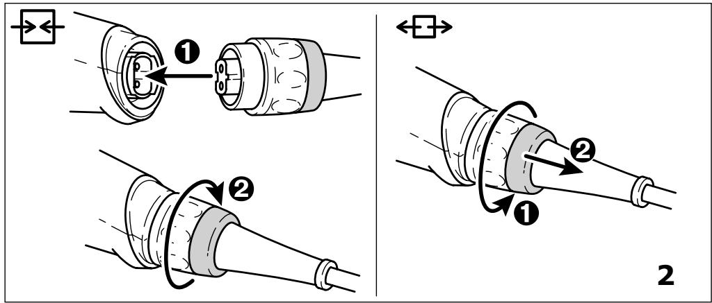
Switch (1.13) serves as an On/Off switch ( l = 0n / 0 = 0ff ). It may be latched with the locking knob on the side (1.12) for continuous operation. Pressing the switch again releases the lock. See Fig. 2 for connection and disconnection of the power cable.
5
Machine settings

Always remove the power supply plug from the socket before carrying out any work on the machine.
5.1 Electronics
Do not operate the tool if the electronics are faulty as this can lead to the tool operating at excessive speeds. If the start-up is not smooth or speed adjustment is not possible, this indicates that the electronics are faulty.

The OF 1400 EBQ, OF 1400 EQ features full-wave electronics with the following properties:
Smooth start-up
The smooth start-up ensures the router starts up jolt-free.
Speed adjustment
You can regulate the speed steplessly between 10000 and 22000min^-1 using the adjusting wheel (1.10). This enables you to optimise the cutting speed to suit the material:
| Material | Cutter diameter [mm] | Recommended cutter material | ||
| 10-25 | 25-40 | 40-60 | ||
| Rotary control setting | ||||
| Hard wood | 6-4 | 5-3 | 3-1 | HW (HSS) |
| Soft wood | 6-5 | 6-3 | 4-1 | HSS (HW) |
| Laminated chipboard | 6-5 | 6-3 | 4-2 | HW |
| Plastic | 6-4 | 5-3 | 2-1 | HW |
| Aluminium | 3-1 | 2-1 | 1 | HSS (HW) |
| Plasterboard | 2-1 | 1 | 1 | HW |
Constant speed
The pre-selected speed remains constant whether the machine is in operation or in neutral position.
Temperature control
If the motor temperature becomes too high, the power supply and speed are reduced. The tool then only runs with reduced power to enable rapid cooling by means of the motor ventilation. After cooling down, the tool accelerates again automatically.
Brake (OF 1400 EBQ)
The OF 1400 EBQ has an electronic brake which brings the spindle with tool to a standstill within approx. 2 seconds of the tool being switched off.
5.2 Changing tools
You can turn the machine upside down when changing the tool.
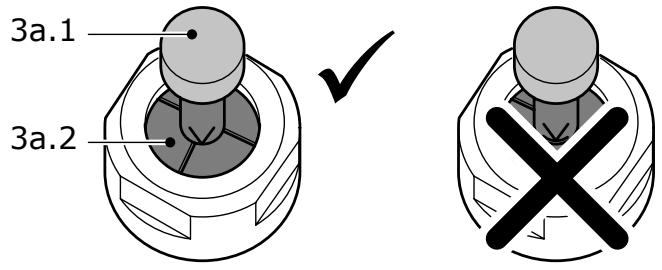
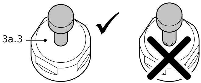
a) Inserting the tool
- Insert the router into the open clamping collet as far as possible, but at least up to the mark () on the router shank. If the collet (3a.2) is not visible because it is blocked by the union nut (3a.3), the milling tool (3a.1) must be inserted into the collet at least far enough that the marker no longer overlaps with the union nut.
- Press the switch (1.14) for locking the spindle on the right-hand side.
- Tighten the locking nut (1.15) with a 24 mm open-end spanner.
Note: the spindle lock only blocks the motor spindle in one direction of rotation at any one time. Therefore when the nut is undone or tightened, the wrench does not need to be offset but can be moved back and forth like a ratchet.
b) Removing the tool
- Press the switch (1.14) for locking the spindle on the left-hand side.
- Loosen the locking nut (1.15) using a 24 mm open-ended spanner until a resistance is felt. Overcome this resistance by turning the open-ended spanner even further.
- Remove the cutter.
5.3 How to change the clamping collet
Clamping collets are available for following shank diameters: 6.0 mm, 6.35 mm, 8 mm, 9.53 mm, 10 mm, 12 mm, 12.7 mm (order numbers see Festool catalogue or Internet „www.festool.com”).
- Fully unscrew the nut (1.15) and remove from spindle together with the clamping collet.
- Insert a new clamping collet with nut into the spindle and slightly tighten the nut. Do not tighten the nut until a milling cutter has been fitted.
5.4 Adjusting the milling depth
The milling depth is adjusted in three stages:
a) Setting the zero point
- Open the clamping lever (1.6) so that the stop cylinder (1.7) can move freely.
- Place the router with router table (1.9) onto a smooth surface. Open the rotary knob (1.5) and press the machine down until the milling cutter rests on the base.
- Clamp the machine in this position by tightening the rotary knob (1.5).
- Press the stop cylinder against one of the three sensing stops of the pivoted turret stop (1.8).
The individual height of each sensing stop can be adjusted with a screwdriver:
| Sensing stop | min. height/max. height |
| A | 38 mm/44 mm |
| B | 44 mm/54 mm |
| C | 54 mm/67 mm |
- Push the pointer (1.3) down so that it shows 0 mm on the scale (1.1).
If the base position is incorrect, this can be adjusted with the screw (1.2) on the indicator.
b) Setting the milling depth
The desired milling depth can be set either with the quick depth adjustment or with the fine depth adjustment.
- Quick depth adjustment: Pull the stop cylinder (1.7) up until the pointer shows the desired milling depth. Clamp the stop cylinder in this
position with the clamping lever (1.6).
- Fine depth adjustment: Clamp the stop cylinder with the clamping lever (1.6). Set the desired milling depth by turning the adjusting wheel (1.4) in. Turn the adjusting wheel to the next mark on the scale to adjust the milling depth by 0.1 mm. One full turn adjusts the milling depth by 1 mm. The maximum adjustment range with the adjusting wheel is 8 mm.
c) Increasing the milling depth
- Open the rotary knob (1.5) and press the tool down until the stop cylinder touches the sensing stops.
- Clamp the machine in this position by tightening the rotary knob (1.5).
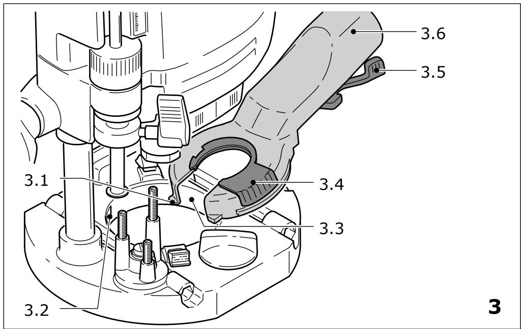
5.5 Dust extraction
Always connect the machine to a dust extractor.
- Fit the extractor hood to the router base by first inserting the two tenons (3.1) on the extractor hood into the recesses (3.2) on the router base, then place the extractor hood on the router base and close the lever (3.5).
- To enable fitting and removing the extractor hood with the router attached, the recess (3.3) in the extractor hood can be opened by turning the segment (3.4). For optimised dust extraction, the recess with the rotating segment must be closed during work.
A Festool dust extractor with an extractor hose diameter of 36 ~mm or 27 ~mm (36 mm recommended due to the reduced risk of clogging) can be connected to the extractor connector (3.6).
KSF-OF chip catcher
Using the KSF-OF chip catcher (sometimes included in the scope of delivery), the efficiency of the extraction can be increased when routing edges.
Installation is similar to that of the copying ring (fig. 8).
The hood can be cut off along the grooves using a hacksaw and can thus be reduced in size. The chip catcher can then be used for interior radiuses up to a minimum radius of 40 mm .
6 Working with the machine
Always secure the workpiece in such a manner that it cannot move while being sawed.


The machine must always be held with both hands by the designated handles (1.5, 1.11).
For work that generates dust, wear a dust mask.
Always advance the router in the direction opposite to the direction of rotation of the cutter (counter-routing)!
When routing (ensure feed direction of power tool is the same as cutting direction of tool, Fig. 9).
6.1 Aluminium processing

When processing aluminium, the following measures must be taken for safety reasons:
- Pre-connect a residual current circuit-breaker (FI, PRCD).
- Connect the machine to a suitable dust extractor.
- Clean tool regularly of dust accumulations in the motor housing.

Wear protective goggles.
6.2 Freehand routing
Freehand routing is the method normally used for lettering or shapes, and for routing edges using cutters with a guide pin or ring.
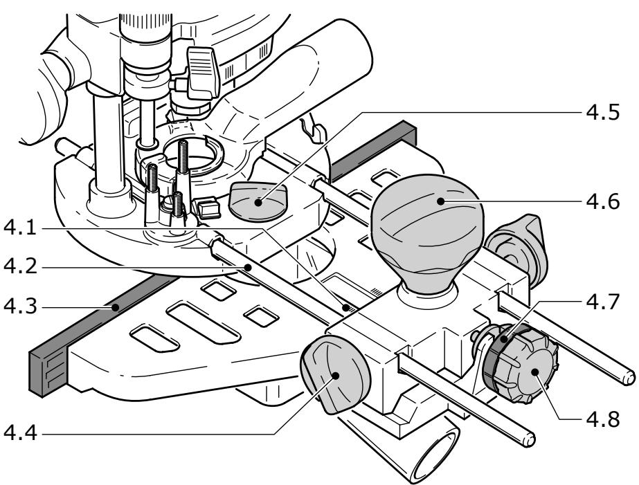
6.3 Routing with the parallel guide
The parallel guide (4.2) supplied can be used for routing parallel to the edge of the workpiece.
- Secure both guide rods (4.2) with the two rotary knobs (4.4) on the side stop.
- Insert the guide rods into the grooves on the router base to the required distance and secure them by turning the rotary knob (4.5).
- Fine adjustment: Unscrew the rotary knob (4.6) to make fine adjustments with the adjusting wheel (4.8). The scale ring (4.7) has a 0.1 mm scale for this purpose. If the adjusting wheel is held secure, the scale ring can be turned separately and set to „Zero". The millimetre scale (4.1) on the main casing is useful when making larger adjustments. Tighten the rotary knob (4.6) again on completion of any fine adjustments.
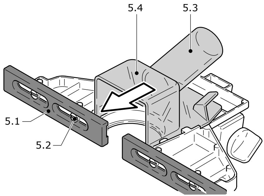
- Adjust both guidance jaws (4.3, 5.1) so that they are approx. 5 ~mm from the router. To do this, undo screws (5.2) and tighten again after completing the adjustments.
- As shown in Fig. 5, slide the extractor hood (5.4) from behind until it latches into place on the side stop. You can connect an extractor hose with a diameter of 27 ~mm or 36 ~mm to the extractor
connector (5.3).
6.4 Routing with the FS guide system
The guide system, available as an accessory, facilitates routing straight grooves.
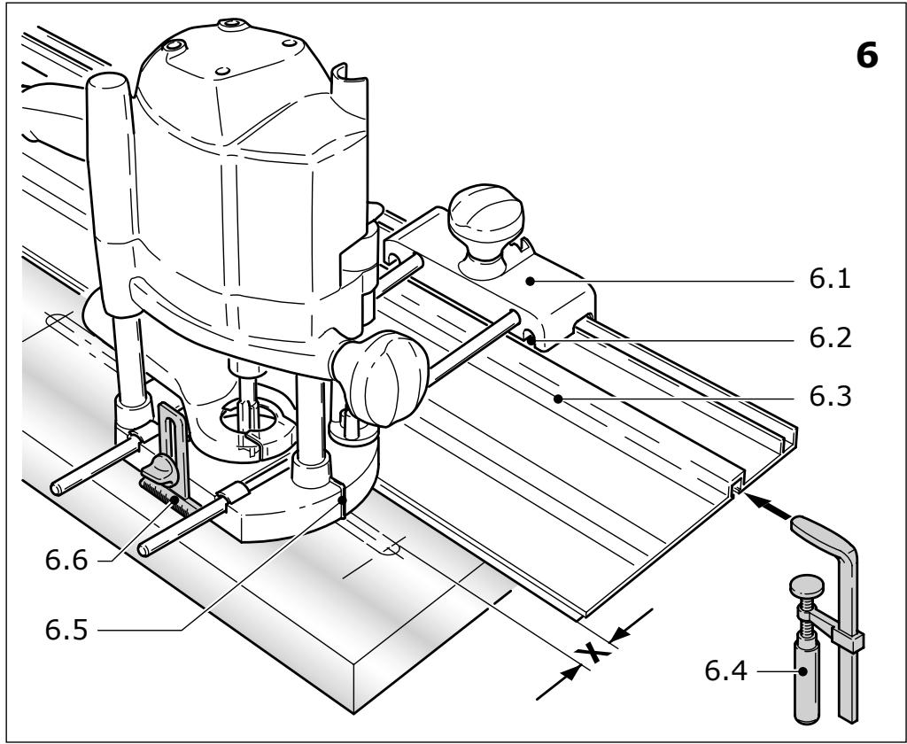
- Fasten the guide stop (6.1) to the platen with the guide rails of the parallel guide.
- Fasten the guide rail (6.3) with FSZ screw clamps (6.4) to the workpiece. Make sure that the safety distance X (Fig. 6) of 5mm between the front edge of the guide rail and cutter or groove is observed.
- Place the guide stop onto the guide rail as shown in Fig. 6. To ensure a backlash-free guidance of the router stop you can adjust two guide cheeks with a screwdriver through the side openings (6.2).
- Screw the height-adjustable support (6.6) of the router table's threaded bore in such a way that the underside of the router table is parallel to the surface of the workpiece.
When working with marking-up lines, the marks on the platen (6.5) and the scale on the support (6.6) show the centre axis of the cutter.
Fine adjustment
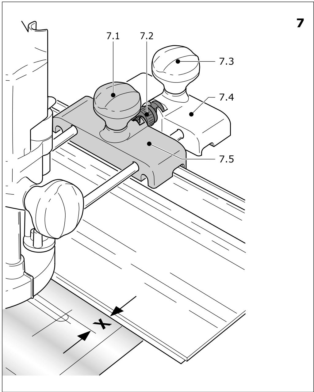
Distance X can be adjusted precisely with the fine adjuster (7.5, Accessory).
- Fit the fine adjuster (7.5) between the tool and the guide stop on the guide rails.
- Insert the adjusting wheel (7.2) into the guide stop as shown in Fig. 7.
- Screw the adjusting wheel (7.2) into the nut on the fine adjuster.
- To adjust distance X, unscrew the rotary knob [7.1] on the guide stop and tighten the rotary knob [7.3] on the fine adjuster.
- Adjust to the required distance X by turning the adjusting wheel (7.2), and then tighten the rotary knob (7.1) on the guide stop.
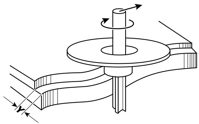
6.5 Copy cutting
A copying ring or the copying device is used to exactly reproduce existing workpieces (both available as accessories).
a) Copying ring
When choosing the size of the copying ring makes sure that the cutter used fits through the ring's opening.
The distance Y (Fig. 9) between the workpiece and template is calculated by
$$ Y = \left(\varnothing \text {c o p y i n g r i n g -} \varnothing \text {c u t t e r}\right) $$
2
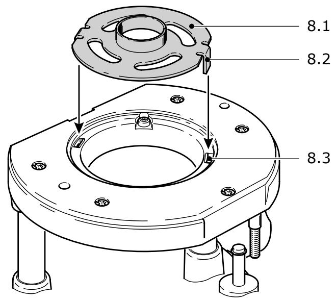
- Secure the copying ring (8.1) to the router base by inserting both tenons (8.2) into the recesses (8.3).
- To loosen the copying ring, press both buttons (1.16) inwards simultaneously.
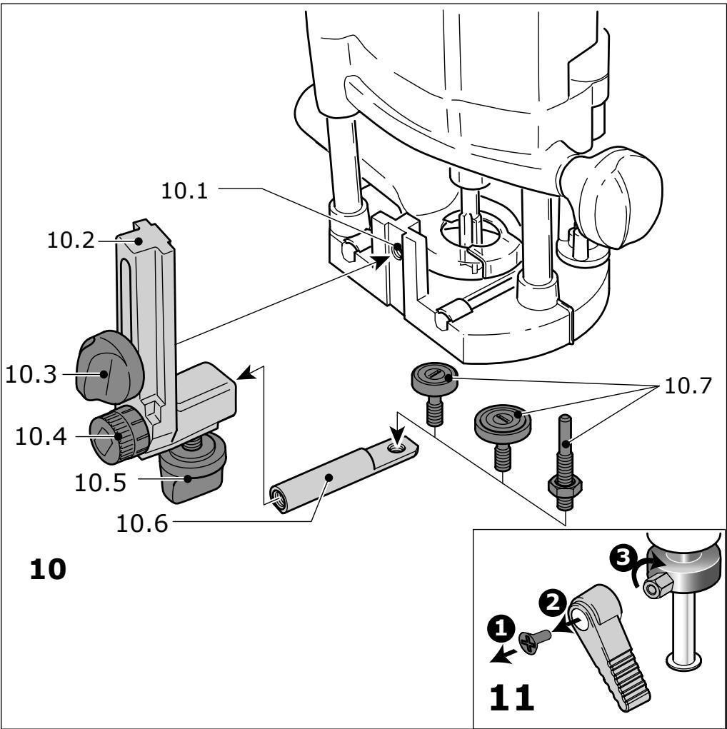
b) Copying device
The angle arm WA-OF (10.2) and copier scanning set KT-OF, consisting of roller holder (10.6) and three copying rollers (10.7), are required for the copying device.
- Screw the angle arm at the desired height in the platen's threaded bore (10.1) with the rotating knob (10.3).
- Fit a copying roller in the roller holder and bolt this to the angle arm with the rotating knob (10.5). Make sure that the copying roller and cutter have the same diameter!
- Turn the adjusting wheel (10.4) to adjust the distance between the copying roller and cutter axis.
7 Accessories

For your own safety, use only original Festool accessories and spare parts.
Festool offers extensive accessories that enable you to use your machine effectively for a wide variety of applications, e.g.: routing circle, guide rails with rows of holes, routing aid, router base for bench-mounted use.
The accessory and tool order number can be found in the Festool catalogue or on the Internet under „www.festool.com".
8 Maintenance and care

Always remove the power supply plug from the socket before carrying out any work on the machine.

All maintenance and repair work which requires the motor casing to be opened may only be carried out by an authorised service centre.
The cool air openings in the motor casing must always be kept clean and unobstructed to ensure air circulation.
The tool is fitted with special motor brushes with an automatic cut-out. When the brushes become worn the power supply is shut off automatically and the tool comes to a standstill.
To alter the position of the clamping lever (see Fig. 11):
- Release the screw.
- Remove the clamping lever and tighten the
hexagon screw.
- Insert the clamping lever again in the desired position and lock it with the screw.
9 Disposal
Do not throw the power tool in your household waste! Dispose of machines, accessories and packaging at an environmentally-responsible recycling centre. Observe the valid national regulations.
EU only: European Directive 2002/96/EC stipulate that used electric power tools must be collected separately and disposed of at an environmentally responsible recycling centre.
10 Warranty
Our equipment is under warranty for at least 12 months with regard to material or production faults in accordance with national legislation. In the EU countries, the warranty period is 24 months (an invoice or delivery note is required as proof of purchase). Damage resulting from, in particular, normal wear and tear, overloading, improper handling, or caused by the user or other damage caused by not following the operating instructions, or any fault acknowledged at the time of purchase, is not covered by the warranty. Damage caused by the use of non-original accessories and consumable material (e.g. sanding pads) is also excluded. Complaints will only be acknowledged if the equipment has not been dismantled before being sent back to the suppliers or to an authorised Festool customer support workshop. Store the operating instructions, safety notes, spare parts list and proof of purchase in a safe place. In addition, the manufacturer's current warranty conditions apply.
Note
We reserve the right to make changes to the technical data contained in this information as a result of ongoing research and development work.
REACH for Festool products, their accessories and consumables
REACH is a European Chemical Directive that came into effect in 2007. As “downstream users” and product manufacturers, we are aware of our duty to provide our customers with information. We have set up the following website to keep you updated with all the latest news and provide you with information on all the materials used in our existing products: www.festool.com/reach
Défoncuse
Varning for allman risk!
Bcerda yKpennIte o6pa6aTbIbAeMyIO DeTaJIb TaK, UTO6bl OHa He DBNrIaIacb npH o6pa6oTke.

Bcerda Āperknte MaunHy DByM pykaMn 3a npedHa3HaueHHbIe dIy 3ToIgpykn (1.5, 1.11).