
SR 4000 - Wireless Microphone System AKG - Free user manual and instructions
Find the device manual for free SR 4000 AKG in PDF.

| Product type | Wireless microphone system |
| Brand | AKG |
| Model | SR 4000 |
| Dimensions (L x H x D) | 200 x 44 x 190 mm |
| Net weight | 972 g |
| Power supply | 12 V DC via mains adapter (supplied), typical current consumption 400 mA |
| Frequency range | UHF 650-863 MHz depending on sub-band (650-680, 680-710, 720-750, 760-790, 790-820, 835-863 MHz) |
| Modulation | FM |
| Audio bandwidth | 35 Hz - 20 kHz |
| Signal-to-noise ratio | Typ. 118 dB(A) |
| Audio outputs | Balanced XLR (levels -30, 0, +6 dB) and unbalanced 6.35 mm jack |
| Display | Backlit LCD with indicators for frequency, audio level, RF, transmitter battery |
| Main functions | True Diversity, LOCK/SETUP mode, automatic frequency scan, squelch adjustment, rehearsal function, removable UHF antennas |
| Maintenance | Clean with a soft, slightly damp cloth; do not use solvents |
| Safety | Do not open, do not use in humid environments, unplug before cleaning |
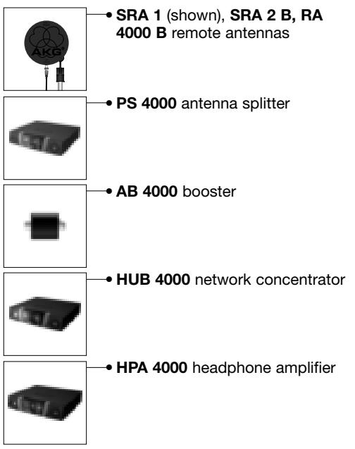
| Optional accessories | Remote antennas SRA 1, SRA 2B, RA 4000 B; antenna amplifier AB 4000; hub HUB 4000; mounting kit RMU 4000 |
| Reparability | Repair only by authorized technical personnel; no user-serviceable parts |
Frequently Asked Questions - SR 4000 AKG
User questions about SR 4000 AKG
0 question about this device. Answer the ones you know or ask your own.
Ask a new question about this device
Download the instructions for your Wireless Microphone System in PDF format for free! Find your manual SR 4000 - AKG and take your electronic device back in hand. On this page are published all the documents necessary for the use of your device. SR 4000 by AKG.
USER MANUAL SR 4000 AKG
wireless microphone system
SR 4000
stationary receiver
C∈⑨
H A Harman International Company
AKG Acoustics GmbH
BodenseestraBe 228, D-81243 Munchen/GERMANY, Tel: (+49 89) 87 16-0, Fax: (+49 89) 87 16-200, www.alkaacoustics.de, e-mail: info@alkaacoustics.de
AKG ACoustics, U.S.
914 Airpark Center Drive, Nashville, TN 37217, U.S.A., Tel: (+1 615) 620-3800, Fax: (+1 615) 620-3875, www.akgusa.com, e-mail: akgusa@harman.com
For other products and distributors worldwide see our website: www.akq.com
Printed in Austria on recycled paper.
05/03/9100U1058
User Instructions. p. 23
Please read the manual before using the equipment!
IMPORTANT NOTE The SR 4000 and Phantom Power
The XLR audio output on the SR 4000 has been designed such that any phantom power voltage to DIN 45 596/IEC 268-15 that may be present at the mixer input will not damage the audio output on the SR 4000 receiver. Some mixers, however, use phantom power circuitry that does not meet this standard (no current limiter). Mixers of this type may cause damage to the audio output on the SR 4000 receiver if you switch both the receiver and the phantom power on the mixer ON first and then connect the receiver audio output to the mixer input.
To prevent damage to the SR 4000 audio output, please remember the following hints:
- Connect all your wireless receivers to LINE inputs only (if available), because LINE inputs do not normally provide phantom power.
- If phantom power on your mixer is switchable individually for each channel, make sure phantom power is OFF on all channels assigned to wireless receivers at all times.
- If phantom power on your mixer is switchable for all channels jointly, be sure to switch both the receiver and phantom power OFF before you connect the receiver audio output to the mixer input. As soon as the cable is plugged in you can switch phantom power on.

Inhaltsverzeichnis
1 Safety and Environment 24
1.1 Safety 24
1.2 Environment 24
2 Description 24
2.1 Introduction 24
2.2 Unpacking 24
2.3 Optional Accessories 24
2.4 General Description 25
2.5 Controls 25
2.5.1 Front Panel 25
2.5.2 Rear Panel 25
2.6 Audio Outputs 25
2.7 Bottom Panel 26
3 Setting Up. 26
3.1 Placing the Receiver 26
3.2 Rack Mounting a Single Receiver 26
3.3 Rack Mounting Two Receivers Side by Side 26
3.4 Connecting the Receiver to a Mixer 26
3.5 Connecting the Receiver to Power 27
3.6 Powering Up 27
3.7 LOCK Mode 27
3.8 Setting Up the Receiver (SETUP mode) 28
3.8.1 Selecting Frequency Groups (Auto Group Setup). 28
3.8.2 Selecting Frequencies for Multichannel Systems (Auto Channel Setup) 29
3.8.3 Selecting Frequencies in the Preset Screen 31
3.8.4 Selecting Frequencies in the Frequency Screen 32
3.8.5 Editing the Receiver Name. 32
3.8.6 Finding Interference Frequencies 33
3.9 Before the Soundcheck 35
3.9.1Rehearsal Function 35
3.9.2 Setting the Squelch Threshold 36
3.10 Multichannel Systems 37
4 Operating Notes. 37
4.1 Selecting Modes 37
4.2 Selecting Screens. 37
4.2.1 LOCK Mode 37
4.2.2 SETUP Mode 37
4.3 Advanced Functions 38
4.3.1 NAME 38
4.3.2 STATUS 38
4.3.3 THRESH 39
4.3.4 INFO 40
5 Cleaning. 41
6 Troubleshooting 41
7 Specifications 42
FCC Statement
This equipment has been tested and found to comply with the limits for a Class B digital device, pursuant to Parts 74, 15, and 90 of the FCC Rules. These limits are designed to provide reasonable protection against harmful interference in a residential installation. This equipment generates, uses, and can radiate radio frequency energy and, if not installed and used in accordance with the instructions, may cause harmful interference to radio communications. However, there is no guarantee that interference will not occur in a particular installation. If this equipment does cause harmful interference to radio or television reception, which can be determined by turning the equipment off and on, the user is encouraged to try to correct the interference by one or more of the following measures:
Reorient or relocate the receiving antenna.
- Increase the separation between the equipment and the receiver.
- Connect the equipment into an outlet on a circuit different from that to which the receiver is connected.
- Consult the dealer or an experienced radio/TV technician for help.
Shielded cables and I/O cords must be used for this equipment to comply with the relevant FCC regulations.
Changes or modifications not expressly approved in writing by AKG Acoustics may void the user's authority to operate this equipment.
This device complies with Part 15 of the FCC Rules. Operation is subject to the following two conditions:
(1) this device may not cause harmful interference, and (2) this device must accept any interference received, including interference that may cause undesired operation.
1.1 Safety
- Do not spill any liquids on the equipment and do not drop any objects through the ventilation slots in the equipment.
- The equipment may be used in dry rooms only.
- The equipment may be opened, serviced, and repaired by authorized personnel only. the equipment contains no user-serviceable parts.
- Before connecting the equipment to power, check that the AC mains voltage stated on the supplied power supply is identical to the AC mains voltage available where you will use the equipment.
- Operate the equipment with the supplied power supply with an output voltage of 12 VDC. Using adapters with an AC output and/or a different output voltage may cause serious damage to the unit.
- If any solid object or liquid penetrates into the equipment, shut down the sound system immediately. Disconnect the power supply from the power outlet immediately and have the equipment checked by AKG service personnel.
- If you will not use the equipment for a long period of time, disconnect the power supply from the power outlet. Please note that the equipment will not be fully isolated from power when you set the power switch to OFF.
- Do not place the equipment near heat sources such as radiators, heating ducts, or amplifiers, etc. and do not expose it to direct sunlight, excessive dust, moisture, rain, mechanical vibrations, or shock.
- To avoid hum or interference, route all audio lines, particularly those connected to the microphone inputs, away from power lines of any type. If you use cable ducts, be sure to use separate ducts for the audio lines.
- Clean the equipment with a moistened (not wet) cloth only. Be sure to disconnect the power supply from the power outlet before cleaning the equipment! Never use caustic or scouring cleaners or cleaning agents containing alcohol or solvents since these may damage the enamel and plastic parts.
11.Use the equipment for the applications described in this manual only. AKG cannot accept any liability for damages resulting from improper handling or misuse.
1.2 Environment

- The power supply will draw a small amount of current even when the equipment is switched off. To save energy, disconnect the power supply from the power outlet if you will leave the equipment unused for a long period of time.
- When scrapping the equipment, separate the case, circuit boards, and cables, and dispose of all components in accordance with local waste disposal rules.

2 Description
2.1 Introduction
Thank you for purchasing an AKG product. This Manual contains important instructions for setting up and operating your equipment. Please take a few minutes to read the instructions below carefully before operating the equipment. Please keep the Manual for future reference. Have fun and impress your audience!
2.2 Unpacking
1 SR 4000 receiver
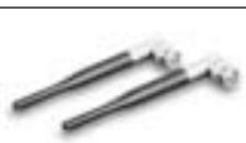
2 UHF antennas

1 AC adapter for 12 VDC

1 RMU 4000 rack mounting kit
Check that the packaging contains all of the components listed above. Should anything be missing, please contact your AKG dealer.
2.3 Optional Accessories
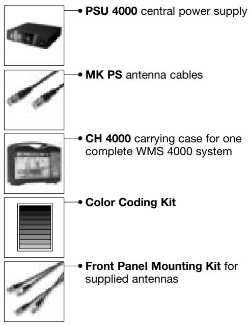
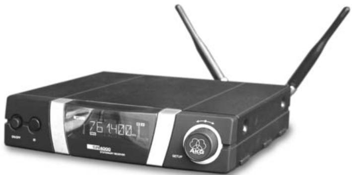
The SR 4000 is a stationary True Diversity receiver for use with all WMS 4000 transmitters. The SR 4000 operates in a subband up to 30MHz wide of the 650MHz to 863MHz UHF carrier frequency band. Within the subband, you can either set the carrier frequency directly in 25-kHz increments or select one of the Subchannels of the Preset Frequency Groups of your receiver.
A backlit LCD display indicates all important parameters including the receiving frequency, audio level, RF level, current operating mode, and remaining transmitter battery life.
The receiver provides two operating modes:
In LOCK mode, all setup functions are electronically locked to prevent parameters from being readjusted unintentionally during a performance or lecture. The "LOCK" label on the display indicates the receiver is in LOCK mode.
SETUP mode allows you to adjust and save all receiver parameters. In SETUP mode, the "LOCK" label disappears.
The receiver provides both a balanced XLR and an unbalanced 1/4" audio output.
You can use the receiver as a standalone unit or install it in a 19" rack using the supplied RMU 4000 Rack Mounting Kit.
2.4 General Description
The display is protected from scratching by a transparent foil. You can peel the foil off at any time.
1 POWER: Switches power to the unit on or off.
2 LCD Display: The receiver provides a backlit LCD display: The display indicates all receiver parameters:
2.5 Controls
2.5.1 Front Panel
Refer to fig. 1.
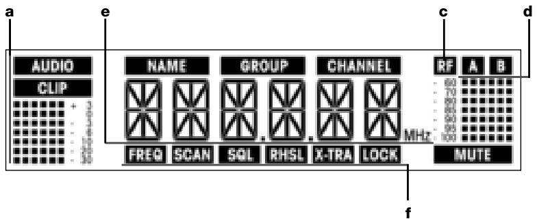
a Audio level
b Preset/Receiver Name, Frequency Group, Subchannel (shown in Preset and NAME screens only)
c Received signal field strength
d Diversity indicators (A/B)
e Alphanumeric display of current setting or transmitter battery capacity
f Parameter to be adjusted, mode
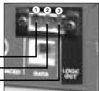
3 SETUP: Sets the various parameters of the receiver. The SETUP control has the following functions:
In LOCK mode:
Turn CW or CCW to the stop: Scroll through the Frequency screen, Preset screen (only available if a Preset has been stored preciously), receiver name, and battery status (battery capacity in hours) displays.
Long push: Toggles between LOCK and SETUP modes.
- In SETUP mode only:
Short push: Calls up a parameter for adjustment or confirms a selected value.
Turn CW to the stop to select a menu item or increase a parameter value.
Turn CCW to the stop to select a menu item or decrease a parameter value.
4 ID: If you use the receiver within a multichannel system, you can color-code each channel. Remove the transparent ID cap, replace the black plastic tab with a different-color tab from the optional Color Coding Kit, and replace the transparent cap.
5 LED ring (green/red): If one or more warning functions are activated (see section 4.3.2), the LED ring will be lit red when a critical condition occurs. As long as all parameters are within their normal ranges, the LED ring is lit green.
6 DC ONLY: Locking DC input for connecting to the supplied power supply.
7 ANTENNA A/B: 2 BNC sockets for connecting the supplied UHF antennas (7a) or optional remote antennas.
8 BALANCED: Balanced 3-pin XLR audio output for connecting to, e.g., a microphone input on the mixing console.
9 UNBALANCED: Unbalanced 1/4'' TS audio output jack for connecting to, e.g., a guitar amplifier.
10 Output level switch: Slide switch for matching the BALANCED output level to the input gain of the equipment connected to the receiver. The switch has three positions: -30, 0, and +6 dB. The UNBALANCED output level is not adjustable.
11 DATA: Data output for connecting to a computer.
12 LOGIC OUT: Logic output for controlling external functions (e.g., channel muting on an AS 8 automatic mixer). This 3-pin Phoenix connector provides the following signals:
1 Receiver audio output on (0 V) / muted (5 V)
2 Logic ground
3 Transmitter batteries o.k. (0 V) / nearly dead (5 V)
2.5.2 Rear Panel
Refer to fig. 2.
2.6 Audio Outputs
Refer to fig. 2.
2.7 Bottom Panel
The receiver type plate 18 indicating available carrier frequency ranges and approval information is affixed to the bottom panel.

3 Setting Up
Important! Prior to setting up the receiver, check that the AC mains voltage stated on the supplied power supply is identical to the AC mains voltage available where you will use your system. Using the power supply with a different AC voltage may cause damage to the unit.
Important! Prior to setting up your WMS 4000, check that the transmitter and receiver are tuned to the same frequency. Refer to sections 3.8.1 through 4 and the transmitter manual(s).
Note: In the display illustrations in the following sections, flashing characters are identified by angle symbols >'' and < . All the values shown are examples of possible settings.
3.1 Placing the Receiver Reflections off metal parts, walls, ceilings, etc. or the shadow effects of musicians and other people may weaken or cancel the direct transmitter signal. For best results, place the receiver or remote antennas as follows:
- Place the receiver/antennas near the performance area (stage). Make sure, though, that the transmitter will never get any closer to the receiver than 10 ft (3 m). Optimum separation is 16 ft. (5 m).
- Check that you can see the receiver from where you will be using the transmitter.
- Place the receiver at least 5 ft. (1.5 m) away from any big metal objects, walls, scaffolding, ceilings, etc.
Note: You can either use the receiver freestanding or mount it in a 19" rack using the supplied RMU 4000 rack mounting kit.
3.2 Rack Mounting a Single Receiver 1. Unscrew the four rubber feet ① from the receiver bottom panel. 2. Unscrew the two fixing screws ② from each side panel. Refer to fig. 3. 3. Use the fixing screws ② to screw the short bracket ③ to one side panel and the long bracket ④ to the other side panel. The brackets are contained in the RMU 40/div. rack mounting kit. 4. Install the receiver in your rack.
3.3 Rack Mounting Two Receivers Side by Side Mounting kits.
- Unscrew the four rubber feet ① from each receiver's bottom panel and remove the screws ⑤ from the rubber feet ①.
- Unscrew the two fixing screws 2 from the right-hand side panel of one receiver and from the left-hand side panel of the other receiver.
- Remove the plastic covers 3 from the side panels with the fixing screws 2 still on.
- Insert one connecting strip 4 into each free slot in the side panel of the first receiver, making sure to align the hole in each connecting strip 4 with the appropriate threaded hole in the receiver bottom panel.
- Fix the three connecting strips 4 on the first receiver using three of the screws 5 you removed from the rubber feet.
- To join the two receivers, slide the connecting strips 4 on the first receiver through the free slots in the side panel of the second receiver. Make sure to align the hole in each connecting strip 4 with the appropriate threaded hole in the bottom panel of the second receiver.
- Fix the connecting strips ④ on the second receiver using the three screws ⑤ you removed from the rubber feet.
- Screw a short bracket to the outer side panel of each receiver using for each bracket two of the screws you removed from the receiver side panels.
- Install the receivers in your rack.
Note: Be sure to keep the remaining screws ⑤ for later use.
3.4 Connecting the Receiver Connect the audio output to the desired input: to a Mixer - BALANCED socket 串 - XLR cable - microphone input: set output level switch 10 to "-30 dB". Refer to figs. 2 and 5. - BALANCED socket 串 - XLR cable - line input: set output level switch 10 to "0 dB" or "+"6 dB". - UNBALANCED jack 串 - 1/4" jack cable - unbalanced 1/4" microphone or line input jack.
3.5 Connecting the Receiver to Power Refer to fig. 6. 1. Check that the AC mains voltage stated on the supplied power supply is identical to the AC mains voltage available where you will use your system. Using the power supply with a different AC voltage may cause damage to the unit.
2. Plug the feeder cable 1 on the supplied power supply into the DC ONLY socket 2 on the receiver rear panel and screw down the DC connector 3.
3. Plug the power cable on the power supply into a convenient power outlet.
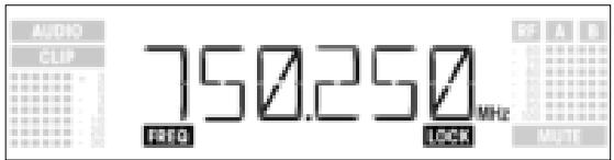
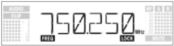
- Press the front panel POWER switch to switch power to the receiver ON. Pressing POWER automatically places the receiver in Lock mode, and the display will indicate the currently active frequency in MHz and the "LOCK" label:
If power to the transmitter is OFF or the RF level at the antennas is zero for some other reason (e.g., shadow effects), the "MUTE" label will appear on the display and the audio output will be muted. If the antennas receive RF signal, the bargraph meter below "A" and "B" indicates the field strength of the signal received by the active antenna.
The bargraph below "AUDIO" indicates the audio level. "CLIP" illuminates to indicate audio signal clipping. 2. After approximately 5 seconds, the display will change to the last active status screen before powering down.
In LOCK mode, the receiver receives the transmitter signal. The receiver is electronically locked so you cannot make any adjustments. You may, however, call up the various status screens one after the other. The "LOCK" label is shown on the display.
To enter Lock mode, either switch power to the receiver ON or (if the receiver is ON and the "LOCK" label is not displayed) press and hold the SETUP control until the "LOCK" label appears.
Approximately 15 seconds after the frequency in MHz has appeared, the display will change to the last active status screen before powering down. The following status screens are stored in memory on powering down and displayed after powering up: Preset, Frequency, Name.
To scroll through the following status screens, turn the SETUP control CW or CCW:
- Preset (comes up only if a Preset has been saved): Carrier frequency shown as Subchannel number within a Frequency Group
- Frequency: Carrier frequency in MHz. (This screen is always available, even if no Preset has been saved.)
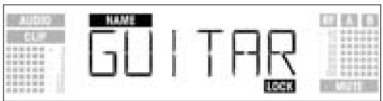
- Name: Current receiver name (comes up only if you have previously named the receiver)
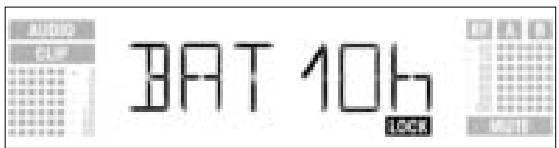
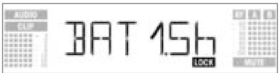
- Battery: Transmitter battery capacity in hours. (This screen will not be saved on powering down.) The way the capacity is indicated depends on the remaining battery life:
- More than 10 hours:
- Less than 10 hours:
3.6 Powering Up
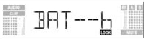
- If no battery information is received or the information is invalid, the following message appears on the display:
3.8 Setting Up the Receiver (SETUP Mode)
In SETUP mode, the electronic lock is disabled so you can adjust all receiver parameters. The "LOCK" label is not shown.
- To enter SETUP mode, press and hold the SETUP control until the "LOCK" label disappears.
-
Turn the SETUP control CW or CCW to select the desired setup screen. The following setup screens are available:
-
Auto Group Setup
- Auto Channel Setup for selecting the receiving frequency*
- Preset
- Frequency
- Name
- Environment Scan
- Squelch Threshold
- Rehearsal
-Extra
*Note:
If your system has only a single channel, we recommend using the Auto Group Setup screen (section 3.8.1) to set the frequency.
To set frequencies for a multichannel system, use the Auto Channel Setup screen (section 3.8.2).
- To return to LOCK mode, press and hold the SETUP control until the "LOCK" label appears on the display.
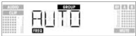
3.8.1 Selecting Frequency Groups (Auto Group Setup)
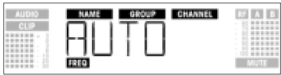
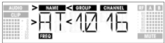
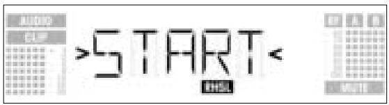
- In SETUP mode, turn the SETUP control CW or CCW as many times as needed to call up this screen:
- Press the SETUP control briefly. The display will change as follows:
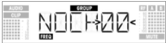
- Turn the SETUP control CW or CCW to select the number of subchannels you need (e.g., "01" for a single-channel system, or "14" for a 14-channel system).
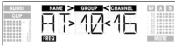
- Press the SETUP control briefly. the display will change as follows:
- Turn the SETUP control CW to select the next Preset or CCW to select the preceding Preset. The Preset names are arranged in alphabetical order.
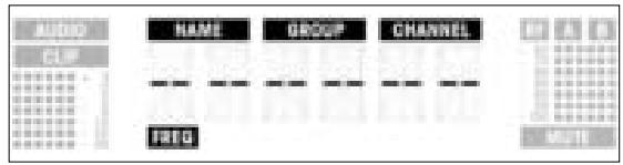
- Press the SETUP control briefly. The receiver will automatically find a Group with the selected number of clean frequencies within the selected Preset and tune to the first clean frequency. During the search, the SETUP control will be disabled, and the display will look like this:
Note:
Clean frequencies are frequencies where the receiver finds no RF signal or an RF signal whose level is lower than the current threshold setting. (Refer to section 4.3.3.)
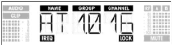
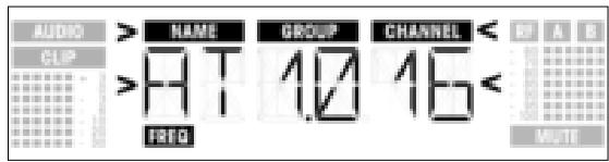
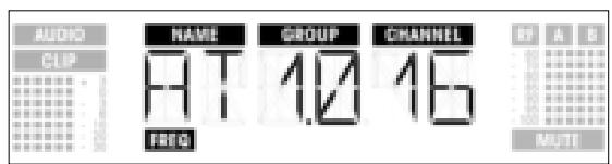
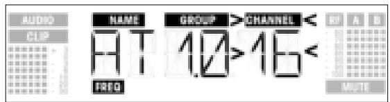
- As soon as the receiver has found a clean frequency, the Subchannel number assigned to this frequency will be displayed. The SETUP control will not respond to turning. The NAME, GROUP, and CHANNEL fields will be flashing:
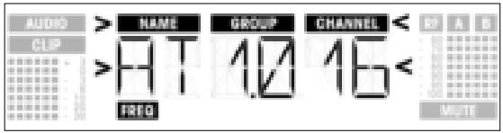
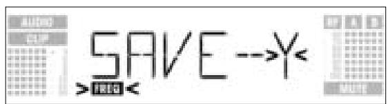
- Press the SETUP control briefly. The display will change as follows:
- To save your setting, press the SETUP control briefly. The display will revert to the Auto Group Setup screen.
- If you'd rather not save your setting, turn the SETUP control CW or CCW. The display will change as follows:
- Press the SETUP control briefly. The display will revert to the Auto Group Setup screen.
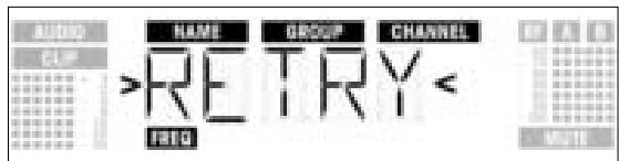
- If the receiver finds no clean frequency, the display will look like this:

- Press the SETUP control briefly. The display will change as follows:
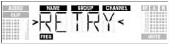
- If you want to try again, press the SETUP control briefly and repeat steps 3 through 6 above.
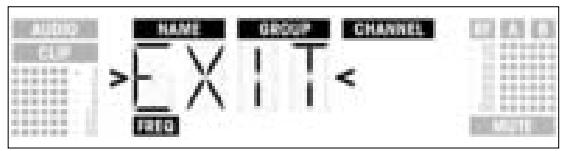
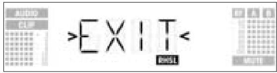
- If you prefer not to start a new frequency search, turn the SETUP control CW or CCW. This will bring up the "EXIT" option:
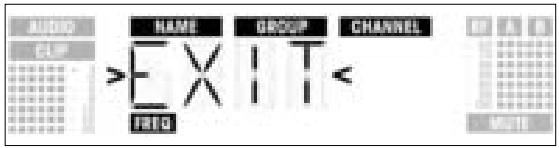
-
Press the SETUP control briefly. The setting will not be saved and the display will revert to the Auto Group Setup screen.
-
Select the frequency of the first receiver using the Auto Group Setup screen (refer to section 3.8.1 above).
- Switch ON any radio microphones, personal monitor transmitters, etc. (including even those made by other manufacturers)! This is the only way to make sure the receiver will find frequencies that will be free of any mutual interference during the performance.
- Tune the transmitter assigned to the receiver to the same frequency that you selected on the receiver and switch power to the transmitter on.
-
Set all other receivers to the same frequency GROUP as the first receiver and use the Auto Channel Setup screen to automatically find the optimum frequency (CHANNEL) for each receiver:
-
In SETUP mode, turn the SETUP control CW or CCW to bring up the following screen:
3.8.2 Selecting Frequencies for Multichannel Systems (Auto Channel Setup)
- Press the SETUP control briefly. The display will change as follows:
- Turn the SETUP control CW or CCW to select the same Preset as the one you selected on the first receiver. Preset names are sorted alphabetically.
- Press the SETUP control briefly. The "GROUP" label on the display will start flashing.
- Turn the SETUP control CW or CCW to select the same Group as the one you selected on the first receiver.
- Press the SETUP control briefly. The receiver will automatically find the next clean frequency. As soon as the receiver has found an interference-free frequency, the Subchannel number assigned to this frequency will be displayed. The SETUP control will not respond to turning. The Preset Name, Group, and Subchannel fields will be flashing:
Note: Clean frequencies are frequencies where the receiver finds no RF signal or an RF signal whose level is lower than the current threshold setting.
Note: Low-number Subchannels are less susceptible to intermodulation than higher-number Subchannels.
- Press the SETUP control briefly. The display will change as follows:

- To save your setting, press the SETUP control briefly. The display will revert to the Auto Channel Setup screen.
- If you'd rather not save your setting, turn the SETUP control CW or CCW. The display will change as follows:
- Press the SETUP control briefly. The display will revert to the Auto Channel Setup screen.
- Tune the transmitter assigned to the receiver to the same frequency that you selected on the receiver and switch power to the transmitter on.
- If the receiver finds no clean frequency, the display will look like this:
- Press the SETUP control briefly. The display will change as follows:
-
To try again, press the SETUP control briefly and repeat steps 2 through 8 above.
-
If you prefer not to start a new frequency search, turn the SETUP control CW or CCW. This will bring up the "EXIT" option:
-
Press the SETUP control briefly. The setting will not be saved and the display will revert to the Preset screen.
-
In SETUP mode, turn the SETUP control CW or CCW to call up this screen:
3.8.3 Selecting Frequencies from the Preset Screen
If, however, you have set the current receiving frequency in the Frequency screen or no Preset has Refer to section 3.8.4. been saved yet, the following screen will appear in the display:
- Press the SETUP control briefly. The display will change as follows:
- Turn the SETUP control CW or CCW to select the desired Preset.
- Press the SETUP control briefly. The display will change as follows:
- Turn the SETUP control CW or CCW to select the desired Frequency Group.
- Press the SETUP control briefly. The display will change as follows:
- Turn the SETUP control CW or CCW to select the desired frequency as a Subchannel of the selected Frequency Group.
- Press the SETUP control briefly. The display will change as follows:
- To save your setting, press the SETUP control briefly. The display will revert to the Preset screen.
- If you'd rather not save your setting, turn the SETUP control CW or CCW. The display will change as follows:
- Press the SETUP control briefly. The display will revert to the Preset screen.
3.8.4 Selecting Frequencies from the Frequency Screen
- In SETUP mode, turn the SETUP control CW or CCW to call up this screen:
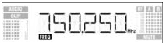
- Press the SETUP control briefly. The display will change as follows:
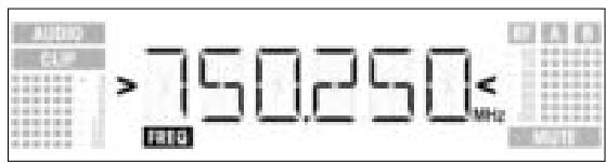
- To select the desired frequency, turn the SETUP control CW or CCW.
- Press the SETUP control briefly. The display will change as follows:
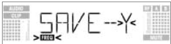
- To save your setting, press the SETUP control briefly. The display will revert to the Frequency screen.
- If you'd rather not save your setting, turn the SETUP control CW or CCW. The display will change as follows:

- Press the SETUP control briefly. The display will revert to the Frequency screen.
3.8.5 Editing the Receiver Name Note:
This screen lets you edit the current name of the receiver. If you have not named the receiver yet or deleted its previous name, this screen will not be available. The EXTRA screen, however, allows you to save a new name at any time (refer to section 4.3.1).
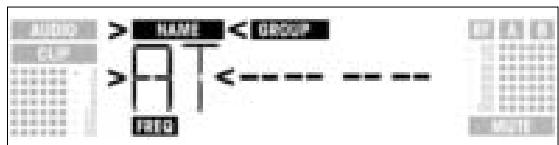
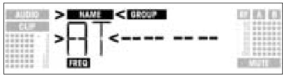
- In SETUP mode, turn the SETUP control CW or CCW to display the current name of the receiver:
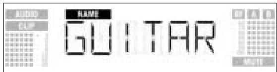
The receiver name may be any combination of six letters and/or numbers.
2. Edit the current name
- Press the SETUP control briefly. The first character will start flashing:

- To change the first character turn the SETUP control CW or CCW.
- Press the SETUP control briefly. The second character will start flashing:
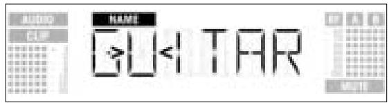
- Repeat the two steps above to change all characters as desired.
3. Save or delete the name
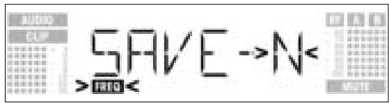
- Press the SETUP control briefly. The display will change as follows:
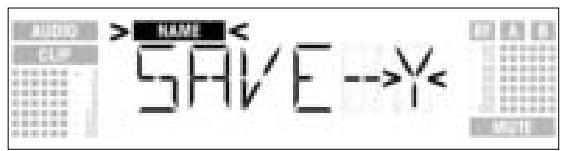
- To save your setting, press the SETUP control briefly. The display will revert to the NAME screen.
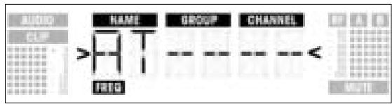
- If you'd rather not save your setting, turn the SETUP control CW. The display will change as follows:
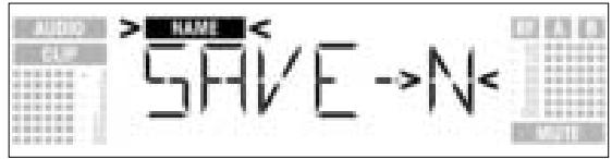
- To delete the current name, turn the SETUP control CW again. This will display the following option:
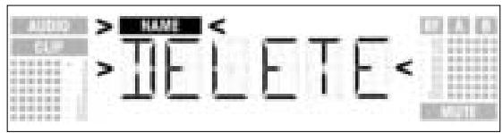
- Press the SETUP control briefly. The display will revert to the NAME screen.
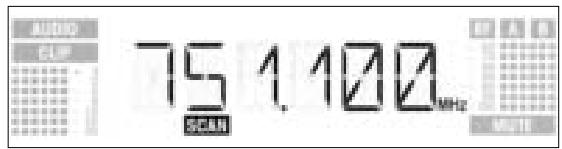
The Environment Scan function automatically searches the receiver's entire frequency band from Start to Stop (see Frequency Tables on page 122) for interference frequencies. During the search, the audio output is muted and the display indicates the frequencies in MHz as they are scanned.
The frequency spacing for the automatic scan is 100kHz . Frequencies whose field strength exceeds the factory-set threshold (or the threshold you may have set using the Threshold function in the EXTRA menu) are defined as interference frequencies and saved in a scan list.
The receiver can store a maximum of eight interference frequencies. As soon as the Stop frequency is reached or the scan list is full, the scan will be stopped automatically.
Venues that are extremely hostile to RF transmission may make it necessary to change the Environment Scan threshold setting. You can change the setting using the THRESH function in the EXTRA menu.
3.8.6 Finding Interference Frequencies
- In SETUP mode, turn the SETUP control CW or CCW to call up this screen:
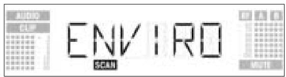
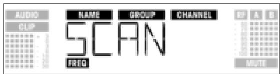
- Press the SETUP control briefly. The display will change as follows:
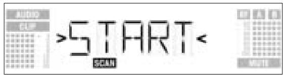
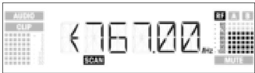
- To start the scan, press the SETUP control briefly. The scan will start and the display will show the frequencies as they are scanned:
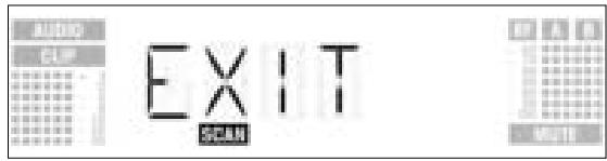
- To exit Environment Scan, turn the SETUP control CW or CCW. The "EXIT" option will appear on the display and start flashing:
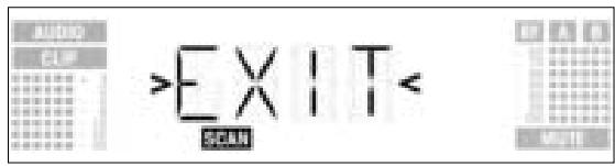
- Press the SETUP control briefly. The display will revert to the Environment Scan screen.
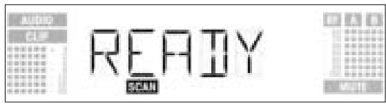
- Once the scan has reached the Stop frequency, the scan is automatically stopped and the message "READY" appears on the display.
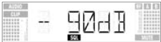
- To view the first item on the scan list, press the SETUP control briefly. To scroll through the other items, turn the SETUP control CW or CCW. An interference source can be a single frequency as in example 1 or a frequency band as in example 2 below. The RF meter on the display indicates the noise level of the scanned frequency or band.
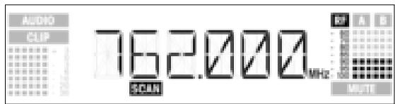
Example 1: A noise level of -90 dB has been found on the receiving frequency of 762 MHz.
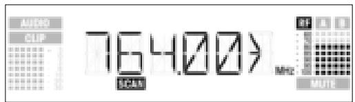
Example 2: A max. noise level of -80 dB has been found in the 764 MHz to 767 MHz band.
The last item on the scan list is the "EXIT" option.
- To scroll through the list again, turn the SETUP control CW or CCW. To return to the Environment Scan screen, press the SETUP control briefly.
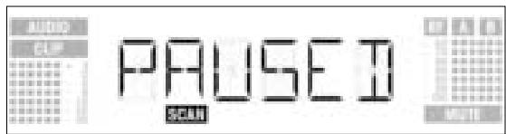
Interrupting the scan
- You can interrupt the scan at any time by pressing the SETUP control briefly. If you do, the message "PAUSED" will appear on the display.
- To view the the scan list, press the SETUP control briefly. You can scroll through the items on the list by turning the SETUP control CW or CCW.
- Press the SETUP control briefly. The display will offer the "CONT" option.
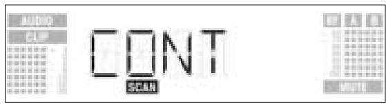
- To resume the scan, press the SETUP control briefly.
If the scan list is full before the Stop frequency has been reached, the scan will be stopped automatically and the message "OVERFL" will appear on the display.
Memory overflow
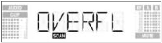
- To view the the scan list, press the SETUP control briefly. You can scroll through the items on the list by turning the SETUP control CW or CCW.
- Press the SETUP control briefly. The display will offer the "CONT" option.
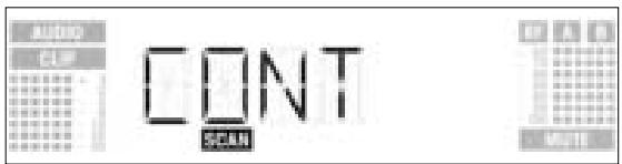
- Press the SETUP control briefly. The scan list will be erased and the scan resumed.
If Environment Scan has found no interference frequencies, the message "CLEAN" will appear on the display.
No interference frequencies
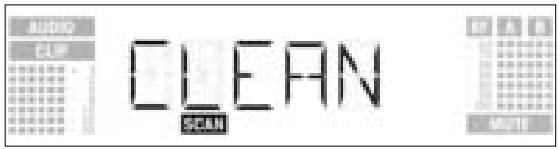
-
Press the SETUP control briefly. The display will revert to the Environment Scan screen.
-
Activate the Rehearsal function on the receiver referring to section 3.9.1 below.
- Move the transmitter around the area where you will use the system to check the area for "dead spots", i.e., places where the field strength seems to drop and reception deteriorates.
If you find any dead spots, try to eliminate them by repositioning the receiver. If this does not help, avoid the dead spots.
- If the received signal is noisy, set the squelch threshold to a level where the noise will stop. (Refer to section 3.9.2.)
3.9 Before the Soundcheck
Never set the squelch threshold any higher than absolutely necessary. The higher the squelch threshold, the lower the sensitivity of the receiver and thus the usable range between transmitter and receiver.
Important!
- The RF meter on the receiver extinguishing and the "MUTE" message appearing mean that no signal is being received or the squelch is active.
Switch the transmitter ON, move closer to the receiver, or set the squelch threshold to the point that the "MUTE" message will disappear and the RF meter come on again.
The Rehearsal function detects a maximum of six dropouts and records the time each dropout occurred, the minimum field strength at each antenna, the field strength ratio between the two antennas as a percentage, and the maximum audio level. The recording will stop automatically afgter 15 minutes (or when the Rehearsal memory is full). You can view the list of results after the recording has stopped.
3.9.1 Rehearsal Function
- In SETUP mode, turn the SETUP control CW or CCW to call up this screen:
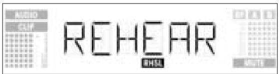
- Press the SETUP control briefly. The display will change as follows:
-
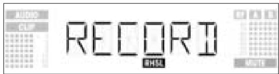
To activate the Rehearsal function, press the SETUP control briefly. The receiver starts testing the radio link and displays the message "RECORD".
-
If you do not wish to start Rehearsal turn the SETUP control CW or CCW to bring up the "EXIT" option.
- Press the SETUP control briefly. The display will revert to the Rehearsal screen.
- During the test, the receiver displays the message "RECORD".
Note: You can stop the test at any time by briefly pressing the SETUP ocontrol.
When the test is completed, the message "READY" or "OVERFL" will appear on the display.
- To view the results, press the SETUP control briefly. The display will show the first item on the result list (example 1).
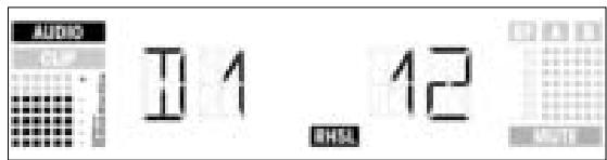
Example 1: Dropout after 12 seconds, maximum audio level: -3 dB.
- To scroll through the result list, turn the SETUP control CW or CCW. The first six of a total of eight memory locations are assigned to dropouts, the last two for reception statistics (examples 2 and 3).
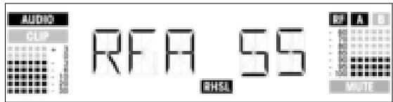
Example 2: Antenna A was active for 55% of the test period. Maximum audio level: -3 dB; minimum field strength at antenna A: -90 dB.
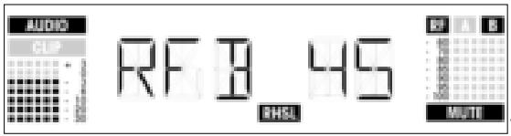
Example 3: Antenna B was active for 45% of the test period. Maximum audio level: -3 dB; minimum field strength at antenna B: less than -100 dB.
-
The last item on the result list is followed (or the first item preceded) by the "EXIT" option.
-
To scroll through the list again, turn the SETUP control CW or CCW.
To return to the Rehearsal screen press the SETUP control briefly.
3.9.2 Setting the Squelch Threshold
- In SETUP mode, turn the SETUP control CW or CCW to call up this screen:
- Press the SETUP control briefly. The current setting, e.g., -90 dB, will be flashing on the display:
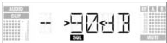
- Turn the SETUP control CW or CCW to select the desired squelch threshold. You can select between "TCSQ" (automatic Tone Code Squelch) and several preset values.
- Press the SETUP control briefly. The display will change as follows:
- To save your setting, press the SETUP control briefly. The display will revert to the Squelch screen.
- If you'd rather not save your setting, turn the SETUP control CW or CCW. The display will change as follows:
-
Press the SETUP control briefly. The display will revert to the Squelch screen.
-
Be sure to assign a separate carrier frequency to each wireless channel (transmitter and receiver).
- To find intermodulation-free carrier frequencies quickly and easily, we recommend using Auto Preset to select all required carrier frequencies from the same Frequency Group within the same Preset.
If reception on the selected carrier frequency is poor, use Auto Channel Setup to find the next clean Subchannel within the selected Frequency Group. Should you find no clean Subchannel, use Auto Group Setup to select a different Frequency Group within the same Preset and selecet a new frequency for each WMS 4000 channel (refer to sections 3.8.1 and 3.8.2).
- Do not operate two or more wireless channels on the same frequency at the same time and location. This would cause unwanted noise due to radio interference.
3.10 Multichannel Systems
Note:
4 Operating Notes

To toggle between LOCK and SETUP modes, press and hold the SETUP control for approximately 1.5 seconds.
When the receiver is in LOCK mode, the "LOCK" label is shown on the display. In SETUP mode, the "LOCK" label is not shown.
4.1 Selecting Modes
In LOCK mode, you can only call up the following status screens:
- Preset
- Frequency
- Name
- Battery life
4.2 Selecting Screens 4.2.1 LOCK Mode
- To call up the status screens in the above order, turn the SETUP control CW. The last screen is followed by the first.
- To call up the status screens in reverse order, turn the SETUP control CCW. The first screen is followed by the last.
The following setup screens are available in SETUP mode:
4.2.2 SETUP Mode
- Auto Group Setup
- Auto Channel Setup
- Preset
- Frequency
- Name
- Environment Scan
- Squelch Threshold
- Rehearsal
-Extra
Each screen provides one or two submenus for you to make your adjustments.
- To call up the setup screens in the above order, turn the SETUP control CW. The last screen is followed by the first.
- To call up the setup screens in reverse order, turn the SETUP control CCW.
The first screen is followed by the last.
- To move from a setup screen to a submenu, press the SETUP control briefly.
4.3 Advanced Functions
The EXTRA screen (refer to section 4.2.2 above) provides the following submenus:
- NAME
- STATUS
-THRESH
-INFO -
EXIT
-
To call up the submenus in the above order, turn the SETUP control CW. The last submenu is followed by the first.
- To call up the submenus in reverse order, turn the SETUP control CCW.
The first submenu is followed by the last. - To call up the adjustment screen for the selected parameter, press the SETUP control briefly.
4.3.1 NAME
- Entering a new name
- Select "NAME" from the EXTRA screen (refer to section 4.3 above). The first character will start flashing:
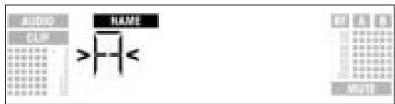
- To change the first character turn the SETUP control CW or CCW.
- Press the SETUP control briefly. The second character will start flashing.
- Repeat the two steps above to change all characters as desired.
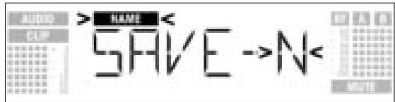
- Saving or deleting a name
- Press the SETUP control briefly. The display will change as follows:
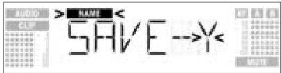
-
To save your setting, press the SETUP control briefly. The display will revert to the Name screen.
-
If you'd rather not save your setting, turn the SETUP control CW. The display will change as follows:
- To delete the current name, turn the SETUP control CW again. This will display the following option:
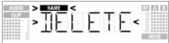
- Press the SETUP control briefly. The display will revert to the Name screen.
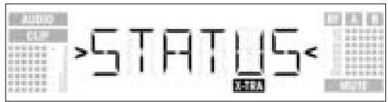
4.3.2 STATUS
The "STATUS" submenu lets you activate a visual warning that alerts you to selectable critical system conditions. If one of the selected conditions occurs, the LED ring around the SETUP control will change from green to red and a warning message will appear on the display that describes the current condition. The warning messages appear in the order of priority:
- "LOW.BAT": Transmitter battery capacity is low.
- "AFCLIP": Audio overload.
- "RF.LOW": Received signal field strength is so low that the receiver audio output has been muted.
- "DIV.Err": Diversity function failed (less than ideal antenna position(s), cable(s)/antenna(s) defective).
The selected warning functions are basically active in LOCK and SETUP modes. In SETUP mode, however, the warning functions will be automatically deactivated while you make adjustments. To delete the warning message from the display, press the SETUP control briefly. This will bring up the next warning message or, if no other critical system conditions were detected, the normal screen. The LED ring will revert to green.
- Call up the EXTRA screen and select "STATUS". The display will change as follows:
- To step through the various warning functions, press the SETUP control briefly.
The name of the first warning function will appear on the display. Depending on which option you last selected, either "ON" or "OFF" will be flashing on the display. To toggle between "ON" and "OFF", turn the SETUP control CW or CCW. - To activate the warning function, select "ON" and press the SETUP control briefly.
- To deactivate the warning function, select "OFF" and press the SETUP control briefly. The next warning function submenu will appear on the display.
Note:
The warning functions will appear in this order:
- "BAT": The batteries inside the transmitter will be dead in about 60 minutes. The related message on the display is "LOW.BAT".
- "AF": The received audio signal drives the receiver into clipping. The related message on the display is "AFCLIP".
- "RF": The field strength of the received RF signal is so low that the receiver audio output is muted to prevent unwanted noise. The related message on the display is "RF LOW".
- "DIV": The same antenna has been active for at least one minute. The related message on the display is "DIV.ErrR".
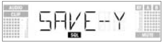
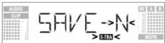
The last warning function is followed by the SAVE submenu.
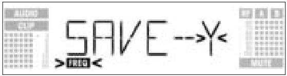
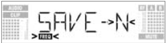
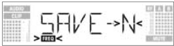
- Press the SETUP control briefly. The display will change as follows:
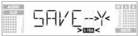
- To save your setting, press the SETUP control briefly. The display will revert to the EXTRA screen.
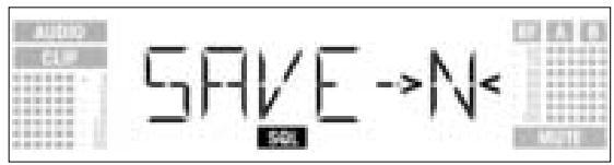
- If you'd rather not save your setting, turn the SETUP control CW or CCW. The display will change as follows:
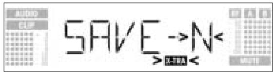
- Press the SETUP control briefly. The display will revert to the EXTRA screen.
The Environment Scan function automatically finds potential interference sources. The factory preset threshold of -85 dB usually provides good results. Should a "jammer" escape the interference detector you can change the threshold.
The selected threshold is also used by the Auto Group Setup and Auto Channel Setup functions.
4.3.3 THRESH
- Call up the EXTRA screen and select "THRESH". The display will change as follows:
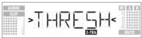
- Press the SETUP control briefly. The display will indicate the current threshold setting for Environment Scan:
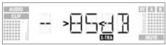
- Turn the SETUP control CW or CCW to set the desired threshold.
- Press the SETUP control briefly. The display will change as follows:
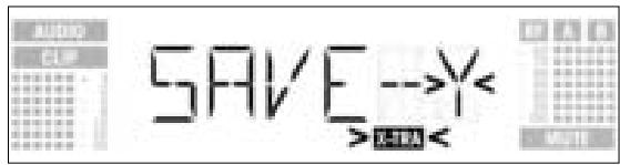
- To save your setting, press the SETUP control briefly. The display will revert to the EXTRA screen.
- If you'd rather not save your setting, turn the SETUP control CW or CCW. The display will change as follows:
- Press the SETUP control briefly. The display will revert to the EXTRA screen.
4.3.4 INFO The INFO submenu lets you call up information about your receiver.
- Call up the EXTRA screen and select "INFO". The display will change as follows:
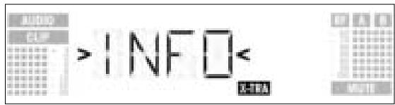
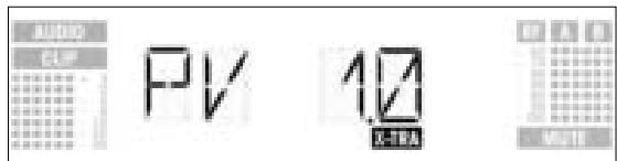
- Press the SETUP control briefly. The display will show the software version:
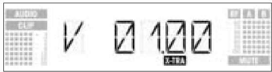
- Turn the SETUP control CW to step through the rest of the information screens in the order shown below:
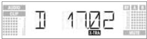
Production date (calender week.year)
Preset version
Exit INFO option
- To step through the above information screens in reverse order, turn the SETUP control CCW.
- To leave the "INFO" submenu, press the SETUP control briefly. The receiver will revert to the EXTRA screen.
To clean the receiver surfaces, use a soft cloth moistened with water.
6 Troubleshooting

| Problem | Possible Cause | Remedy |
| No sound. | 1. AC adapter is not connected to receiver and/or power outlet. 2. Receiver is OFF. 3. Receiver is not connected to mixer or amplifier. 4. Microphone or instrument is not connected to bodypack transmitter. 5. Transmitter is tuned to different frequency than receiver. 6. Transmitter is "OFF" or transmitter MUTE switch at "MUTE". 7. Transmitter batteries are not inserted properly. 8. Transmitter batteries/battery pack dead. 9. Transmitter is too far away from receiver or squelch threshold setting is too high. 10.Obstructions between transmitter and receiver. 11.Receiver is invisible from transmitter location. 12.Receiver too close to metal objects. 13.Transmitter and receiver Preset versions are not identical. | 1. Connect AC adapter to receiver and/or power outlet. 2. Push POWER switch to switch receiver ON. 3. Connect receiver output to mixer or amplifier input. 4. Connect microphone or instrument to audio input on bodypack. 5. Tune transmitter and receiver to the same frequency. 6. Switch transmitter "ON" or set MUTE switch to "ON" position. 7. Insert batteries conforming to "+" and "-" marks. 8. Replace batteries/charge battery pack. 9. Move closer to receiver or choose lower squelch threshold setting. 10.Remove obstructions. 11.Avoid spots where you cannot see receiver. 12.Remove offending objects or move receiv-er away. 13.Verify Preset versions on transmitter and receiver. |
| Noise, crackling, unwanted signals. | 1. Antenna location. 2. Interference from other wireless systems, TV, radio, CB radios, or defective electrical appliances or installations. | 1. Relocate receiver or antennas. 2. Switch off interference sources or defective appliances or tune transmitter and receiver to a different frequency; have electrical installation checked. |
| Distortion. | 1. GAIN control on transmitter is set too high or too low. 2. Interference from other wireless systems, TV, radio, CB radios, or defective electrical appliances or installations. | 1. Decrease or increase GAIN setting just enough to stop the distortion. 2. Switch off interference sources or defective appliances or tune transmitter and receiver to a different frequency; have electrical installation checked. |
| Momentary loss of sound ("dropouts") at some locations within performance area. | • Antenna location. | • Relocate receiver or antennas. If dead spots persist, mark and avoid them. |
| Receiver Error Message | Problem | Remedy |
| ERR.PRG | Microcontroller unable to load any program. | • Contact your AKG Service Center. |
| ERR.-SYS< | Frequency settings cannot be changed. | 1. Switch power to receiver OFF and back ON after about 10 seconds. 2. If problem persists, contact your AKG Service Center. |
| ERR.-USR< | Last setting cannot be loaded. | 1. Set frequency and squelch threshold again. 2. If problem occurs frequently, contact your AKG Service Center. |
| ERR.-FRE< | Frequencies cannot be set from Frequency screen. | 1. Continue with previous setting. 2. Press SETUP control briefly and set frequency from Preset screen. 3. If problem occurs frequently, contact your AKG Service Center. |
| ERR.-PRE< | Error in selected Preset. | 1. Continue with previous Preset. 2. Turn SETUP control CW or CCW to select error-free Preset. 3. If problem occurs frequently, contact your AKG Service Center. |
| ERR.-RF< | PLL error. (Receiver cannot lock on to select-ed frequency.) | 1. Press SETUP control briefly and set differ-ent frequency. 2. If problem persists, contact your AKG Service Center. |
| RF carrier frequency ranges: | 650 to 680, 680 to 710, 720 to 750, 760 to 790, 790 to 820, 835 to 863 MHz |
| Carrier frequencies: | up to 1,200 per range (depending on local conditions) |
| Modulation: | FM |
| Rated deviation: | 20 kHz at 1 kHz (sine wave) |
| Squelch threshold: | adjustable between -70 and -100 dBm |
| Audio bandwidth: | 35 to 20,000 Hz |
| THD at 1 kHz: | <0.3% at rated deviation |
| Signal-to-noise: | 118 dB(A) typical |
| Audio outputs: | - BALANCED 3-pin XLR,adjustable to -30, 0, +6 dB - UNBALANCED TS 1/4" jack |
| Current consumption: | 400 mA typical |
| Power Requirement: | 12 VDC from external power supply |
| Dimensions: | 200 x 44 x 190 mm (7.8 x 1.7 x 7.4 in.) |
| Weight: | 972 g (2.2 lbs.) |
This product complies with the following standards: EN60065:1998, EN301 489-9 v.1.1.1 (09-2000), and EN300 422-2 v.1.1.1 (07-2000).
4.3.3 THRESH (UMBRAL)
3.8 Ajustar o receptor (modo SETUP)
No modo SETUP a trava eletrònica é levantada. O*síbolo "LOCK" está apagado.
- Auto Group Setup
- Auto Channel Setup
- Preset
- Freqência
- Nome do receptor
- Environment Scan
- Nivel squelch
-Rehearsal
-Extra
- IMPORTANT NOTE The SR 4000 and Phantom Power
- To prevent damage to the SR 4000 audio output, please remember the following hints:
- Inhaltsverzeichnis
- FCC Statement
- Safety
- Environment
- Description
- Introduction
- Unpacking
- Optional Accessories
- General Description
- Bottom Panel
- Setting Up
- Setting Up the Receiver (SETUP Mode)
- *Note:
- Selecting Frequency Groups (Auto Group Setup)
- Note:
- Selecting Frequencies from the Frequency Screen
- Editing the Receiver Name Note:
- Edit the current name
- Save or delete the name
- Finding Interference Frequencies
- Setting the Squelch Threshold
- Operating Notes
- Advanced Functions
- NAME
- - Entering a new name
- - Saving or deleting a name
- STATUS
- INFO The INFO submenu lets you call up information about your receiver.
- Troubleshooting
Brand : AKG
Model : SR 4000
Category : Wireless Microphone System