
DMM 4 2 2 - Wireless Microphone System AKG - Free user manual and instructions
Find the device manual for free DMM 4 2 2 AKG in PDF.
| Product Type | 19" Automatic Microphone Mixer for Wireless Microphone System |
| Brand and Model | AKG DMM 4 2 2 |
| Dimensions (W x H x D) | 483 x 44 x 203 mm |
| Weight (with packaging) | 3.5 kg |
| Power Supply | 100-240 V AC, 50-60 Hz, 35 W max |
| Number of Mic/Line Inputs | 4 × balanced XLR (switchable Mic/Line) |
| Number of AUX Inputs | 2 × unbalanced RCA |
| Outputs | 1 × XLR Master, 2 × RCA Record (mono) |
| DSP Functions | Level, treble, bass, low-cut filter, limiter, automix, ducking, NOM-ATT, last mic on, lock |
| Phantom Power | +48 V, 10 mA per input |
| Cascading | Up to 5 units (20 mic inputs max) |
| External Control Connector | Sub-D 26-pin (logic inputs/outputs) |
| Operating Temperature | +5 to +45 °C |
| Operating Humidity | 20% to 83% RH (non-condensing) |
| Package Contents | 1 × DMM 4/2/2, 4 rack mount screws, 4 plastic washers, 1 power supply, 1 quick start guide |
| Maintenance and Cleaning | Disconnect the device, clean with a slightly damp cloth (no solvents or alcohol) |
| Safety | Do not expose to moisture, heat, or shocks; opening only by authorized technical personnel |
| Repairability | Original parts available via AKG after-sales service; repair by certified technician |
| General Information | 24 bit/48 kHz digital mixer; innovative automatic mixing functions (NST, Best Mic On, Noise Detect, LMON) |
Frequently Asked Questions - DMM 4 2 2 AKG
User questions about DMM 4 2 2 AKG
0 question about this device. Answer the ones you know or ask your own.
Ask a new question about this device
Download the instructions for your Wireless Microphone System in PDF format for free! Find your manual DMM 4 2 2 - AKG and take your electronic device back in hand. On this page are published all the documents necessary for the use of your device. DMM 4 2 2 by AKG.
USER MANUAL DMM 4 2 2 AKG
Please read the manual before using the equipement!
MODE D'EMPLOI 50
1 Safety and Environment. 28
Safety 28
Environment 28
2 Description 29
Introduction. 29
Package contents 29
Optional Accessories 29
Brief description 29
Front panel 30
MIC/LINE inputs 30
AUX inputs 30
Operating mode 30
Output 30
Rear panel 31
Input channels. 31
AUX channels 31
Recording output. 31
Output channel 32
Connection for external control 32
Expansion connectors 33
Ground Lift switch 33
Power switch 34
Automatic mixing functions 34
3 Installation and Connection 35
Rack mounting. 35
Daisy-chaining 35
Connecting microphones and auxiliary equipment 35
Connecting external controls 35
Mains connection 36
4 Operation 37
Operating concept 37
Configuring DMM 4/2/2 37
Operating DMM 4/2/2 38
DSP functions 39
LEVEL 39
TREBLE. 40
BASS. 41
LOW CUT. 42
LIMITER 43
AUTOMIXING 44
DUCKING 44
NOM-ATT. 45
LAST MIC ON 45
LOCKED 46
5 Cleaning. 47
6 Specifications 48
General. 48
Power supply unit 48
Inputs 48
Outputs 48
7 Troubleshooting 49
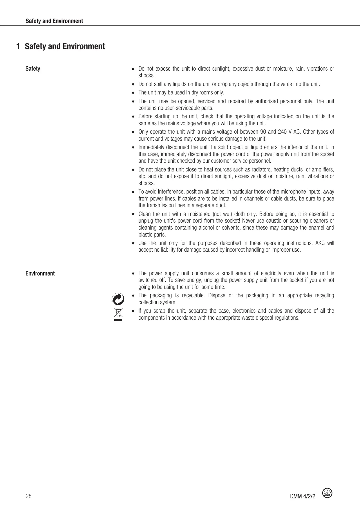
1 Safety and Environment
Safety
- Do not expose the unit to direct sunlight, excessive dust or moisture, rain, vibrations or shocks.
- Do not spill any liquids on the unit or drop any objects through the vents into the unit.
- The unit may be used in dry rooms only.
- The unit may be opened, serviced and repaired by authorised personnel only. The unit contains no user-serviceable parts.
- Before starting up the unit, check that the operating voltage indicated on the unit is the same as the mains voltage where you will be using the unit.
- Only operate the unit with a mains voltage of between 90 and 240V AC. Other types of current and voltages may cause serious damage to the unit!
- Immediately disconnect the unit if a solid object or liquid enters the interior of the unit. In this case, immediately disconnect the power cord of the power supply unit from the socket and have the unit checked by our customer service personnel.
- Do not place the unit close to heat sources such as radiators, heating ducts or amplifiers, etc. and do not expose it to direct sunlight, excessive dust or moisture, rain, vibrations or shocks.
- To avoid interference, position all cables, in particular those of the microphone inputs, away from power lines. If cables are to be installed in channels or cable ducts, be sure to place the transmission lines in a separate duct.
- Clean the unit with a moistened (not wet) cloth only. Before doing so, it is essential to unplug the unit's power cord from the socket! Never use caustic or scouring cleaners or cleaning agents containing alcohol or solvents, since these may damage the enamel and plastic parts.
- Use the unit only for the purposes described in these operating instructions. AKG will accept no liability for damage caused by incorrect handling or improper use.
Environment

- The power supply unit consumes a small amount of electricity even when the unit is switched off. To save energy, unplug the power supply unit from the socket if you are not going to be using the unit for some time.
- The packaging is recyclable. Dispos of the packaging in an appropriate recycling collection system.
- If you scrap the unit, separate the case, electronics and cables and dispose of all the components in accordance with the appropriate waste disposal regulations.
2 Description
Introduction
Thank you for purchasing an AKG product. This Manual contains important instructions for setting up and operating your equipment. Please take a few minutes to read the instructions below carefully before operating the equipment. Please keep the Manual for future reference. Have fun and impress your audience!
Package contents
Please check that the package contains all the parts. Should anything be missing, please contact your AKG dealer.
1xDMM4/2/2
- 4 × screws for rack mounting
- 4 × plastic washers
- 1 x mains plug
- 1 x Quick Setup Guide
Optional Accessories
For optional accessories, refer to the current AKG catalog or folder, or visit www.akg.com. Your dealer will be glad to help.
Brief description
The DMM 4/2/2 is a 19" Automatic Microphone Mixer. The internal signal processing is digital and mono. The inputs and outputs are analogue.
The unit has four balanced inputs, which can be configured as microphone inputs or as line inputs (e.g. for receivers of wireless microphones). These are electrically mono. Furthermore, two unbalanced AUX inputs are also present.
On the output side, the unit has a balanced master output and an unbalanced dual mono recording output.
The inputs and outputs are controlled using the rotary controls and LED rings on the front panel. The unit has a wide-range power supply unit and is connected to the mains using the supplied power cord.
In addition to many DSP functions for signal processing, the DMM 4/2/2 also has innovative automatic mixing functions. These mixing functions may be configured by means of hardware remote control.
If the four balanced inputs are not sufficient for your needs, up to five DMM 4/2/2 can be daisy-chained.
Front panel
The front panel contains a total of eight rotary controls.
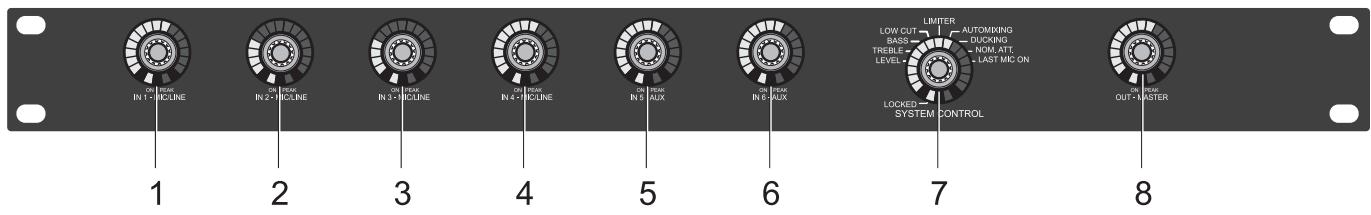
Figure 1: Front panel of the DMM 4/2/2
1 to 4: Microphone or line inputs
5,6: AUX inputs
7: Operating mode
8: Output
The rotary controls can be used to adjust the parameters of the selected audio function.
Each input channel has a green LED "ON" and a red LED "PEAK". "ON" lights up when the input channel is connected. If the Automix function (see "Automatic mixing functions")
Page 34) is switched off, "ON" lights continuously. "PEAK" lights up when the signal on an input channel is close to the maximum control limit. In this case, the level should be turned down or the input sensitivity should be changed.

NOTE
The input sensitivity is adjusted using the DIP switches (see "Input channels" Page 31) on the rear panel of the connected unit.

NOTE
MUTE function:
Briefly pressing a rotary control causes the corresponding channel to be muted. The MUTE function is indicated by the steady flashing of the LED ring. Another brief press of the rotary control removes the MUTE function.
VU function:
The "SYSTEM CONTROL" rotary control can be used to display the current audio level of the inputs and outputs, see Operating DMM 4/2/2 (Page 38).
MIC/LINE inputs
The DMM 4/2/2 has four balanced input channels for connecting low-impedance dynamic or condenser microphones and other audio sources, e.g. receivers for wireless microphones. A rotary control is available for each input channel. These are labelled "IN 1 - MIC/LINE" to "IN 4 - MIC/LINE".
AUX inputs
The DMM 4/2/2 has two AUX inputs for connecting external audio sources, e.g. a CD player. A rotary control is available for each input channel. These are labelled "IN 5 - AUX" and "IN 6 - AUX".
Operating mode
The DMM 4/2/2 has a large number of functions (see "DSP functions" Page 39), such as volume, treble ranges, bass, auto-mix functions, etc. The "LOCKED" function can be used to lock the entire unit. These functions can be selected using the "SYSTEM CONTROL" rotary control.
Output
The rotary control for the master output channel is labelled "OUT MASTER". This rotary control is used to adjust the volume, treble, bass, limiting behaviour and attenuation on the output channel.
Rear panel
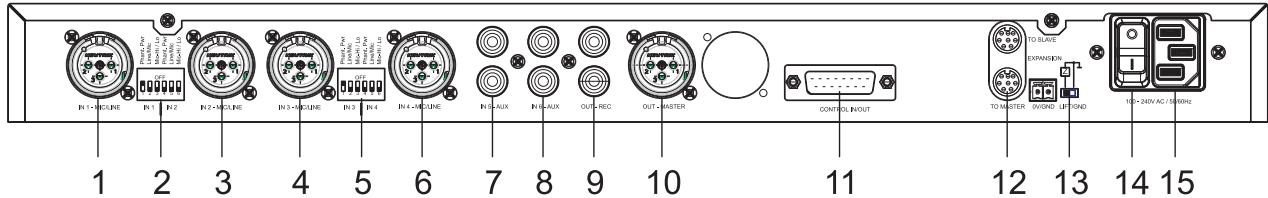
Figure 2: Rear panel of the DMM 4/2/2
1,3,4,6: Input channels
2,5: DIP switches
7,8: AUX channels
9: Recording output
10: Output channel
11: Connection for external control
12: Expansion connectors
13: Ground Lift switch
14: Power switch
15: Mains connection
Input channels
The four balanced input channels can be accessed via 3-pin XLR sockets. These are labelled "IN 1 - MIC/LINE" to "IN 4 - MIC/LINE". The input levels can be adjusted using the rotary controls "IN 1 - MIC/LINE" to "IN 4 - MIC/LINE" on the front panel.
Between two XLR sockets there are 6-way DIP switches. This can be used to configure two input channels in each case.
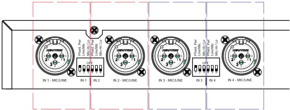
Figure 3: DIP switches for the input channels
"Phantom Pwr" - switch phantom power on/off on both audio wires of the selected channel.
"Line/Mic" - switch preamp from microphone to line input. In that case the gain is 0 dB.
"Mic-Hi/Lo" - switch gain from +60 dB to +40 dB.
AUX channels
The two auxiliary input channels can be accessed via two RCA jacks. The RCA jacks are labelled "IN 5 - AUX" and "IN 6 - AUX". The input levels can be adjusted with the rotary controls "IN 5 - AUX" and "IN 6 - AUX" on the front panel.
Recording output
Two RCA jacks, labelled "OUT REC", are available for connecting recording equipment. A mono signal is present at each of the two jacks.
Output channel
The master output channel is in the form of a male XLR connector and is labelled "OUT - MASTER". The output level can be adjusted with the "OUT MASTER" rotary control on the front panel.
Connection for external control
The Control In/Out jack is a 26-pin D-sub high density connector. This jack is used for connecting external units, such as keys of microphone stations, microphone LED rings or camera control systems.
The following table shows the pin assignments of the D-sub high density jack:
| 01: FORCE ON 1 | 08: GND | 15: +3V3 | 22: LOGIC OUT 4 |
| 02: FORCE ON 2 | 09: GND | 16: +5V | 23: +3V3 |
| 03: FORCE ON 3 | 10: FORCE OFF 1 | 17: +12V | 24: +5V |
| 04: FORCE ON 4 | 11: FORCE OFF 2 | 18: GND | 25: -12V |
| 05: VCA IN | 12: FORCE OFF 3 | 19: LOGIC OUT 1 | 26: +48V |
| 06: GND | 13: FORCE OFF 4 | 20: LOGIC OUT 2 | |
| 07: GND | 14: GND | 21: LOGIC OUT 3 |
FORCE ON/Override
With a HI level at the FORCE ON input, a channel is manually forced to switch on.
- Overrides a disconnection by the automatic mixing functions
- Overriding of DUCKING function (see "DUCKING" Page 44)! Channel is not attenuated by 10 dB
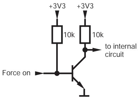
Figure 4: FORCE ON diagram

NOTE
A channel activated by Force On has no effect on the automix algorithm (see "Automatic mixing functions" Page 34) Noise Detect, NST and Best Mic On.
FORCE OFF
With a HI level at the FORCE OFF input, a channel is manually forced to switch off. This input has the highest priority:
- Overrides FORCE ON
- Overrides the activation of a channel by the automatic mixing functions
- Overrides the holding of a channel by Last Mic On (see "Automatic mixing functions" Page 34)
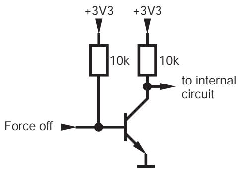
Figure 5: FORCE OFF diagram

NOTE
A channel switched off by Force Off has no effect on the automix algorithm (see "Automatic mixing functions" Page 34) Noise Detect, NST and Best Mic On.
VCA IN
With a DC signal, the overall volume can be varied. This jack allows you to externally adjust or mute the output level. Depending on the application, you can use potentiometers, switches or external control voltages for this.
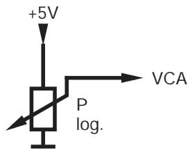
Figure 6: VCA IN diagram

NOTE
If you are using an external potentiometer, the maximum adjustable volume will be determined by the "OUT MASTER" rotary control. For the correct adjustment, the potentiometer must be set to 100% . Thereafter, the maximum adjustable volume is limited on the "OUT MASTER" rotary control. The potentiometer can now be used to adjust the volume below the set maximum value. This procedure prevents unwanted feedback.
LOGIC OUT
As soon as the microphone associated with the channel is activated, this output is set to 5V . It can then be used, for example, to trigger a camera control or activate the LED ring of a microphone.
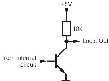
Figure 7: LOGIC OUT diagram
Expansion connectors
If four microphone channels are not sufficient, several DMM 4/2/2 can be connected together (up to a maximum of 5). The expansion connectors TO MASTER and TO SLAVE can be used for daisy-chaining. These are two 8-pin mini-DIN jacks labelled "EXPANSION".
Ground Lift switch
The Ground Lift switch connects or isolates the case with 0V potential of the power supply.
Automatic mixing functions
Power switch
The power switch is used to turn on the unit.
The innovative automatic mixing functions of the DMM 4/2/2 assess whether a channel is switched on and adjust the level of the output signal.
The automix algorithm is composed of the following functions, among others:
- NST (Noise Sensitive Threshold)
The threshold that must be exceeded in order to activate a microphone adapts automatically to the ambient noise level. In other words, the louder the environment, the louder you will need to speak into a microphone in order to activate it. This prevents microphones from activating when they are not required.
Best Mic On
Comb filter effects may arise when two microphones are positioned close to each other. To suppress these unnaturally muffled or hollow signals, only the microphone channel with the highest level is switched on.
- Noise Detect
Continuous interfering signals such as noise from fans or air-conditioning units are recognised and not used as activation criteria for microphone channels.
- LMON (Last Mic On)
The most recently switched on input signal is maintained until the next channel is activated.
NOM Attenuation (Number of Open Microphones Attenuation)
On account of the risk of feedback from multiple open microphone channels, the master output signal is attenuated by an adjustable factor for each activated channel.
3 Installation and Connection
Rack mounting
Daisy-chaining
Install the DMM 4/2/2 in your 19" rack using the supplied screws and washers.
If you need more than four microphone channels, you can daisy-chain several DMM 4/2/2.
Using the expansion connectors on the rear panel, up to five units of the same type can be daisy-chained and operated as a single unit. This gives you up to 20 balanced input channels and 10 AUX input channels. The master output and the recording output are only available on the master unit.
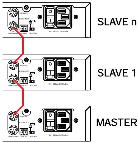
Figure 8: daisy-chaining multiple units
All units independently detect whether they are master or slave units, according to the following principle: if a unit is not connected to any other unit by means of its "TO MASTER" jack, it is the last link in the chain of units. It therefore recognises that it should act as the master unit.

ATTENTION
The expansion cable must not exceed 20 cm in length. We recommend original AKG accessories.
Connecting microphones and auxiliary equipment

NOTE
Read through the operating instructions of your microphones and auxiliary equipment before connecting them.
Connect the microphones and auxiliary equipment to the rear panel of the DMM 4/2/2:
1) Connect the microphones and other audio sources (e.g. receivers for wireless microphones) to the "MIC/LINE" input channels.
2) Connect your auxiliary equipment (CD player etc.) to the "AUX" inputs using the RCA cables.
3) Connect the output channel "OUT - MASTER" to a mixing console or amplifier.
4) Connect the RCA jacks of the recording output "OUT - REC" to a recording device.
Connecting external controls
Connect the hardware (that you want to remotely control using the DMM 4/2/2) to the DMM 4/2/2 via the 26-pin D-sub "CONTROL IN/OUT" high density jack.
Mains connection

Do not connect the unit to the mains power supply until you have made all the audio connections!
1) Connect the power supply unit cable to the appropriate socket on the rear panel of the DMM 4/2/2.
2) Plug the power supply unit into a mains socket.
4 Operation
Operating concept
The DMM 4/2/2 has a single master bus, to which the input channels are mixed and picked up at the output channels. The unit is therefore mono in its internal structure.
Some of the individual input and output channels have configuration options which are set via DIP switches. Other settings for the input and output channels are adjusted using the rotary controls. The function to be changed is set using the "SYSTEM CONTROL" rotary control. If a function selected in this way can be changed on an input or output channel, at least one LED will light up on its LED ring.
Furthermore, the "SYSTEM CONTROL" rotary control can be used to display the audio level on the inputs and outputs, see Operating DMM 4/2/2 (Page 38).
The default position of the "SYSTEM CONTROL" rotary control is the "LEVEL" setting. If this control is set to another property, and no settings are carried out on any of the rotary controls for more than 30 seconds, the "SYSTEM CONTROL" rotary control automatically returns to the "LEVEL" position.
Configuring DMM 4/2/2

NOTE
Please read the instructions for connecting your microphones and auxiliary equipment under Installation and Connection (Page 35).
Configure the connected microphones and auxiliary equipment using the DIP switches on the rear panel of the DMM 4/2/2:
1) If you use condenser microphones, check what supply voltage or what type of power supply they require. If your condenser microphones are suitable for phantom power, switch on the phantom power. To do so, set the "Phantom Pwr" DIP switch to "ON".

ATTENTION
If you are using wireless microphones, it is essential to switch off the phantom power on those inputs to which you have connected a receiver, in order to avoid damaging the receiver.
2) Use the "Line/Mic" DIP switch to set the preamp to "Mic" if you are using a microphone, and to "Line" if you are using other connected audio sources, such as receivers for wireless microphones.
3) For the gain of the input signals, choose between +40 dB and +60 dB. To do so, set the DIP switch to "Mic-Lo" or "Mic-Hi".

NOTE
The setting "Mic-Hi" results in a greater gain of the input signals. This setting is suitable for microphones with a low output level.
For microphones with a high output level the "Mic-Lo" setting is recommended.
4) Turn the unit on with the power switch.
Operating DMM 4/2/2
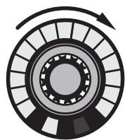
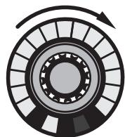
To operate the rotary controls on the front panel of the DMM 4/2/2:
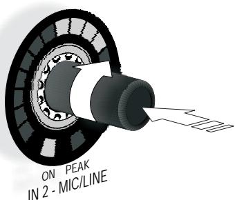
Figure 9: Operation of the rotary control
Turn the rotary control clockwise or counter-clockwise to make changes to inputs and outputs and function settings (see "DSP functions" Page 39). These changes are shown on the LED ring around the rotary control. The starting point and the increments on the LED ring will vary according to function.
Audio level display:

NOTE
If the LEVEL (Page 39) function is selected, the set level is displayed on the LED rings of the inputs and outputs.
Briefly pressing the "SYSTEM CONTROL" rotary control switches the display on the LED rings to VU meter, the display of the actual audio level present. As long as the VU meter mode is activated, the LEVEL LED flashes on the "SYSTEM CONTROL" rotary control. Pressing the "SYSTEM CONTROL" rotary control again deactivates the VU meter mode.
Adjust the properties of an input or output signal with the available functions (see "DSP functions" Page 39):
1) Select the desired function on the "SYSTEM CONTROL" rotary control. Turn the rotary control until the LED next to the desired function lights up.
2) Use the rotary controls to adjust the input channels with the selected function.
3) Use the "OUT MASTER" rotary control to adjust the output channel with the selected function.
The recording output has no settings.

NOTE
Ten seconds after the last change, the "SYSTEM CONTROL" rotary control goes back to the "LEVEL" function.
DSP functions
The following signal processing functions are available for the input channels and the output channel on the "SYSTEM CONTROL" rotary control:
LEVEL
In LEVEL mode the following channels can be changed in volume:
- all MIC/LINE input channels
- all AUX input channels
- master output
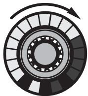
With a clockwise rotation, the adjustment range extends from - to +12 dB (0 dBFS). The adjustment takes place in the appropriate increments.
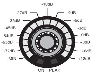
Figure 10: Division of the LED ring for the LEVEL function
At - one LED lights up, at +12 dB (0 dBFS) the entire LED ring lights up.

ON PEAK IN 2-MIC/LINE

IN 2 - MIC/LINE
IN 2 - MIC/LINE
Figure 11: Adjustment range for the LEVEL function

NOTE
MUTE function:
Briefly pressing a rotary control causes the corresponding channel to be muted. The MUTE function is indicated by the steady flashing of the LED ring. Another brief press of the rotary control removes the MUTE function.
VU function:
The "SYSTEM CONTROL" rotary control can be used to display the current audio level of the inputs and outputs, see Operating DMM 4/2/2 (Page 38).
TREBLE
In TREBLE mode the treble range of the following channels can be adjusted:
- all MIC/LINE input channels
- all AUX input channels
- master output
The filter is designed as a second order treble shelving filter. The cut-off frequency is 10kHz . With a clockwise rotation, the adjustment range extends from -14 dB to +14 dB in increments of 2 dB.
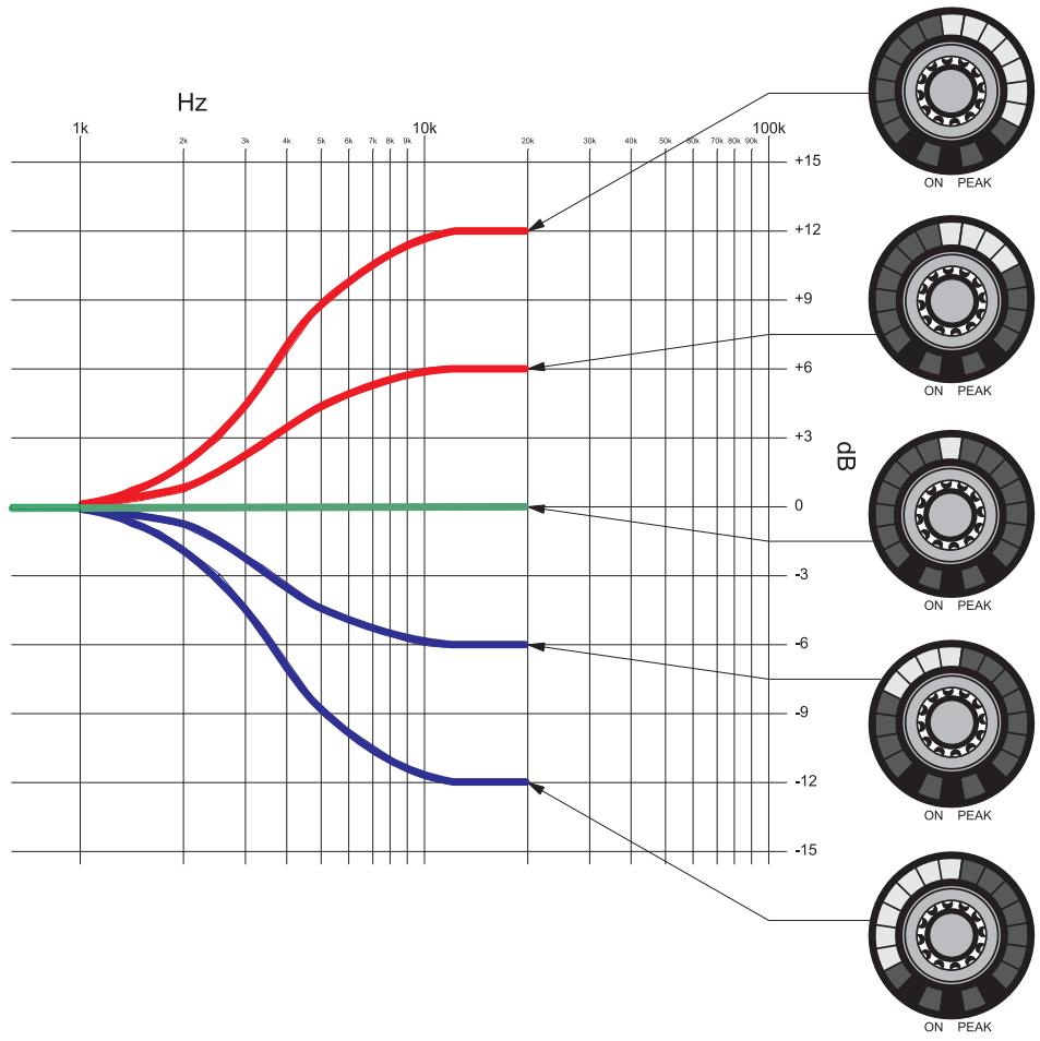
Figure 12: Adjustment range for the TREBLE function
With linear adjustment, only the upper middle LED lights up. This LED (0 db) is also considered to be the starting point for a clockwise or counter-clockwise rotation.
BASS
In BASS mode the bass range of the following channels can be adjusted:
- all MIC/LINE input channels
- all AUX input channels
- master output
The filter is designed as a second order bass shelving filter. The cut-off frequency is 100Hz . With a clockwise rotation, the adjustment range extends from -14dB to +14dB in increments of 2dB .
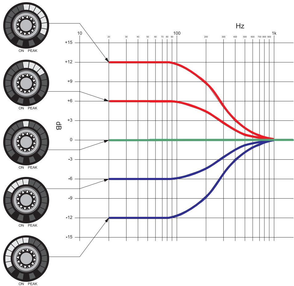
Figure 13: Adjustment range for the BASS function
With linear adjustment, only the upper middle LED lights up. This LED (0 db) is also considered to be the starting point for a clockwise or counter-clockwise rotation.
LOW CUT
In LOW CUT mode the bass range of the following channels can be adjusted:
- all MIC/LINE input channels
- all AUX input channels
The filter is designed as a second order bass cut filter. With a clockwise rotation, the cut-off frequency adjustment range extends from 0Hz (no bass cut) to 140Hz (severe attenuation). At 140Hz the entire LED ring lights up, at 0Hz one LED is illuminated.
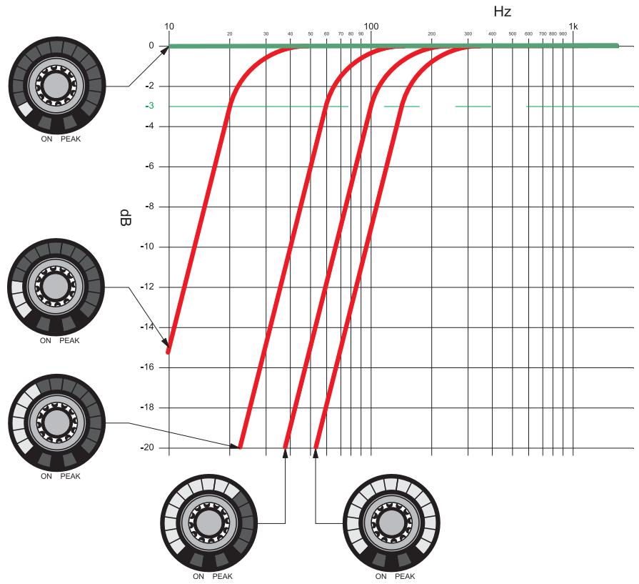
Figure 14: Adjustment range for the LOW CUT function
LIMITER
In LIMITER mode the limiting behaviour of the master output is changed.
Turning the "OUT MASTER" rotary control clockwise increases the threshold of the limiter. Turning it counter-clockwise decreases the threshold.
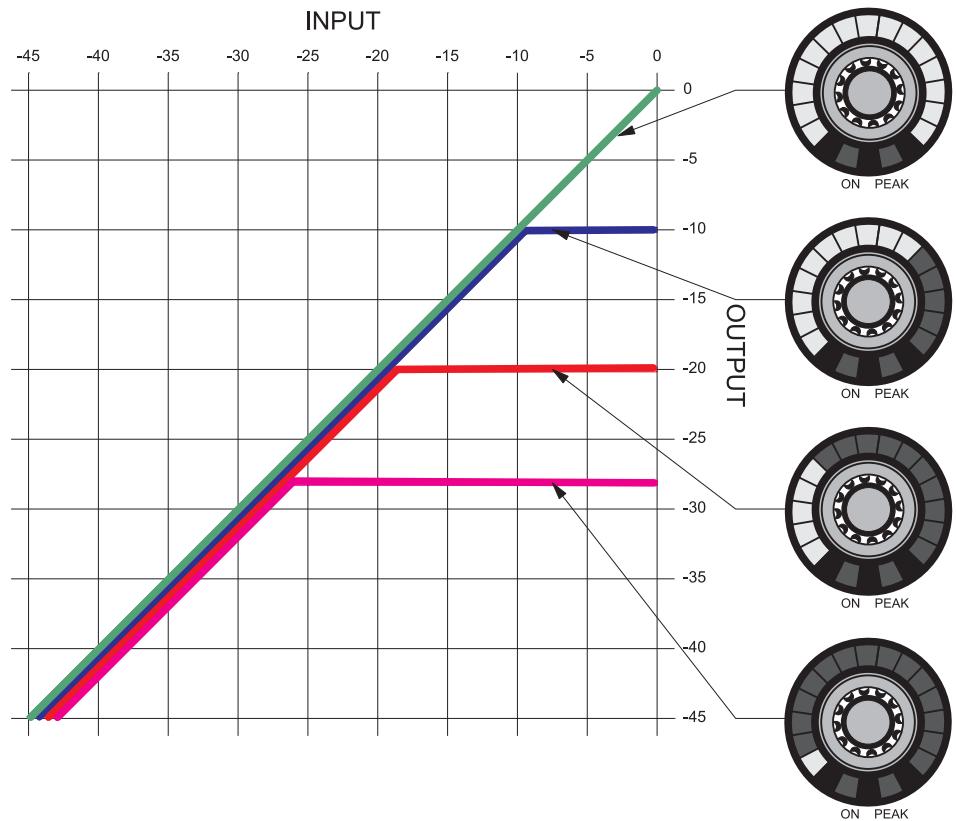
Figure 15: Adjustment range for the LIMITER function
A low threshold setting (in this case: -28 dBFS and one illuminated LED) results in a very powerful limitation, while the output level remains relatively small. A higher threshold setting (in this case: 0 dBFS and a fully illuminated LED ring) means there is no limitation.
AUTOMIXING
In AUTOMIXING mode the automatic mixing functions (Page 34) can be switched on or off for the input channels.
Turning the control clockwise switches the function on, and the LED ring lights up completely.
Turning the control counter-clockwise switches the function off, and only one LED lights up.

ON PEAK
ON PEAK
Figure 16: LED ring when switching a function off/on

NOTE
Pressing the rotary control also switches the function on or off.
DUCKING
In DUCKING mode it is determined which MIC/LINE or AUX input channel can attenuate the other channels by 10 dB when it is active. This mode works independently of the enabled or disabled automatic mixing functions.

NOTE
This function can only be active on a single input channel. Enabling the DUCKING function on another input channel causes the function to be disabled on the previous channel.
Turning the control clockwise switches the function on, and the LED ring lights up completely.
Turning the control counter-clockwise switches the function off, and only one LED lights up.

ON PEAK
ON PEAK
Figure 17: LED ring when switching a function off/on

NOTE
Pressing the rotary control also switches the function on or off.
NOM-ATT.
In NOM ATTENUATION mode the "OUT MASTER" rotary control is used to set the attenuation by which the master signal is attenuated per connected input channel.
NOM ATTENUATION only works for channels that are set to AUTOMIXING mode!

NOTE
With manual operation, NOM ATTENUATION would not make sense, since in this case all the channels are connected and therefore a constant attenuation would be present. The automatic mixing functions and the logic functions Force On and Force Off can affect this mode!
With a clockwise rotation, the adjustment range extends from 0 dB to 3 dB, in increments of 1 dB. The adjustment takes place in the appropriate increments.

Figure 18: Division of the LED ring of the NOM-ATT function
LAST MIC ON
In LAST MIC ON mode you can set whether the most recently active microphone channel remains open.
The function is set by turning the "OUT MASTER" rotary control. Turning the control clockwise switches the function on, and the LED ring lights up completely. Turning the control counterclockwise switches the function off, and only one LED lights up.
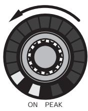
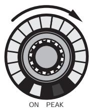
Figure 19: LED ring when switching a function off/on

NOTE
Pressing the rotary control also switches the function on or off.
LOCKED
In LOCKED mode the rotary controls or the entire unit are protected against improper use by means of locking.
Locking the "SYSTEM CONTROL" rotary control
The "SYSTEM CONTROL" rotary control is locked by pressing it (for longer than 2 seconds). The "LOCKED" and "LEVEL" LEDs will light up. Turning the rotary control allows you to review all the channel settings, but only the setting of the input and output levels can be changed. All other functions are locked against input. Briefly pressing the control in LEVEL mode allows the display to be toggled between VU meter and setting mode.
Pressing the "SYSTEM CONTROL" rotary control for longer than 1.5 seconds removes the locking. The rotary control will be positioned in the default setting "LEVEL".
Locking the entire unit
The entire unit can be completely locked by simultaneously pressing the "SYSTEM CONTROL" and "OUT MASTER" rotary controls (for longer than 2 seconds). The original settings will be saved. The "LOCKED" and "LEVEL" LEDs will light up. Turning the rotary control only allows you to review all the channel settings. All functions are locked against input. Briefly pressing the control in LEVEL mode allows the display to be toggled between VU meter and setting mode.
Pressing the "SYSTEM CONTROL" and "OUT MASTER" rotary controls for longer than 1.5 seconds removes the locking. The "SYSTEM CONTROL" rotary control will be positioned in the default setting "LEVEL".
Exempting individual channels from the locking
If the entire unit has been locked, as described above, individual input channels and the "OUT MASTER" channel can be exempted from the locking. The excluded channels can then only be adjusted in volume. Pressing the rotary control of the desired channel (for more than 2 seconds) excludes the channel from the locking. Pressing the control again (for longer than 1.5 seconds) relocks the channel.

NOTE
The set LOCK states are retained even after switching the DMM 4/2/2 off and on again!
5 Cleaning
Unplug the power supply unit from the socket.
Clean the surface of the unit with a moistened (not wet) cloth.

ATTENTION
Never use caustic or scouring cleaners or cleaning agents containing alcohol or solvents, since these may damage the enamel and plastic parts.
6 Specifications
General
| Dimensions of unit W x H x D | 483 x 44 x 203 mm |
| Weight of unit (with packaging) | 3.5 kg |
| Permissible ambient temperature in operation | + 5 ... + 45°C |
| Minimum humidity in operation | 20 % |
| Maximum humidity in operation (non-condensing) | 83 % |
Power supply unit
| Input voltage: | 100 ... 240 V AC |
| Mains frequency: | 50 ... 60 Hz |
| Power consumption max.: | 35 W |
| Output voltages: | +5 V DC / +12 V DC / -12 V DC |
The 3.3 V DC supply voltages for microcontrollers and FPGA are generated internally from the available +5V by means of an additional DC/DC converter. The supply voltage for the phantom power of +48V is generated from the available +5V with an additional DC/DC converter.
Inputs
Balanced inputs - preamp
| Line / Mic Lo / Mic Hi | 0 dB / +40 dB / +60 dB |
| Input level max.: | +15 dBu |
| Common-mode rejection: | >70 dB |
| Dynamic: | >90 dB |
| Input impedance: | >8 kOhm |
| Balanced inputs - phantom power | |
| Phantom power: | +48 V DC |
| Supply current per input max.: | 10 mA |
| Feed resistances: | 2 x 6.8 kOhm |
| Balanced and AUX inputs - Analogue Digital Converter | |
| Data format: | 24 bit |
| Sample frequency: | 48 kHz |
| AUX inputs - preamp | |
| Input level max.: | +15 dBu |
| Dynamic: | >90 dB |
| Input impedance: | >15 kOhm |
Outputs
Recording and master output
| Output level max.: | +10 dBu |
| Dynamic: | >90 dB |
| Load impedance min.: | <100 Ohm |
| Digital analogue conversion for recording and master output | |
| Data format: | 24 bit |
| Sample frequency: | 48 kHz |
This product conforms to the standards listed in the Declaration of Conformity. To order a free copy of the Declaration of Conformity, visit http://www.akg.com or contact sales@akg.com.
7 Troubleshooting

DANGER OF INJURY! The unit may be opened for troubleshooting by authorised personnel only!
| Problem | Possible cause | Remedy |
| No sound | Power supply unit is not connected to unit | Connect power supply unit to unit |
| Power switch off | Turn power switch to on position | |
| Unit is not connected to amplifier | Connect output channel to amplifier | |
| Microphone or auxiliary equipment not connected to unit | Connect microphone or auxiliary equipment to unit | |
| Volume controls set to minimum | Turn up volume control | |
| Volume controls set to mute | Cancel muting by pressing rotary control | |
| Pre-amplification not set correctly | Set DIP switch on rear panel to correct pre-amplification | |
| Phantom power switched off | Switch on phantom power for condenser microphones | |
| External potentiometer set to minimum | Turn up external potentiometer | |
| No sound with sinusoidal feed | Automix algorithm suppressing constant signal | Exclude channel from automix algorithm |
| Distorted signal reproduction | Pre-amplification not set correctly | Set DIP switch on rear panel to correct pre-amplification |
| Volume controls turned up too far | Turn down volume | |
| Level of input signal too high | Attenuate input signal | |
| Microphone channel does not automatically switch itself off | LMON function enabled | Disable LMON function |
| FORCE ON active on this channel | Deactivate FORCE ON | |
| Microphone channel does not automatically switch itself on | FORCE OFF active on this channel | Deactivate FORCE OFF |
If, in spite of these instructions, the error persists, the DMM 4/2/2 should be sent to AKG GmbH for checking!
Sommaire
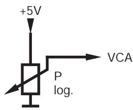
Figure 6: Diagramme VCA IN

REMARQUE
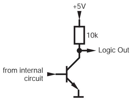
Figure 7: Diagramme LOGIC OUT
Interruptor Ground Lift 82
Interruptorderead 82
Interruptor Ground Lift
For other products and distributors worldwide visit www.akg.com or www.harman.com


ROHS OK
H A Harman International Company
Technische Änderungen vorbehalten. Specifications subject to change without notice. Ces caractéristiques sont susceptibles de modifications. Nos reservamos el derecho de introducir modificacionesétécnicas.
Printed in Austria on recycled paper
09/09/9100 U 13140

- Safety and Environment
- Safety
- Environment
- Description
- Introduction
- Package contents
- Optional Accessories
- Brief description
- Front panel
- MUTE function:
- VU function:
- MIC/LINE inputs
- AUX inputs
- Operating mode
- Output
- Rear panel
- Input channels
- AUX channels
- Recording output
- Output channel
- Connection for external control
- FORCE ON/Override
- FORCE OFF
- VCA IN
- LOGIC OUT
- Expansion connectors
- Ground Lift switch
- Automatic mixing functions
- Power switch
- Installation and Connection
- Mains connection
- Operation
- Operating concept
- Configuring DMM 4/2/2
- Operating DMM 4/2/2
- Audio level display:
- DSP functions
- LEVEL
- TREBLE
- BASS
- LOW CUT
- LIMITER
- AUTOMIXING
- DUCKING
- NOM-ATT.
- LAST MIC ON
- LOCKED
- Locking the "SYSTEM CONTROL" rotary control
- Locking the entire unit
- Exempting individual channels from the locking
- Cleaning
- Specifications
- General
- Power supply unit
- Inputs
- Balanced inputs - preamp
- Outputs
- Recording and master output
- Troubleshooting
- Sommaire
- Interruptor Ground Lift
Brand : AKG
Model : DMM 4 2 2
Category : Wireless Microphone System