
WMS 80 - Wireless Microphone System AKG - Free user manual and instructions
Find the device manual for free WMS 80 AKG in PDF.
| Product type | Wireless microphone system |
| Brand | AKG |
| Model | WMS 80 |
| Available frequency ranges | 710.2 - 860.9 MHz (depending on version) |
| Modulation | FM |
| Audio bandwidth | 50 - 20,000 Hz |
| Signal-to-noise ratio (receiver) | >100 dB(A) |
| Distortion (handheld transmitter) | <0.5% |
| RF output power | 10 mW |
| Receiver power supply | 120/230 V AC, 50/60 Hz |
| Transmitter power supply | 2 x 1.5 V AA batteries |
| Transmitter battery life | >8 hours |
| Receiver dimensions (W x D x H) | 210 x 170 x 42 mm |
| Handheld transmitter dimensions (L x Ø) | 240 x 36 mm |
| Bodypack transmitter dimensions (L x W x H) | 92 x 65 x 20 mm |
| Receiver weight | 470 g |
| Handheld transmitter weight | 245 g |
| Bodypack transmitter weight | 76 g |
| Main functions | True Diversity, adjustable squelch, channel selector, balanced and unbalanced audio outputs, compander, limiter |
| Maintenance and cleaning | Clean with a soft cloth moistened with denatured alcohol |
| Safety instructions | Do not expose to moisture, heat or shocks; respect battery polarity |
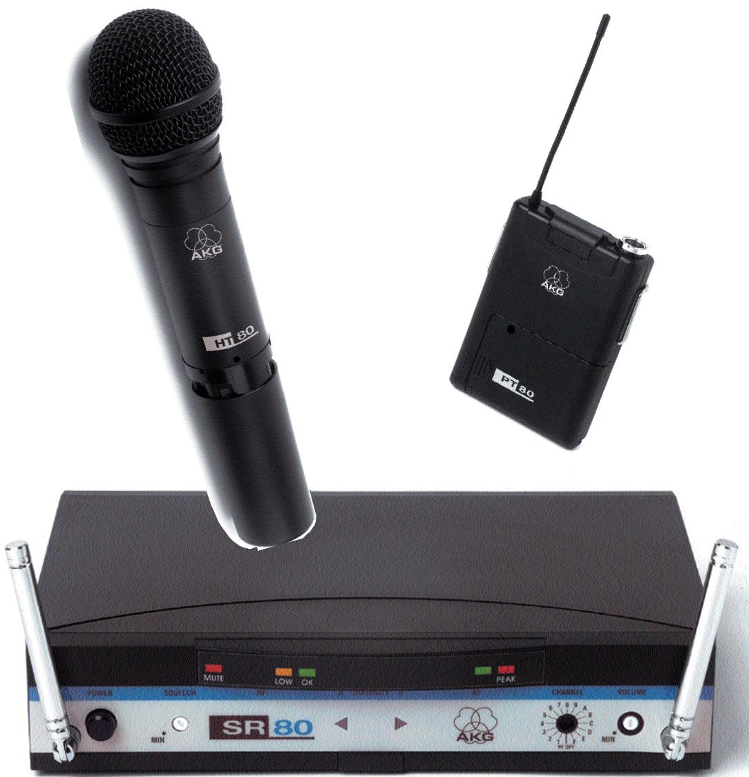
| Supplied accessories | SR 80 receiver, HT 80 or PT 80 transmitter, power supply unit, rack mount kit, screwdriver, batteries, etc. |
Frequently Asked Questions - WMS 80 AKG
User questions about WMS 80 AKG
0 question about this device. Answer the ones you know or ask your own.
Ask a new question about this device
Download the instructions for your Wireless Microphone System in PDF format for free! Find your manual WMS 80 - AKG and take your electronic device back in hand. On this page are published all the documents necessary for the use of your device. WMS 80 by AKG.
USER MANUAL WMS 80 AKG
Wireless Microphone Systems

Bedienungsanleitung
Seite
Wireless Microphone System

SR 80

HT 80


WMS 80
Wireless Microphone Systems

User Instructions
Contents
Page
FCC Statement 3
- Introduction 3
- Precautions 3
- The WMS 80 Systems 3
3.1. Handheld System 3
3.2. Bodypack System 3
3.3. Optional Accessories 3
- SR 80 Receiver 3
4.1. Controls 3
4.1.1. Front Panel. 3
4.1.2.Rear Panel. 4
4.2. Optional Accessories. 4
- HT 80 Handheld Transmitter 4
5.1. Controls 4
5.2. Interchangeable Microphone Elements 4
5.3. Optional Accessories. 4
- PT 80 Bodypack Transmitter 4
6.1. Controls 4
6.2.Microphones,Guitar Cable. 5
6.3. Optional Accessories. 5
- Frequencies 5
7.1. Frequency Sets. 5
7.2. Ordering Replacement Transmitters and/or Receivers. 5
- Multichannel Systems 5
- Setting Up 5
9.1. Selecting Carrier Frequencies 5
9.1.1.Multichannel Systems 5
9.1.2. Changing Carrier Frequencies 5
9.2. HT 80 Handheld Transmitter 6
9.2.1.Microphone Element 6
9.2.2. Inserting, Testing, and Removing Batteries 6
9.3. PT 80 Bodypack Transmitter 6
9.4. SR 80 Receiver 6
9.4.1.Placement 6
9.4.2.Rack Mounting 6
9.4.3. Audio connection 6
9.4.4. Connecting to Power 7
9.4.5.Antennas. 7
9.5. System Adjustments 7
9.5.1.Multichannel Systems 7
9.6. Important Hints for Reliable Operation 7
- Cleaning 7
- Specifications 8
- Frequency List 9
FCC Statement
This equipment has been tested and found to comply with the limits for a Class B digital device, pursuant to Parts 74, 15, and 90 of the FCC Rules. These limits are designed to provide reasonable protection against harmful interference in a residential installation. This equipment generates, uses, and can radiate radio frequency energy and, if not installed and used in accordance with the instructions, may cause harmful interference to radio communications. However, there is no guarantee that interference will not occur in a particular installation. If this equipment does cause harmful interference to radio or television reception, which can be determined by turning the equipment off and on, the user is encouraged to try to correct the interference by one or more of the following measures:
- Reorient or relocate the receiving antenna.
- Increase the separation between the equipment and the receiver.
- Connect the equipment into an outlet on a circuit different from that to which the receiver is connected.
- Consult the dealer or an experienced radio/TV technician for help.
Shielded cables and I/O cords must be used for this equipment to comply with the relevant FCC regulations. Changes or modifications not expressly approved in writing by AKG Acoustics may void the user's authority to operate this equipment.
This device complies with Part 15 of the FCC Rules. Operation is subject to the following two conditions: (1) this device may not cause harmful interference, and (2) this device must accept any interference received, including interference that may cause undesired operation.
1. Introduction
Thank you for selecting the WMS 80 wireless microphone system from AKG. Please take the time to read through this Manual. It contains information on how to make optimum use of your equipment. Have fun!
2. Precautions
2.1. Spill no liquids on the equipment and do not drop any objects through the ventilation slots in the equipment.
2.2. Do not place the equipment near heat sources such as radiators, heating ducts, or amplifiers, etc. and do not expose it to direct sunlight, excessive dust, moisture, rain, mechanical vibrations, or shock.
2.3.Be sure to dispose of used batteries as required by local waste disposal rules. Never throw batteries into a fire (risk of explosion).
3. The WMS 80 Systems
Two different WMS 80 Systems are available:
3.1. Handheld System
1 SR 80 Receiver
1 AC power adapter for 11.7 VAC
1 RMU 80 19" rack mounting kit for 2 SR 80 receivers
1 BP 80 blank panel
1 screwdriver
1 HT 80 Handheld Transmitter
2 AA size 1.5 V dry batteries
1 SA 43 stand adapter
1 adjustable protective ring for controls
3.2. Bodypack System
1 SR 80 Receiver
1 AC power adapter for 11.7 VAC
1 RMU 80 19" rack mounting kit for 2 SR 80 receivers
1 BP 80 blank panel
1 screwdriver
1 PT 80 Bodypack Transmitter
1 belt clip
2 AA size 1.5 V dry batteries
Check that the package contains all the parts listed above for your system. If anything is missing, please contact your AKG dealer.
3.3. Optional Accessories
CH 60/80 plastic carrying case for one complete WMS 80 system.
Color Coding Kit: Set of rings (for the HT 80) and platelets (for SR 80 and PT 80) in various colors for identifying the individual channels of a multichannel system.
4. SR 80 Receiver
The SR 80 is a stationary True Microcontrolled Diversity receiver for use with WMS 80 transmitters. The SR 80 operates in a subband up to 4MHz wide of the 710MHz to 861MHz UHF carrier frequency range. The SR 80 can be switched to a maximum of 15 different carrier frequencies depending on local frequency allocations.
4.1. Controls
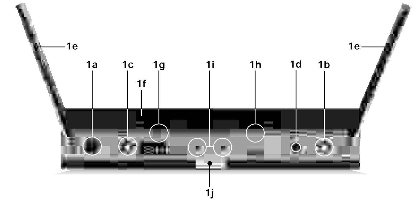
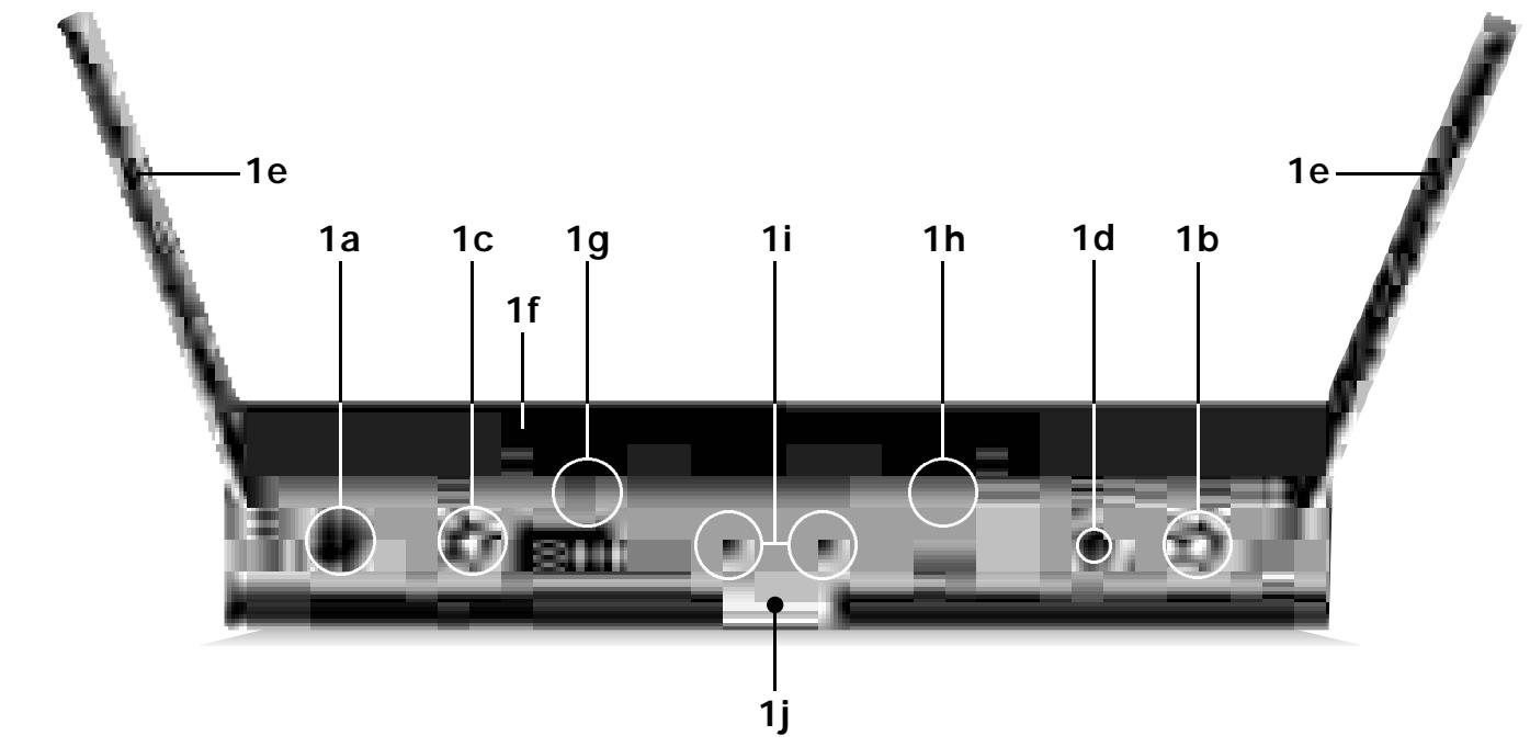
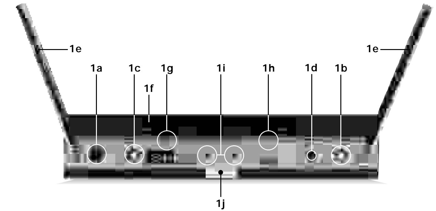
4.1.1. Front Panel
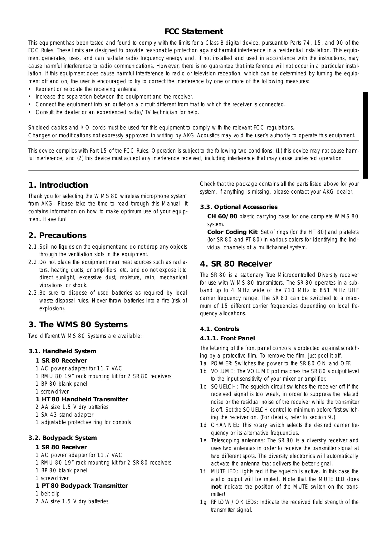
The lettering of the front panel controls is protected against scratching by a protective film. To remove the film, just peel it off.
1a POWER: Switches the power to the SR 80 ON and OFF.
1b VOLUME: The VOLUME pot matches the SR 80's output level to the input sensitivity of your mixer or amplifier.
1c SQUELCH: The squelch circuit switches the receiver off if the received signal is too weak, in order to suppress the related noise or the residual noise of the receiver while the transmitter is off. Set the SQUELCH control to minimum before first switching the receiver on. (For details, refer to section 9.)
1d CHANNEL: This rotary switch selects the desired carrier frequency or its alternative frequencies.
1e Telescoping antennas: The SR 80 is a diversity receiver and uses two antennas in order to receive the transmitter signal at two different spots. The diversity electronics will automatically activate the antenna that delivers the better signal.
1f MUTE LED: Lights red if the squelch is active. In this case the audio output will be muted. Note that the MUTE LED does not indicate the position of the MUTE switch on the transmitter!
1g RF LOW/OK LEDs: Indicate the received field strength of the transmitter signal.
1h AF/PEAK LEDs: Indicate the received audio level. The green LED lighting and the red LED flashing occasionally indicate optimum modulation. If the LEDs do not light, the sensitivity setting on the transmitter is too low. The red LED lighting constantly indicates overmodulation.
1i Diversity LEDs A and B: Indicate which of the two receiving antennas is active.
1j Color Code: If you use the receiver within a multichannel system, you may remove the black plastic platelet and replace it with a colored platelet included in the optional Color Coding Kit to identify each channel by a different color.
4.1.2. Rear Panel
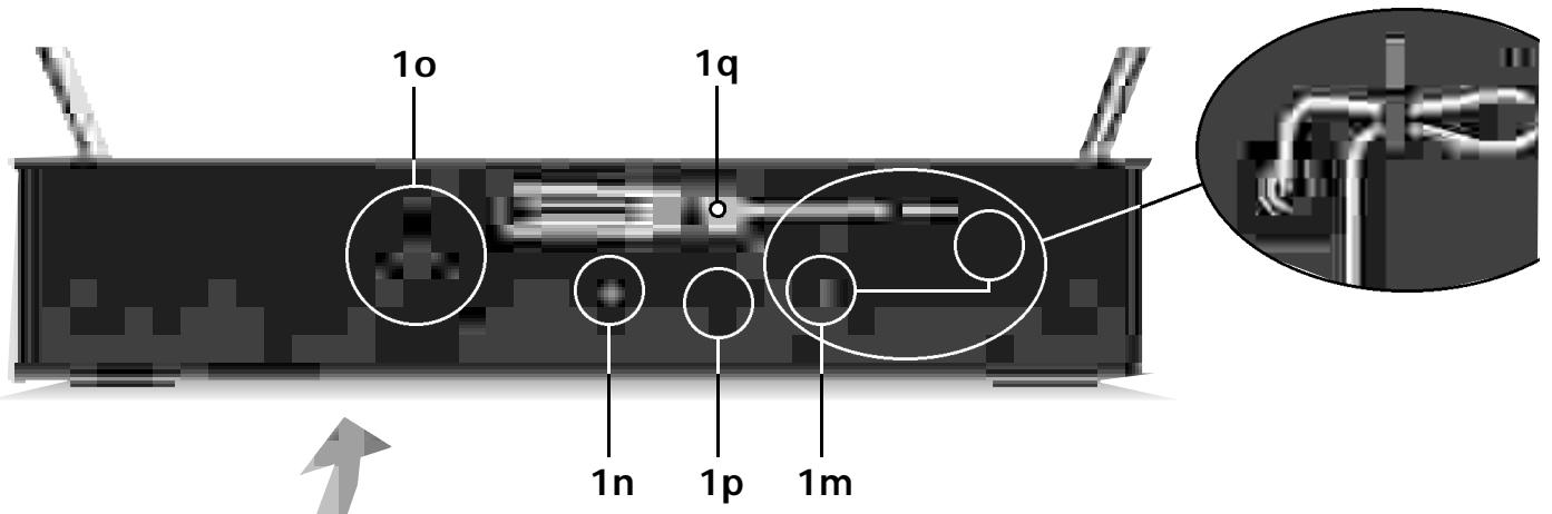
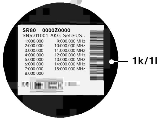
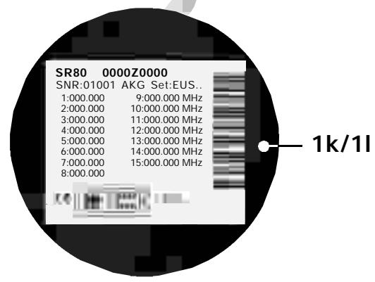
1k Carrier Frequency Table: A label listing the available frequencies is affixed to the bottom panel of the receiver.
11 Frequency Set Designation: The label on the bottom panel also indicates the designation of the Frequency Set.
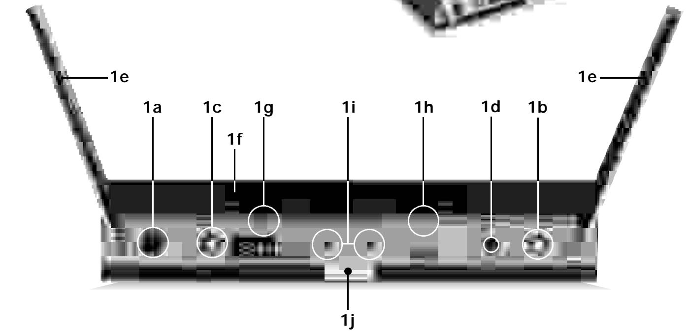
1m POWER: Input connector for the supplied AC adapter.
1n AUDIO OUT UNBALANCED: Unbalanced audio output on a 1 / 4'' mono jack for connecting to, e.g., a guitar amplifier.
10 AUDIO OUT BALANCED: Balanced 3-pin XLR audio output for connecting to, e.g., a microphone input on the mixing console.
1p BALANCED LINE/MIC: Switches the balanced audio output to line or microphone level. Therefore, you can connect the SR 80 to microphone or line level inputs as desired.
1q Screwdriver for adjusting the CHANNEL and GAIN controls on the transmitters.
4.2. Optional Accessories Color Coding Kit
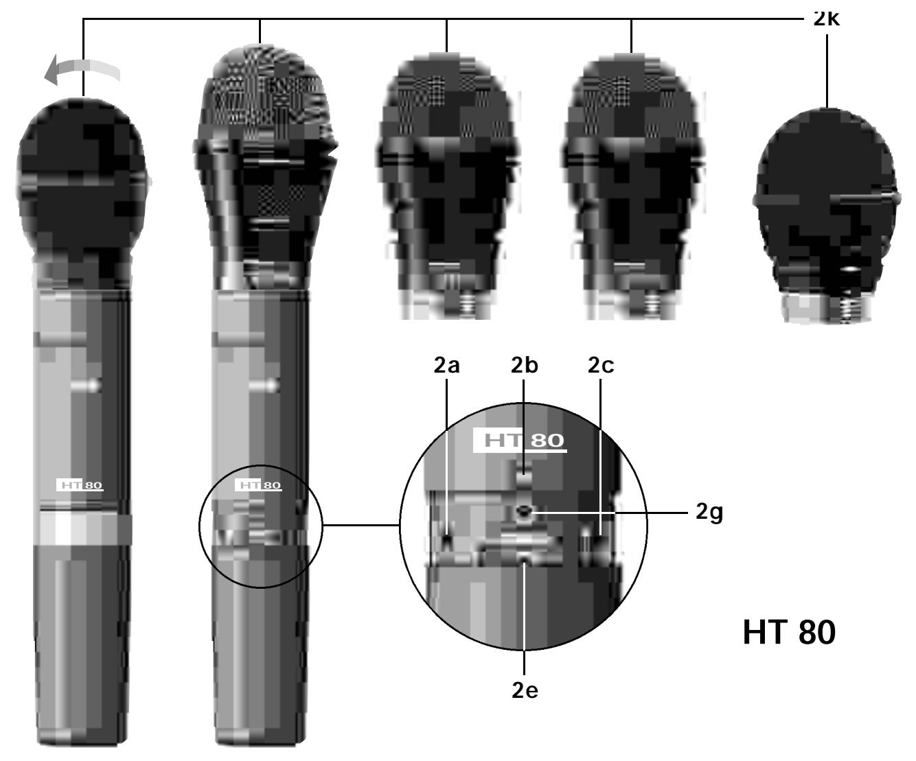
5. HT 80 Handheld Transmitter
The HT 80 handheld transmitter and matching microphone elements (optional) provide the same acoustic performance as the equivalent hardwire microphone versions. The microphone elements available for the HT 80 have been specifically designed for vocal use.
The HT 80 operates in a subband up to 4 MHz wide within the 710 MHz to 861 MHz UHF carrier frequency range. The HT 80 can be switched to a maximum of 15 different carrier frequencies depending on local frequency allocations.
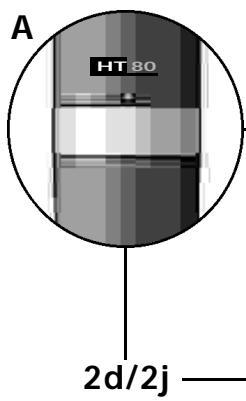
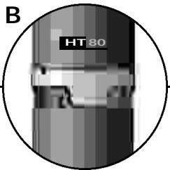
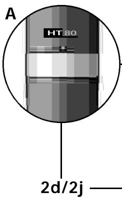
The transmitter uses a dipole antenna integrated in the body. The controls can be protected against accidental misadjustment collectively (2d) or individually with the supplied adjustable protective ring (2j).
5.1. HT 80 Controls
2a PWR: Switches the transmitter power ON ("I") and OFF ("O").
2b Status LED: Indicates battery status and audio input overload. LED glowing dimly: batteries are OK. LED constantly lighting brightly: batteries will be dead in about 90 minutes. LED illuminating brightly: audio input is overloaded.
2c MIC: Mutes the audio signal (position "0") while power and carrier frequency remain ON. Thus, no noise will become audible if you mute the microphone, even if the SQUELCH control (1c) on the receiver is set to minimum.
2d Color Code: If you use the transmitter in a multichannel system you can remove the black plastic ring and replace it with a colored ring from the optional Color Coding kit to identify
each wireless channel by a different color.
2e GAIN: This rotary pot allows you to match the microphone level to the transmitter's audio section.
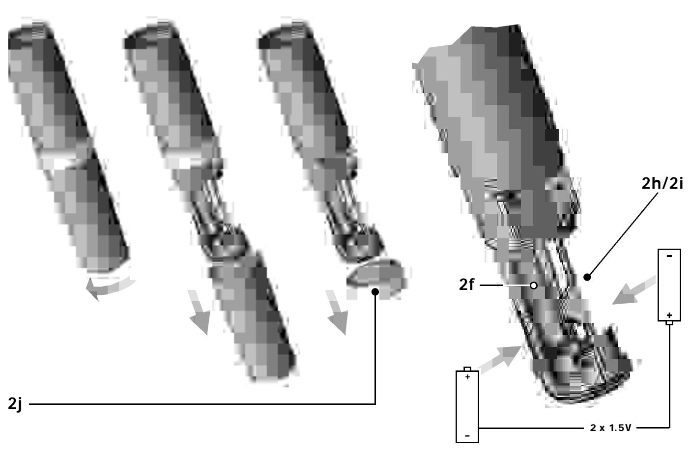
2f Battery Compartment: Refer to Section 9. Setting Up.
2g CHANNEL: This rotary switch selects the desired carrier frequency (depending on local allocations) or switches between the carrier frequency and its alternative frequencies.
Important: Prior to selecting frequencies, switch the transmitter OFF.
2h Carrier Frequency Table: A label listing the available frequencies is affixed to the battery compartment.
2i Frequency Set Designation: The label inside the battery compartment also indicates the designation of the Frequency Set.
2j Adjustable protective ring: Protects the controls from being misadjusted accidentally.
5.2. Interchangeable Microphone Elements
The interchangeable microphone elements (2k) D 880 WL1, D 3700 WL1, D 3800 WL1, C 5900 WL1, and C 535 WL1 are acoustically and mechanically identical to the equivalent hardwire versions. They feature the same transducer capsules and mechanical construction.
Extremely high gain before feedback, optimum handling noise rejection, ultimate protection from damage, and an integrated wind and pop screen are only the most impressive features of these microphones. For more details, refer to the respective AKG brochures.
5.3. Optional Accessories
W 880 foam windscreen for D 880 WL1
W 3001 foam windscreen for D 3700 WL1 and C 5900 WL1
W 23 foam windscreen for C 535 WL1 Color Coding Kit
6. PT 80 Bodypack Transmitter
You can use the PT 80 bodypack transmitter with both dynamic microphones and condenser microphones operating on a supply voltage of approx. 7 V. You may also connect an electric guitar, electric bass, or remote keyboard.
The PT 80 operates in a subband up to 4 MHz wide of the 710 MHz to 861 MHz UHF carrier frequency range. The HT 80 can be switched to a maximum of 15 different carrier frequencies depending on local frequency allocations.
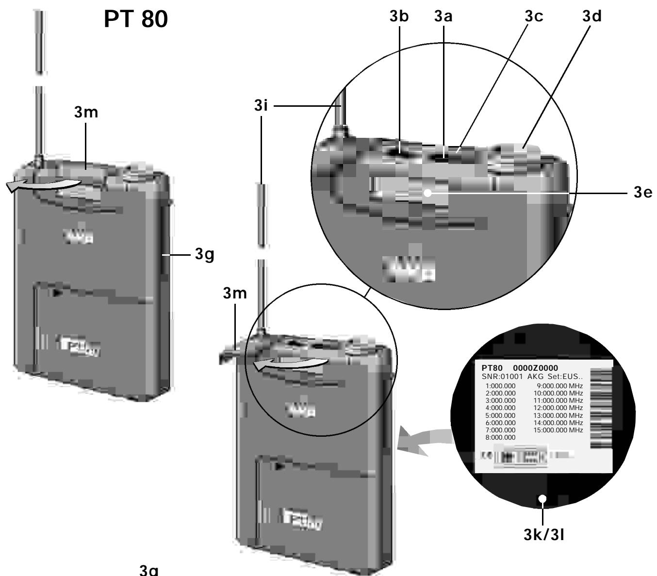
6.1. Controls
3a POWER: Switches the transmitter power ON ("l") and OFF ("O").
3b MIC: Mutes the audio signal (position "O") while power and carrier frequency remain ON. Thus, no noise will become audible if you mute the microphone even if the SQUELCH control (1c) on the receiver is set to minimum.
3c Status LED: Indicates battery status and audio input overload. LED glowing dimly: batteries are OK. LED constantly lighting brightly: batteries will be dead in about 90 minutes. LED illuminating brightly: audio input is overloaded.
3d Audio Input: 3-pin mini XLR connector with both mic and line level pins that automatically match the connector pinout of the microphone or optional MKG/L guitar cable.
3e Color Code: If you use the transmitter within a multichannel system, you may remove the black plastic platelet and replace it with a colored platelet included in the optional Color Coding Kit to identify each channel by a different color.
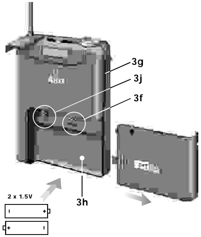
3f CHANNEL: This rotary switch selects the desired carrier frequency.
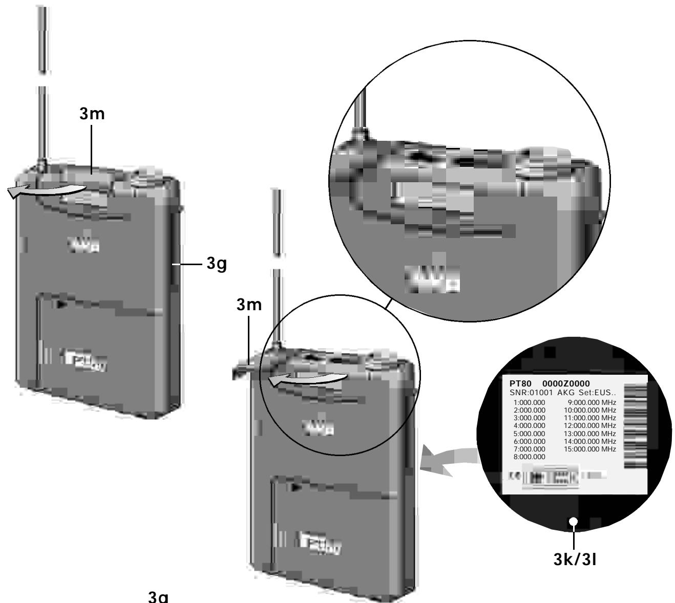
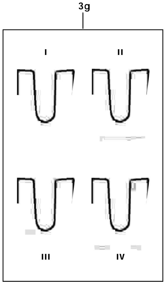
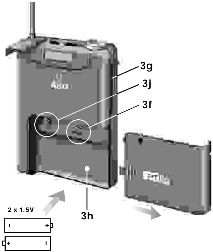
3g Belt Clip for fixing the transmitter to your belt.
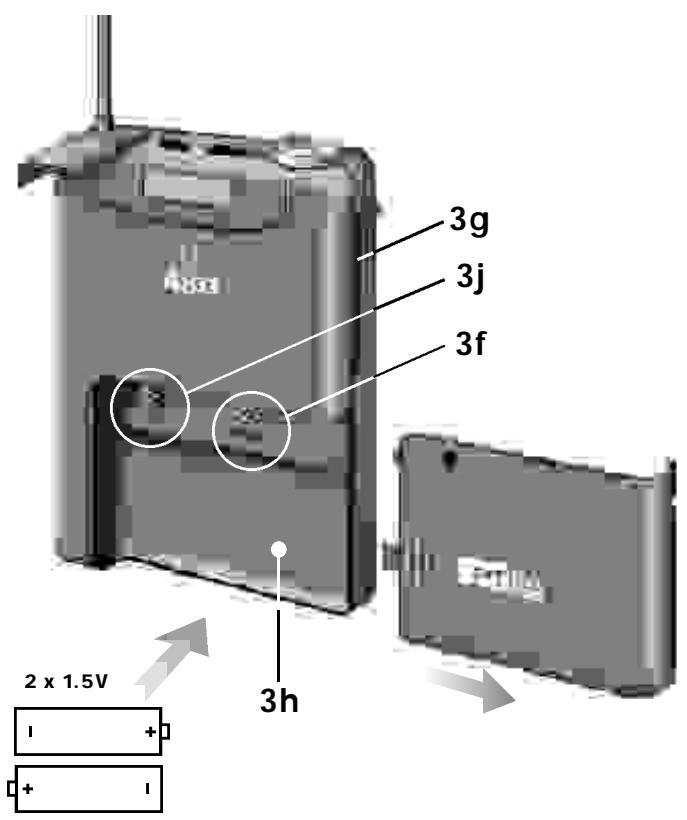
3h Battery Compartment: Refer to Section 9. Setting Up.
3i Antenna: Permanently connected, flexible antenna.
3j GAIN: This rotary pot allows you to match the microphone or instrument level to the transmitter's audio section.
3k Carrier Frequency Table: A label listing the available frequencies is affixed to the transmitter rear panel.
31 Frequency Set Designation: The label on the rear panel also indicates the designation of the Frequency Set.
3m Security Cover: Protects the POWER and MIC switches from being actuated unintentionally.
6.2. Microphones, Guitar Cable (optional)
The following AKG microphones have been designed specifically for direct connection to the audio input of the PT 80:
C 417 L
C 419 L
C 420 L
CK77L
The MKG/L guitar cable from AKG lets you connect an electric guitar, electric bass, or remote keyboard to the bodypack transmitter.
6.3. Optional Accessories
CB 60/80 bag
Color Coding Kit
7. Frequencies
The transmitter and receiver of your WMS 80 system have been factory programmed for up to 15 selectable carrier frequencies. The carrier frequency label (1k) on the receiver, (2g) on the handheld transmitter, or (3k) on the bodypack transmitter lists the Frequency Set your WMS 80 system uses and all available carrier frequencies.
7.1. Frequency Sets
Prior to powering up your WMS 80 system, check that the transmitter and receiver use the same Frequency Set. If they do not, you may not be able to find a common carrier frequency for the transmitter and receiver.
The following Frequency Sets are currently available:
| Designation | Frequency Range (MHz) | Countries |
| EU58 | 770,6 - 773,4 | EU |
| EU59 | 777,6 - 780,4 | EU |
| EU60 | 785,6 - 788,4 | EU |
| JPA | 802,5 - 805,5 | EU, Japan |
| NZ1 | 812,2 - 815,0 | EU, New Zealand |
| NZ2 | 833,2 - 835,0 | EU, New Zealand |
| UK69A | 854,9 - 857,625 | EU, Great Britain |
| UK69B | 858,2 - 860,9 | EU, Great Britain |
| US54 | 710,2 - 713,0 | USA |
| US55 | 719,0 - 721,8 | USA |
| US58 | 734,4 - 737,2 | USA |
| US59 | 742,8 - 745,6 | USA |
For frequencies allocated in the various countries and frequencies suited for intermodulation-free simultaneous operation, refer to the Frequency List in section 12.
7.2. Ordering Transmitters and Receivers
If you want to order additional transmitters or receivers operating
on the same set of frequencies as your original equipment, be sure to state the designation of your original Frequency Set (1k/1l, 2i, 3k/3l) and the serial number of the original device. We need this information to make sure your new equipment will be compatible with the original units.
8. Multichannel Systems
Carrier frequencies allocated to wireless microphones differ from country to country. Depending on local frequency allocations and available carrier frequencies you can operate two to four WMS 80 systems simultaneously. (Refer to the Frequency List in section 12.)
In each carrier frequency table (1k, 2h, 3k) and in the Frequency List in section 12, the basic frequencies you can use simultaneously and without risk of intermodulation are marked with .
If you have any questions regarding allocated frequencies contact your dealer, the competent authority, your AKG representative, or the AKG head office in Vienna, Austria.
Alternatively, you are welcome to visit the AKG website at www.akg-acoustics.com where you can download a FREE frequency management program for AKG Wireless Microphone Systems.
9. Setting Up
Prior to connecting the receiver to AC power and inserting the batteries into the transmitter, set the transmitter and receiver to the same carrier frequency. The carrier frequency tables on the transmitter (2h, 3k) and receiver (1k) and the Frequency List (section 12) on page 44 list the channel number corresponding to each carrier frequency.
9.1. Selecting the Carrier Frequency
- Handheld transmitter: Unscrew the battery compartment cover and the color code ring (2d or 2j) CCW.
Bodypack transmitter: Open the battery compartment (3h).
All controls are now accessible.
- Use the supplied screwdriver (1q) to set the CHANNEL control (2g) on the handheld transmitter or (3f) on the bodypack transmitter to the desired channel.
- Set the CHANNEL control (1d) on the receiver to the same channel as the transmitter.
9.1.1. Multichannel Systems
- Be sure to assign a separate carrier frequency to each transmission channel (transmitter + receiver).
- Set the transmitter and receiver to one of the frequencies marked with in the carrier frequency tables (1k, 2h, 3k).
Note: If reception on the selected carrier frequency is disturbed, set the carrier frequencies for all WMS 80 channels within the same frequency set up or down one step with the respective CHANNEL controls (1d, 2g, 3f) on each transmitter and receiver.
This is necessary to provide the minimum frequency spacing required for intermodulation-free multichannel operation.
Important: Do not operate two or more WMS 80 channels on the same frequency at the same time and location. This would cause unwanted noise due to radio interference.
9.1.2. Changing Carrier Frequencies
Prior to changing a carrier frequency, be sure to switch the
transmitter OFF. To activate the new carrier frequency, switch the transmitter back ON. (If you try to change the carrier frequency while power to the transmitter is on, the frequency will remain the same.)
9.2. HT 80 Handheld Transmitter
9.2.1. Microphone Element
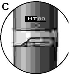
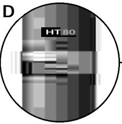
Prior to switching the transmitter on, screw the microphone element CW onto the thread on the transmitter. All electrical connections will be made automatically.
9.2.2. Inserting, Testing, and Removing Batteries
- Make sure that the end of the ribbon fixed inside the battery compartment (2f) will stick out of the battery compartment (2f). (The ribbon is needed for removing the batteries.)
- Push the upper end of each of the supplied batteries beneath the fixing flange in the battery compartment (2f) from the side and press firmly down against the battery compartment bottom. Check that the batteries align with the polarity marks.
The transmitter will not function with the batteries inserted incorrectly
Important: Do not try to insert the batteries straight or with the lower end first. You would risk breaking the fixing flange so the battery would not be seated securely in the battery compartment.
3. Set the PWR switch to "1" to switch the power to the transmitter on.
The status LED (2b) will flash momentarily. If the batteries are in good condition, the status LED (2b) will continue glowing dimly.
When the status LED (2b) illuminates brightly the batteries will be dead within about 90 minutes. Replace the batteries with new ones as soon as possible.
If the status LED (2b) fails to illuminate the batteries are dead. Insert new batteries.
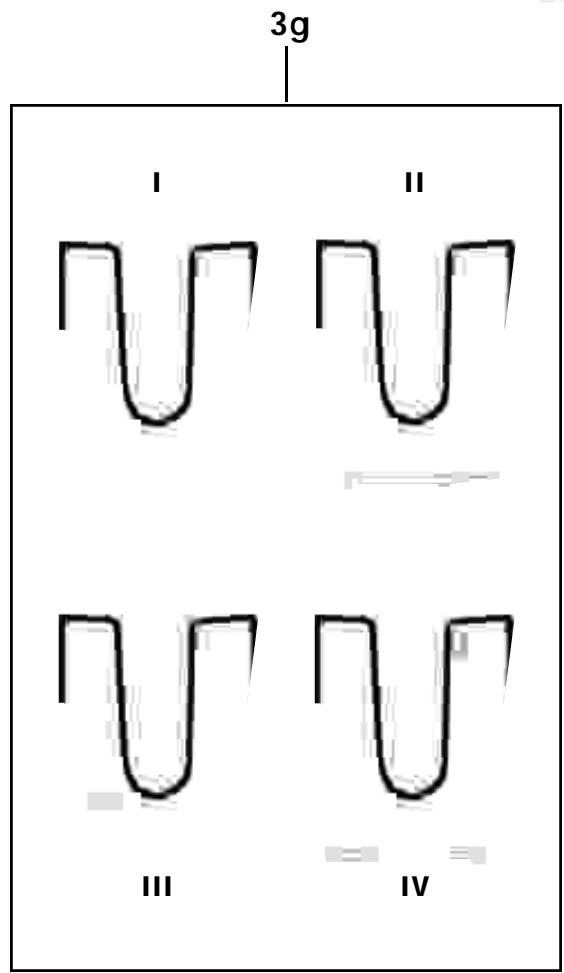
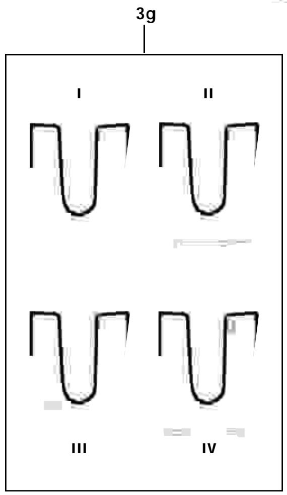
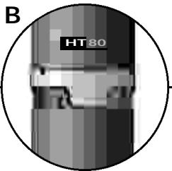
- Screw the supplied protective ring (2j) and the battery compartment cover back onto the transmitter CW. You can rotate the protective ring (2j) so that any one of the controls will be accessible and all others covered (B to E) and thus protected from being misadjusted unintentionally.
Note: For easy channel identification in a multichannel setup, you can install a different-color protective ring included in the optional Color Coding Kit. These protective rings are adjustable, too.
Note: If you prefer to cover all controls, reinstall the original color code ring (2d) after adjusting the system as described in section 9.5. - Removing batteries: Pull the ribbon outward to release the batteries from the battery compartment (2f) and remove the batteries.
9.3. PT 80 Bodypack Transmitter
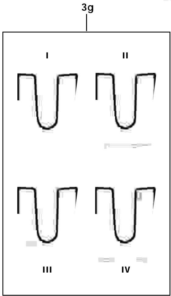
- Insert the supplied batteries into the battery compartment (3h) conforming to the polarity marks.
The transmitter will not function with incorrectly inserted batteries. - Close the battery compartment (3h). The GAIN control (3j) remains accessible through an opening in the battery compartment cover.
- Connect your microphone -- or your instrument using an optional MKG/L guitar cable -- to the audio input (3d).
- Rotate the security cover (3m) CW to uncover the switches.
- Set the POWER switch (3a) to "1" to switch the power to the transmitter on.
The status LED (3c) will flash momentarily. If the batteries are in
good condition, the status LED (3c) will continue glowing dimly. When the status LED (3c) illuminates brightly the batteries will be dead within about 90 minutes. Replace the batteries with new ones as soon as possible.
If the status LED (3c) fails to illuminate the batteries are dead. Insert new batteries.
- Snap the security cover (3m) back over the switches CCW. You can wear the transmitter inside a shirt or jacket pocket, fix it to your belt with the belt clip (3g), or attach it to your body with adhesive bandage.
Important: Make sure the antenna will hang down freely, without being covered by the body.
Note: For easy channel identification in a multichannel setup, you can replace the snap fitted color code platelet (3e) with a different-color platelet included in the optional Color Coding Kit.
9.4. SR 80 Receiver
9.4.1. Placement
Reflections off metal parts, walls, ceilings, etc. or the shadow effects of musicians and other people may weaken or cancel the direct transmitter signal.
For best results, place the receiver as follows:
- Place the receiver near the performance area (stage). Make sure, though, that the transmitter will never get any closer to the receiver than 16 ft. (5 m).
- There should always be a direct line of sight between the transmitter and receiver.
- Place the receiver at least 5 ft. (1.5 m) away from any big metal objects, wire (particularly wire mesh) or sheet metal structures, walls, scaffolding, ceilings, etc.
- Do not place the receiver in a recess in a wall.
- Place the receiver at least 5 ft. (1.5 m) away from any equipment that may emit RF radiation such as lighting racks, fluorescent lamps, digital effects units, or PCs.
You can either use the receiver free-standing or mount it in a 19" rack using the supplied RMU 80 rack mounting kit.
9.4.2. Rack Mounting
- Slide a rack ear into the fixing rail on one side of the receiver and the BP 80 blank panel into the fixing rail on the other side from rear to front.
- To mount two receivers, slide the linking section with the cover plate pointing to the receiver front panel into the fixing rail on one side of the receiver from rear to front. Slide the linking section into the fixing rail on one side of the second receiver from the rear. Slide another rack ear into the fixing rail on the other side of the second receiver.
- Use the supplied installation screws to fix the rack ears to the rack. For best reception, we recommend to mount the receiver(s) at the top level of the rack.
9.4.3. Audio Connection
Connect one of the AUDIO OUT sockets to the desired input:
- BALANCED socket (1o) - XLR cable - microphone input: set BALANCED LINE/MIC switch (1p) to MIC.
- BALANCED socket (1o) - XLR cable - line input: set BALANCED LINE/MIC switch (1p) to LINE.
- UNBALANCED jack (1n) - 1/4" jack cable - unbalanced 1/4" microphone or line input jack. (BALANCED LINE/MIC switch (1p) position is uncritical.)
Important: Never use the two AUDIO OUT sockets simultaneously! This may cause signal loss or increased noise.
9.4.4. Connecting to Power
- Unfold the two antennas (1e) and extend them fully to obtain optimum reception.
- Set the SQUELCH control (1c) fully CCW.
- Check that the AC mains voltage stated on the supplied AC adapter is identical to the AC mains voltage available where you will use your WMS 80. Using the AC adapter with a different AC voltage may cause irreparable damage to the unit.
- Plug the feeder cable on the supplied AC adapter into the POWER socket (1m) on the receiver.
- Bend part of the feeder cable into a bight, pass the bight through the opening in the lower part of the screwdriver support, and place the end of the bight snugly against the strain relief hook above the POWER socket (1m).
- Plug the power cable on the supplied AC adapter into a convenient power outlet.
- Switch the receiver ON with the POWER switch (1a).
Note: For easy channel identification in a multichannel setup, you can replace the snap fitted color code platelet (1j) with a different-color platelet included in the optional Color Coding Kit.
9.4.5.Antennas
For optimum reception, make sure to extend the two telescoping antennas (1e) exactly as far as specified for each Frequency Set in Table 1 on page 39.
9.5. System Adjustments
- Handheld transmitter: Using the supplied screwdriver (1q), set the GAIN control (2e) so that on the receiver the green AF LED (1h) will light constantly and the red PEAK LED (1h) on the receiver and the status LED (2b) on the transmitter will only flash on the loudest signal peaks.
Bodypack transmitter: Using the supplied screwdriver (1q), set the GAIN control (3j) so that the green AF LED (1h) on the receiver will light constantly and the status LED (3c) on the transmitter as well as the red PEAK LED (1h) on the receiver will only flash on the loudest signal peaks.
- The red PEAK LED (1h) on the receiver and/or the status LED (2b, 3c) on the transmitter lighting brightly means the transmitter is overloaded. Turn the GAIN control (2e) or (3j) on the transmitter CCW to the point that the PEAK (1h) and status (3c) LEDs will only flash occasionally.
- Set the VOLUME control (1b) on the receiver so that the receiver output will optimally drive the connected device (e.g., mixer input). Refer to the instruction manual for the connected device.
- Check the performance area for "dead spots", i.e., places where the field strength seems to drop and reception deteriorates. If you find any dead spots, try to eliminate them by repositioning the receiver. If this does not help, avoid the dead spots.
- If unwanted noise becomes audible, turn the SQUEELCH control (1c) CW just enough to suppress the noise.
The MUTE LED (1f) will light every time the squelch mutes the audio output of the receiver.
Important: Never set the squelch threshold higher than absolutely necessary. The higher the squelch threshold, the lower the sensitivity of the receiver and thus the usable range between transmitter and receiver.
6. Check the field strength of the received signal. If the RF LOW LED (1g) lights, reposition the receiver and/or transmitter such that field strength will increase back to optimum (OK LED (1g) illuminating).
7. The MUTE LED (1f) on the receiver illuminating means that the squelch is active.
Remedies: Switch the transmitter ON, move closer to the receiver, or turn the SQUELCH control (1c) CCW to the point that the MUTE LED (1f) will extinguish.
9.5.1. Multichannel Systems
If reception on the selected carrier frequency is disturbed, set the carrier frequencies for all WMS 80 channels within the same frequency set up or down one step with the respective CHANNEL controls (1d, 2g, 3f) on each transmitter and receiver.
This is necessary to provide the minimum frequency spacing required for intermodulation-free multichannel operation.
Important: Prior to changing a carrier frequency, be sure to switch the transmitter OFF. To activate the new carrier frequency, switch the transmitter back ON. (If you try to change the carrier frequency while power to the transmitter is on, the frequency will remain the same.)
9.6. Important Hints for Reliable Operation
The propagation of RF radiation is subject to certain physical laws that you need to take into account in order to obtain trouble-free performance from any wireless microphone system. Here are a few useful hints on how to avoid problems such as sudden noise surges, phasiness (whizzing, whirring), dropouts, or clicks:
- In a multichannel system, always leave power to all transmitters on. To cut the transmitter signal, use the MUTE switch only.
- Keep a minimum transmitter to receiver distance of 16 ft. (5 m).
- Make sure the transmitter will never be farther away from the receiver than 164 ft. (50 m).
- Make sure there is a direct line of sight between the transmitter and receiver.
- Keep any two transmitters at least 40 inches (1 m) apart. If this is impractical (for instance, during "love duets"), check prior to the performance what frequencies will work best at close quarters.
- Make sure the antenna of the bodypack transmitter will hang down freely throughout the performance and will not touch the user's skin. The human body attenuates RF signals.
- Do not place the receiver in a recess in a wall or near sheet metal or wire structures. Wire mesh is a particularly efficient absorber of RF energy.
- Do not align antennas parallel to metal surfaces.
- Avoid lighting racks and fluorescent lamps. Dimmers and ballast circuits emit RF radiation.
- Avoid digital effects units and PCs. They, too emit RF radiation.
10. Cleaning
To clean the transmitter and receiver surfaces, use a soft cloth moistened with methylated spirits or alcohol.
11. Specifications
| HT 80 | PT 80 | SR 80 | |
| Carrier frequency | 710.2 to 860.9 MHz | ||
| Modulation | FM | ||
| Audio bandwidth | 50 to 20,000 Hz | ||
| Frequency stability (-10°C to +50°C) | ±10 ppm | ||
| Rated deviation | 30 kHz (US1a, US1b: 7.5 kHz) | ||
| T.H.D. at 1 kHz | <0.5% | <0.4% | |
| Compander | Yes | ||
| Signal/noise ratio | typ. 50 dB(A) | >100 dB(A) | |
| Limiter | Yes | ||
| RF output | 10 mW | ||
| Current consumption | typ. 130 mA | 145 mA | 200 mA |
| Power requirement | 2x1.5 V AA size batteries | 120/230 V AC, 50/60 Hz | |
| Battery life | >8 hours | >8 hours | |
| Input sensitivity | typ. -95 dBm | ||
| Audio input level for rated deviation | 350 mV/1 kHz | 1400 mV/1 kHz | |
| Input impedance | 220 k | ||
| Condenser microphone power supply | 6 V/6,8 k on pin 3 | ||
| Squelch threshold | -95 to -80 dBm | ||
| Audio output | balanced XLR: switchable be tween microphone and line levels; typ. 30 dB unbalanced XLR: 6 dBm unbalanced 1/4" jack: 0 dBm | ||
| Size (WxDxH) | 240 x 36 dia. mm(9.4 x 1.4 in.) | 92 x 65 x 20 mm(3.6 x 2.6 x 0.8 in.) | 210 x 170 x 42 mm(8.3 x 6.7 x 1.7 in.) |
| Net weight | 245 g (8.7 oz.) | 76 g (2.7 oz.) | 470 g (16.6 oz.) |
This product conforms to ETS 300.422 and ETS 300.445 as well as Parts 15 (receiver), 74, and 90 (traveler) of the FCC Rules.
12. Frequenzliste - Frequency List -(Liste des fréquences - Lista delle frequenze - Lista de frequencies - Lista de frequencies
| Set: JPA (Japan Spot) | Set: UK69A (UKSpot) | Set: UK69B (UKSpot) | |||
| CHANNEL | FREQ. | CHANNEL | FREQ. | CHANNEL | FREQ. |
| 0 | OFF | 0 | OFF | 0 | OFF |
| 1 | 802.500MHz* | 1 | 854.900MHz* | 1 | 858.200MHz* |
| 2 | 803.000MHz* | 2 | 855.275MHz* | 2 | 860.400MHz* |
| 3 | 804.000MHz | 3 | 856.175MHz* | 3 | 860.900MHz* |
| 4 | 804.875MHz* | 4 | 857.625MHz* | 4 | 860.900MHz |
| 5 | 805.500MHz* | 5 | 857.625MHz | 5 | 860.900MHz |
| 6 | 805.500MHz | 6 | 857.625MHz | 6 | 860.900MHz |
| 7 | 805.500MHz | 7 | 857.625MHz | 7 | 860.900MHz |
| 8 | 805.500MHz | 8 | 857.625MHz | 8 | 860.900MHz |
| 9 | 805.500MHz | 9 | 857.625MHz | 9 | 860.900MHz |
| A | 805.500MHz | A | 857.625MHz | A | 860.900MHz |
| B | 805.500MHz | B | 857.625MHz | B | 860.900MHz |
| C | 805.500MHz | C | 857.625MHz | C | 860.900MHz |
| D | 805.500MHz | D | 857.625MHz | D | 860.900MHz |
| E | 805.500MHz | E | 857.625MHz | E | 860.900MHz |
| F | 805.500MHz | F | 857.625MHz | F | 860.900MHz |
| Set: US54 | Set: US55 | Set: US58 | |||
| CHANNEL | FREQ. | CHANNEL | FREQ. | CHANNEL | FREQ. |
| 0 | OFF | 0 | OFF | 0 | OFF |
| 1 | 710.200MHz | 1 | 719.000MHz | 1 | 734.400MHz |
| 2 | 710.400MHz* | 2 | 719.200MHz | 2 | 734.600MHz* |
| 3 | 710.600MHz | 3 | 719.400MHz | 3 | 734.800MHz |
| 4 | 710.800MHz | 4 | 719.600MHz | 4 | 735.000MHz |
| 5 | 711.000MHz* | 5 | 719.800MHz* | 5 | 735.200MHz |
| 6 | 711.200MHz | 6 | 720.000MHz | 6 | 735.400MHz |
| 7 | 711.400MHz | 7 | 720.200MHz | 7 | 735.600MHz |
| 8 | 711.600MHz | 8 | 720.400MHz | 8 | 735.800MHz |
| 9 | 711.800MHz* | 9 | 720.600MHz* | 9 | 736.000MHz* |
| A | 712.000MHz | A | 720.800MHz | A | 736.200MHz |
| B | 712.200MHz | B | 721.000MHz | B | 736.400MHz |
| C | 712.400MHz | C | 721.200MHz | C | 736.600MHz |
| D | 712.600MHz | D | 721.400MHz | D | 736.800MHz |
| E | 712.800MHz* | E | 721.600MHz* | E | 737.000MHz* |
| F | 713.000MHz | F | 721.800MHz | F | 737.200MHz |
| Set: US59 | Set: EU58 | Set: EU59 | |||
| CHANNEL | FREQ. | CHANNEL | FREQ. | CHANNEL | FREQ. |
| 0 | OFF | 0 | OFF | 0 | OFF |
| 1 | 742.800MHz | 1 | 770.600MHz | 1 | 777.600MHz |
| 2 | 743.000MHz* | 2 | 770.800MHz* | 2 | 777.800MHz* |
| 3 | 743.200MHz | 3 | 771.000MHz | 3 | 778.000MHz |
| 4 | 743.400MHz | 4 | 771.200MHz | 4 | 778.200MHz |
| 5 | 743.600MHz* | 5 | 771.400MHz* | 5 | 778.400MHz* |
| 6 | 743.800MHz | 6 | 771.600MHz | 6 | 778.600MHz |
| 7 | 744.000MHz | 7 | 771.800MHz | 7 | 778.800MHz |
| 8 | 744.200MHz | 8 | 772.000MHz | 8 | 779.000MHz |
| 9 | 744.400MHz* | 9 | 772.200MHz* | 9 | 779.200MHz* |
| A | 744.600MHz | A | 772.400MHz | A | 779.400MHz |
| B | 744.800MHz | B | 772.600MHz | B | 779.600MHz |
| C | 745.000MHz | C | 772.800MHz | C | 779.800MHz |
| D | 745.200MHz | D | 773.000MHz | D | 780.000MHz |
| E | 745.400MHz* | E | 773.200MHz* | E | 780.200MHz* |
| F | 745.600MHz | F | 773.400MHz | F | 780.400MHz |
| Set: EU60 | Set: NZ1 | Set: NZ2 | |||
| CHANNEL | FREQ. | CHANNEL | FREQ. | CHANNEL | FREQ. |
| 0 | OFF | 0 | OFF | 0 | OFF |
| 1 | 785.600MHz | 1 | 812.200MHz | 1 | 833.200MHz |
| 2 | 785.800MHz* | 2 | 812.400MHz* | 2 | 833.400MHz* |
| 3 | 786.000MHz | 3 | 812.600MHz | 3 | 833.600MHz |
| 4 | 786.200MHz | 4 | 812.800MHz | 4 | 833.800MHz |
| 5 | 786.400MHz* | 5 | 813.000MHz* | 5 | 834.000MHz* |
| 6 | 786.600MHz | 6 | 813.200MHz | 6 | 834.200MHz |
| 7 | 786.800MHz | 7 | 813.400MHz | 7 | 834.400MHz |
| 8 | 787.000MHz | 8 | 813.600MHz | 8 | 834.600MHz |
| 9 | 787.200MHz* | 9 | 813.800MHz* | 9 | 834.800MHz* |
| A | 787.400MHz | A | 814.000MHz | A | 835.000MHz |
| B | 787.600MHz | B | 814.200MHz | B | 835.200MHz |
| C | 787.800MHz | C | 814.400MHz | C | 835.400MHz |
| D | 788.000MHz | D | 814.600MHz | D | 835.600MHz |
| E | 788.200MHz* | E | 814.800MHz* | E | 835.800MHz* |
| F | 788.400MHz | F | 815.000MHz | F | 836.000MHz |
WMS 80
Wireless Microphone System

HT 80


WMS 80
Wireless Microphone Systems

Mode d'emploi
Table des Matieres
Page
Wireless Microphone System


HT 80


WMS 80
Wireless Microphone Systems

Istruzioni d'uso
Wireless Microphone System


HT 80


WMS 80
Wireless Microphone Systems

Modo de empleo
Wireless Microphone System


HT 80


WMS 80
Wireless Microphone Systems
Instruções de uso
9.1.2 mushar as frequencies portadoras
Wireless Microphone System


HT 80


- Wireless Microphone Systems
- WMS 80
- Contents
- FCC Statement
- Introduction
- Precautions
- The WMS 80 Systems
- Handheld System
- Bodypack System
- Optional Accessories
- SR 80 Receiver
- Controls
- Front Panel
- Rear Panel
- Optional Accessories Color Coding Kit
- HT 80 Handheld Transmitter
- HT 80 Controls
- Interchangeable Microphone Elements
- Optional Accessories
- PT 80 Bodypack Transmitter
- Controls
- Microphones, Guitar Cable (optional)
- Optional Accessories
- Frequencies
- Frequency Sets
- Ordering Transmitters and Receivers
- Multichannel Systems
- Setting Up
- Selecting the Carrier Frequency
- Multichannel Systems
- Changing Carrier Frequencies
- HT 80 Handheld Transmitter
- Microphone Element
- Inserting, Testing, and Removing Batteries
- PT 80 Bodypack Transmitter
- SR 80 Receiver
- Placement
- Rack Mounting
- Audio Connection
- Connecting to Power
- 9.4.5.Antennas
- System Adjustments
- Multichannel Systems
- Important Hints for Reliable Operation
- Cleaning
- Specifications
- Frequenzliste - Frequency List -(Liste des fréquences - Lista delle frequenze - Lista de frequencies - Lista de frequencies
- Table des Matieres
- mushar as frequencies portadoras
Brand : AKG
Model : WMS 80
Category : Wireless Microphone System