
SR 40 FLEXX - Wireless Microphone System AKG - Free user manual and instructions
Find the device manual for free SR 40 FLEXX AKG in PDF.

| Product Type | Diversity stationary receiver for wireless microphone systems |
| Brand | AKG |
| Model | SR 40 FLEXX |
| Frequency Range | UHF 660 - 865 MHz (depending on version) |
| Number of switchable frequencies | 3 per band |
| Reception Type | Diversity, two active antennas |
| Modulation | FM |
| Audio Bandwidth | 35 - 20,000 Hz |
| Harmonic Distortion | Typ. 0.8% at 1 kHz |
| Signal-to-Noise Ratio | Typ. 110 dB(A) |
| Compander | Yes |
| Squelch Threshold | Adjustable from -100 to -70 dBm |
| Audio Outputs | Balanced XLR and unbalanced 6.35 mm jack, adjustable mic/line level |
| Power Supply | 120/230 V AC, 50/60 Hz via 12 V DC power adapter |
| Power Consumption | 115 mA at 12 V |
| Dimensions (W × D × H) | 200 × 190 × 44 mm |
| Net Weight | 665 g |
| Housing | Metal, 9.5 inches, 19" rack compatible |
| Included Accessories | Power adapter, user manual, "Manual Supplement" appendix |
| Maintenance | Clean with a soft damp cloth, disconnect before |
| Safety | Do not expose to moisture, use only the supplied adapter |
| Environment | Disconnect the adapter if not used for extended periods, recycle packaging |
Frequently Asked Questions - SR 40 FLEXX AKG
User questions about SR 40 FLEXX AKG
0 question about this device. Answer the ones you know or ask your own.
Ask a new question about this device
Download the instructions for your Wireless Microphone System in PDF format for free! Find your manual SR 40 FLEXX - AKG and take your electronic device back in hand. On this page are published all the documents necessary for the use of your device. SR 40 FLEXX by AKG.
USER MANUAL SR 40 FLEXX AKG
Please read the manual before using the equipment!
MODE D'EMPLOI p.21
1 Safety and Environment 13
1.1 Safety 13
1.2 Environment 13
2 Description. 14
2.1 Introduction 14
2.2 Packing List 14
2.3 Optional Accessories 14
2.4 SR 40 FLEXX Receiver 14
2.4.1 Front Panel Controls 14
2.4.2 Rear Panel 15
3 Setting Up 16
3.1 Positioning the Receiver 16
3.2 Connecting the Receiver to a Balanced Input 16
3.3 Connecting the Receiver to an Unbalanced Input 16
3.4 Connecting the Receiver to Power 17
3.5 Setting Frequencies 17
3.6 Before the Soundcheck 18
3.7 Multichannel Systems 18
3.8 Changing Carrier Frequencies (HT 40 FLEXX, PT 40 FLEXX) 18
4 Cleaning. 19
5 Troubleshooting 19
6 Specifications 20
Fig. 6 .57
FCC Statement
This equipment has been tested and found to comply with the limits for a Class B digital device, pursuant to Part 15 of the FCC Rules. These limits are designed to provide reasonable protection against harmful interference in a residential installation. This equipment generates, uses, and can radiate radio frequency energy and, if not installed and used in accordance with the instructions, may cause harmful interference to radio communications. However, there is no guarantee that interference will not occur in a particular installation. If this equipment does cause harmful interference to radio or television reception, which can be determined by turning the equipment off and on, the user is encouraged to try to correct the interference by one or more of the following measures:
Reorient or relocate the receiving antenna.
- Increase the separation between the equipment and the receiver.
- Connect the equipment into an outlet on a circuit different from that to which the receiver is connected.
- Consult the dealer or an experienced radio/TV technician for help.
Shielded cables and I/O cords must be used for this equipment to comply with the relevant FCC regulations.
Changes or modifications not expressly approved in writing by AKG Acoustics may void the user's authority to operate this equipment.
This device complies with Part 15 of the FCC Rules. Operation is subject to the following two conditions: (1) this device may not cause harmful interference, and (2) this device must accept any interference received, including interference that may cause undesired operation.
1 Safety and Environment

1.1 Safety
- Do not spill any liquids on the equipment and do not drop any objects through the ventilation slots in the equipment.
- The equipment may be used in dry rooms only.
- The equipment may be opened, serviced, and repaired by authorized personnel only. The equipment contains no user-serviceable parts.
- Before connecting the equipment to power, check that the AC mains voltage stated on the supplied AC adapter is identical to the AC mains voltage available where you will use the equipment.
- Operate the equipment with the supplied AC adapter with a 12-VDC output. Using adapters with a different output voltage or current type may cause serious damage to the unit.
- If any solid object or liquid penetrates into the equipment, shut down the sound system immediately. Disconnect the AC adapter from the power outlet immediately and have the equipment checked by AKG service personnel.
- If you will not use the equipment for a long period of time, disconnect the AC adapter from the power outlet. Please note that the equipment will not be fully isolated from power when you set the power switch to OFF.
- Do not place the equipment near heat sources such as radiators, heating ducts, or amplifiers, etc. and do not expose it to direct sunlight, excessive dust, moisture, rain, mechanical vibrations, or shock.
- To avoid hum or interference, route all audio lines, particularly those connected to the microphone inputs, away from power lines of any type. If you use cable ducts, be sure to use separate ducts for the audio lines.
- Clean the equipment with a moistened (not wet) cloth only. Be sure to disconnect the AC adapter from the power outlet before cleaning the equipment! Never use caustic or scouring cleaners or cleaning agents containing alcohol or solvents since these may damage the enamel and plastic parts.
- Use the equipment for the applications described in this manual only. AKG cannot accept any liability for damages resulting from improper handling or misuse.
- The AC adapter will draw a small amount of current even when the equipment is switched off. To save energy, disconnect the AC adapter from the power outlet if you will leave the equipment unused for a long period of time.
- When scrapping the equipment, separate the case, circuit boards, and cables, and dispose of all components in accordance with local waste disposal rules.
- The packaging of the equipment is recyclable. Dispos of the packaging in an appropriate container provided by the local waste collection/recycling entity and observe all local legislation relating to waste disposal and recycling.
1.2 Environment


2.1 Introduction
2 Description
Thank you for purchasing an AKG product. This Manual contains important instructions for setting up and operating your equipment. Please take a few minutes to read the instructions below carefully before operating the equipment. Please keep the Manual for future reference. Have fun and impress your audience!
2.2 Packing List
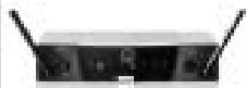
1 SR 40 FLEXX receiver
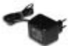
1 AC adapter
(see sticker on packaging)
1 Manual Supplement
sheet
2.3 Optional Accessories
- Check that the packaging contains all of the items listed for your system. Should any item be missing, please contact your AKG dealer.
2.4 SR 40 FLEXX Receiver
- For optional accessories, refer to the current AKG catalog or folder, or visit www.akg.com. Your dealer will be glad to help.
*Ask your dealer about usable frequency bands for WMS 40 FLEXX systems with more than three channels.
The SR 40 FLEXX is a stationary diversity receiver for use with all WMS 40 FLEXX and Microtools Series transmitters. It features a half-rack case for mounting in a 19" rack.
Operating in the 660 MHz to 865 MHz UHF range, the SR 40 FLEXX provides three selectable, quartz stabilized carrier frequencies within the 3-MHz-wide frequency band for which you ordered your WMS 40 FLEXX. This allows you to select a different frequency if one of the three frequencies does not provide adequate signal quality. The frequencies have been factory preset to make sure you can set up a multichannel system* with up to three channels with three kits operating in the same frequency band. Using a suitable combination of kits operating in different frequency bands you can even use up to nine channels simultaneously.
The SR 40 FLEXX is a diversity receiver and uses two antennas in order to receive the transmitter signal at two different spots. The diversity electronics will automatically activate the antenna that delivers the better signal.
An adjustable squelch will mute the receiver if the received signal is too weak so the related noise or the self-noise of the receiver will not become audible when the transmitter is switched OFF.
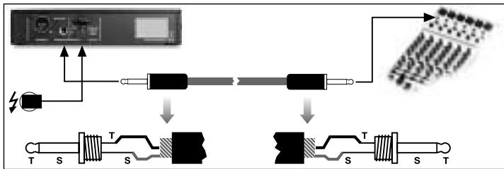
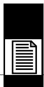
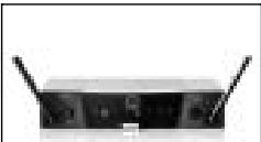
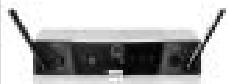
2.4.1 Front Panel Controls
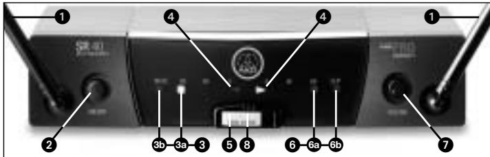
Fig. 1: Front panel controls on SR 40 FLEXX receiver. Refer to fig. 1.
1 Antennas: Fixed-length UHF antennas permanently mounted on the front panel. The diversity circuit will automatically activate the antenna that provides the better signal.
2 ON/OFF: On/off pushbutton switch. If the DIVERSITY LEDs A and B flash alternately and the RF MUTE LED is lit constantly, the receiver is ON but receives no signal. If the RF OK, AF OK, and only one of the two DIVERSITY LEDs are lit, the receiver is ON and receives signal.
When you switch the receiver OFF, all LEDs will extinguish.
3 RF LEDs: These LEDs indicate the quality of the received RF signal.
2 Description

Refer to fig. 1 on page 14.
3a OK (green): This LED is lit to indicate that an RF signal of adequate strength is being received.
3b MUTE (red): This LED is lit to indicate that no signal is being received or the squelch is active. In either case, the audio output will be muted automatically.
4 DIVERSITY LEDs A and B: Indicate which of the two receiving antennas is active at any time.
5 Color code: The color indicates the carrier frequency band of the receiver. Transmitters and receivers tuned to the same frequency band are marked with the same color. Refer to the Manual Supplement sheet for a color code table.
6 AF LEDs: Indicate the received audio level:
6a OK (green): -30 dB to +3 dB
6b CLIP (red): >3 dB. This LED illuminates to indicate the audio level of the received signal is overloading the receiver's audio section.
The green AF OK LED being lit and the red AF CLIP LED flashing occasionally indicate optimum modulation.
If none of the LEDs is lit, the gain setting on the transmitter is too low.
7 VOLUME: This rotary control adjusts the receiver's output level from microphone to line level for matching to the input sensitivity of your mixer or amplifier. The control range is 26 dB.
8 Frequency selector: This slide switch tunes the receiver to one of three different carrier frequencies within the receiver's carrier frequency band.
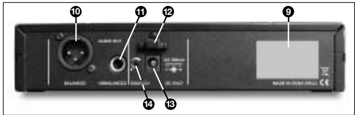
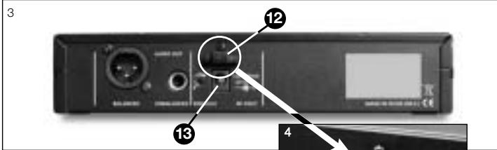
Fig.2: Rear panel of SR 40 FLEXX receiver.
2.4.2 Rear Panel
Refer to fig. 2.
9 Carrier frequency label: A label indicating the name of the carrier frequency band and the three carrier frequencies of your receiver is affixed to the rear panel of the receiver.
10 AUDIO OUT/BALANCED: Balanced 3-pin XLR audio output for connecting to, e.g., a microphone input on the mixing console.
11 AUDIO OUT/UNBALANCED: Unbalanced audio output on a 1/4" TS jack for connecting to, e.g., a guitar amplifier.
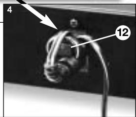
12 Strain relief for the feeder cable of the supplied AC adapter.
13 DC ONLY: Input connector for the supplied AC adapter.
14 SQUELCH: The squelch circuit switches the receiver off if the received signal is too weak, in order to suppress the related noise or the residual noise of the receiver while the transmitter is off. Set the SQUELCH control to minimum before first switching the receiver on.

Important!
3.1 Positioning the Receiver
3 Setting up
- Before setting up your WMS 40 FLEXX, make sure to set the frequency selectors on the transmitter and receiver to the same frequency (1, 2, or 3). If the transmitter and receiver are tuned to different frequencies, no signal will be transmitted!
-
Never use the two audio outputs (BALANCED and UNBALANCED) simultaneously! This may cause signal loss or increased noise.
-
You can either use the receiver freestanding or mount it in a 19" rack using the optional RMU 40 PRO rack mounting kit. For instructions on how to rack mount the receiver, refer to the RMU 40 PRO manual.
- Reflections off metal parts, walls, ceilings, etc. or the shadow effects of musicians and other people may weaken or cancel the direct transmitter signal.
For best results, place the receiver as follows:
- Place the receiver near the performance area (stage). Make sure, though, that the transmitter will never get any closer to the receiver than 10 ft (3 m). Optimum separation is 16 ft. (5 m).
- Check that you can see the receiver from where you will be using the transmitter.
- Place the receiver at least 5 ft. (1.5 m) away from any big metal objects, walls, scaffolding, ceilings, etc.
3.2 Connecting the Receiver to a Balanced Input
Fig. 3: Connecting the receiver to a balanced mixer input.
Refer to fig. 3.

- Use a standard XLR cable to connect the BALANCED output (10) on the receiver rear panel to a balanced XLR microphone input on the mixer.
- Turn the VOLUME control (7) on the receiver front panel all the way CCW to set the receiver output to microphone level.
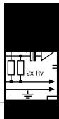
3.3 Connecting the Receiver to an Unbalanced Input
Fig. 4: Connecting the receiver to an unbalanced mixer input.
Refer to fig. 4.
- Use a standard 1/4" jack cable to connect the UNBALANCED jack (11) on the receiver rear panel to an unbalanced 1/4" line input on the mixer.
- Turn the VOLUME control (7) on the receiver front panel all the way CW to set the receiver output to line level.
Important!

- To avoid hum interference, do not use audio cables that are longer than 10 feet (3 m)!
3 Setting up
3.4 Connecting
the Receiver to Power

Fig. 5: Connecting to power.
Refer to fig. 5.
-
Check that the AC mains voltage stated on the included power supply is identical to the AC mains voltage available where you will use your system. Using the power supply with a different AC voltage may cause damage to the unit.
-
Point the antennas (1) upward.
- Plug the feeder cable on the included power supply into the DC ONLY socket (13) on the receiver.
- Bend part of the feeder cable into a small bight, pass the bight through the strain relief (12) from above, and slip the bight over the hook on the strain relief (12). Tighten the cable.
- Plug the AC adapter into a convenient power outlet.
- To switch power to the receiver on, press ON/OFF (2). To switch power to the receiver off, press ON/OFF (2) again.
Your receiver can only receive the transmitter signal if
a) the transmitter and receiver operate within the same frequency band; and
b) the transmitter and receiver are set to the same frequency within this frequency band.
3.5 Setting Frequencies
3 Setting up
- Check that the carrier frequency (frequencies) of the transmitter is (are) identical to the receiving frequencies of your SR 40 FLEXX. The carrier frequency (frequencies) of the transmitter and the receiving frequencies of the receiver are indicated in MHz on the respective frequency stickers and in the respective Manual Supplements.
-
HT 40 FLEXX and PT 40 FLEXX:
-
Set the frequency selector on the transmitter and the frequency selector (8) on the receiver to the same positions (1 - 1, 2 - 2, or 3 - 3).
HT 40 PRO, PT 40 PRO, Microtools:
- Switch power to the transmitter and receiver ON.
-
If the RF MUTE LED (3b) on the receiver is lit, set the frequency selector (8) on the receiver to a position where RF MUTE (3b) goes out and the RF OK LED (3a) comes on.
-
Move the transmitter around the area where you will use the system to check the area for "dead spots", i.e., places where the field strength seems to drop and reception deteriorates.
If you find any dead spots, try to eliminate them by repositioning the receiver. If this does not help, avoid the dead spots. - The RF OK LED (3a) on the receiver going out means no signal is being received or the squelch is active.
Switch the transmitter on, move closer to the receiver, or set the squelch threshold to the point that the green RF OK LED (3a) will be lit. - If the received signal is noisy, set the squelch threshold to a level where the noise will stop.

- Never set the squelch threshold any higher than absolutely necessary. The higher the squelch threshold (-70dBm = ., -100dBm = .) , the lower the sensitivity of the receiver and thus the usable range between transmitter and receiver.
The spacing between the three frequencies of each WMS 40 FLEXX transmitter and receiver is wide enough for operating three radio channels simultaneously within the same frequency band with no mutual interference.
-
For systems with up to nine channels you will need WMS 40 FLEXX kits in up to three different frequency bands. Please ask your dealer which frequency bands are suited for multichannel use and approved for the place where you will use the system. Perform steps 1 through 6 for each frequency band separately.
-
Switch power to all transmitters and receivers off.
- Set the frequency selectors on the transmitter and receiver for channel 1 to "1".
- Set the frequency selectors on the transmitter and receiver for channel 2 to "2".
- Set the frequency selectors on the transmitter and receiver for channel 3 to "3".
- Set up the transmitter and receiver for channel 1.
- Repeat steps 1 through 5 for channels 2 and 3.

- Do not operate two or more wireless channels on the same frequency at the same time and location. This would cause unwanted noise due to radio interference.
- Prior to changing a carrier frequency, be sure to switch the transmitter off. To activate the new carrier frequency, switch the transmitter back on.
4 Cleaning

- Use a soft cloth moistened with water to clean the receiver surfaces.
5 Troubleshooting

| Problem | Possible Cause | Remedy |
| No sound. | 1. AC adapter is not connected to receiver and/or power outlet. 2. Receiver is OFF. 3. Receiver is not connected to mixer or amplifier. 4. VOLUME control on receiver is at zero. 5. Microphone or instrument is not connected to bodypack transmitter. 6. Transmitter is tuned to different frequency than receiver. 7. Transmitter on/off switch is at "OFF" or "MUTE". 8. Transmitter battery(ies) is(are) not inserted properly. 9. Transmitter battery(ies) dead. 10. Transmitter is too far away from receiver or squelch threshold setting is too high. 11. Obstructions between transmitter and receiver. 12. Receiver is invisible from transmitter location. 13. Receiver is too close to metal objects. | 1. Connect AC adapter to receiver and/or power outlet. 2. Push ON/OFF switch to switch receiver ON. 3. Connect receiver output to mixer or amplifier input. 4. Turn up VOLUME control. 5. Connect microphone or instrument to audio input on bodypack. 6. Tune transmitter and receiver to same frequency / use transmitter with compatible frequency. 7. Set transmitter on/off switch to "ON". 8. Insert battery(ies) conforming to "+" and "-" marks. 9. Replace battery(ies). 10. Move closer to receiver or reduce squelch threshold setting. 11. Remove obstructions. 12. Avoid spots where you cannot see receiver. 13. Move receiver away from or remove interfering objects. |
| Noise, crackling, unwanted signals. | 1. Antenna location. 2. Interference from other wireless systems, TV, radio, CB radios, or defective electrical appliances or installations. | 1. Relocate receiver. 2. Switch off interference sources or defective appliances; switch transmitter and receiver to different frequency / use transmitter and receiver operating in a different frequency band; have electrical installation checked. |
| Distortion. | 1. GAIN control is set too high or too low. | 1. Handheld transmitter: Set GAIN to alternative position. Bodypack transmitter: Turn GAIN control down or up just enough to stop the distortion. |
5 Troubleshooting
| Problem | Possible Cause | Remedy |
| 2. Interference from other wireless systems, TV, radio, CB radios, or defective electrical appliances or installations. | 2. Switch off interference sources or defective appliances; switch transmitter and receiver to different frequency / use transmitter and receiver operating in a different frequency band; have electrical installation checked. | |
| Momentary loss of sound ("dropouts") at some locations within performance area. | Antenna location. | Relocate receiver. If dead spots persist, mark and avoid them. |

6 Specifications
| Receiving frequency | 660 to 865 MHz |
| Modulation | FM |
| Audio bandwidth | 35 Hz to 20 kHz |
| T.H.D. at 1 kHz | typ. 0.8% |
| Compander | Yes |
| Signal/noise ratio | typ. 110 dB(A) |
| Current consumption | 115 mA/12 V |
| Power requirement | 120/230 VAC, 50/60 Hz |
| Squelch threshold | -100 dBm to -70 dBm, adjustable |
| Audio output | bal. XLR and unbal. 1/4" jack: adjustable from mic to line level. Output level at rated deviation: 500 mV rms |
| Size | 200 x 190 x 44 mm (7.8 x 7.4 x 1.7 in.) |
| Net weight | 665 g (1.5 lbs.) |
This product conforms to the standards listed in the Declaration of Conformity. To order a free copy of the Declaration of Conformity, visit http://www.akg.com or contact sales@akg.com.

Sommaire
Page
1 Receptor SR 40 Flexx
1 Supplemento ("Manual Supplement")
1 Receptor SR 40 FLEXX
5 Resolver problemas

5 Resolver problemas
For other products and distributors worldwide visit www.akg.com


ROHS OK
H A Harman International Company
Technische Änderungen vorbehalten. Specifications subject to change without notice. Ces caractéristiques sont susceptibles de modifications. Ci riserviamo il diritto di effettare modifiche tecniche. Nos reservamos el dato de introduir modificaciones(ECNCAS). Especificações sujeitas a mudanças sem uso prévio.
Printed in China (P.R.C.)
01/08/9100 U 12660

- FCC Statement
- Safety and Environment
- Environment
- Introduction
- Description
- Packing List
- Optional Accessories
- SR 40 FLEXX Receiver
- Front Panel Controls
- Rear Panel
- Positioning the Receiver
- Setting up
- Connecting the Receiver to a Balanced Input
- Connecting the Receiver to an Unbalanced Input
- Connecting
- the Receiver to Power
- Setting Frequencies
- HT 40 PRO, PT 40 PRO, Microtools:
- Cleaning
- Troubleshooting
- Specifications
- Sommaire
- Resolver problemas
- H A Harman International Company
Brand : AKG
Model : SR 40 FLEXX
Category : Wireless Microphone System