
HEARO 999 AUDIOSPHERE PROCESSOR - Audio processor AKG - Free user manual and instructions
Find the device manual for free HEARO 999 AUDIOSPHERE PROCESSOR AKG in PDF.
User questions about HEARO 999 AUDIOSPHERE PROCESSOR AKG
0 question about this device. Answer the ones you know or ask your own.
Ask a new question about this device
Download the instructions for your Audio processor in PDF format for free! Find your manual HEARO 999 AUDIOSPHERE PROCESSOR - AKG and take your electronic device back in hand. On this page are published all the documents necessary for the use of your device. HEARO 999 AUDIOSPHERE PROCESSOR by AKG.
USER MANUAL HEARO 999 AUDIOSPHERE PROCESSOR AKG
HEARO 999 AUDIOSPHERE DIGITAL PROCESSOR
text_image
H-RS40 959 AUDIOSPHERE AVOC VOUT ACB 1000 MHz 1000 MHz 1000 MHz 1000 MHz 1000 MHz 1000 MHz 1000 MHz 1000 MHz 1000 MHz 1000 MHz 1000 MHz 1000 MHz 1000 MHz 1000 MHz 1000 MHz 1000 MHz 1000 MHz 10,000 MHz 1,500 MHz 2,500 MHz 3,500 MHz 4,500 MHz 5,500 MHz 6,500 MHz 7,500 MHz 8,500 MHz 9,500 MHz 10,500 MHz 11,500 MHz 12,500 MHz 13,500 MHz 14,500 MHz 15,500 MHz 16,500 MHz 17,500 MHz 18,500 MHz 19,500 MHz 20,500 MHz 21,500 MHz 22,500 MHz 23,500 MHz 24,500 MHz 25,500 MHz 26,500 MHz 27,500 MHz 28,500 MHz 29,500 MHz 30,500 MHz 31,500 MHz 32,500 MHz 33,500 MHz 34,500 MHz 35,500 MHz 36,500 MHz 37,500 MHz 38,500 MHz 39,500 MHz 40,500 MHz 41,500 MHz 42,500 MHz 43,500 MHz 44,500 MHz 45,500 MHz 46,500 MHz 47,500 MHz 48,500 MHz 49,500 MHz 50,500 MHzH A Haman International Company
AKG Acoustics GmbH
Lemböckgasse 21–25, P.O.B. 158, A-1230 Wien/ÖSTERREICH, Tel: (43 1) 86 654-0", Fax: (43 1) 86 654-516, http://www.akg-acoustics.com, e-mail: sales@akg-acoustics.com
AKG Acoustics, Harman Pro GmbH
Bodenseestraße 228, D-81243 München/DEUTSCHLAND, Tel: (089) 87 16-0, Fax: (089) 87 16-200, http://www.akg-acoustics.de, e-mail: info@akg-acoustics.de
For other products and distributors worldwide see our website: http://www.akg-acoustics.com
User Instructions ..... p. 14
Please read the manual before using the equipment!
text_image
Diagram illustrating a human profile with labeled indicators for ECG, W, and W̃ symbolstext_image
Diagram illustrating sound pressure or vibration effects on a human head with three circular indicators and directional arrows indicating sound flow.2.6 Dolby Surround Pro-Logic Decoder
1 Safety and Environment 14
2 Description....15
2.1 Introduction 15
2.2 Unpacking 15
2.3 Optional Accessories 15
2.4 General Description 15
2.5 IVA Individual Virtual Acoustics....15
2.6 Dolby Surround Pro-Logic Decoder 16
2.7 Dolby Digital Decoder....16
2.8 VMAx Processor....16
2.9 Controls....17
3 Audio and Power Connections 19
3.1 Connecting to Audio Sources....19
3.2 Audio Outputs 19
3.3 Connecting to Power 19
3.4 Rack Mounting a Single Unit 20
3.5 Rack Mounting Two Units Sice by Side 20
4 Operating Notes 21
4.1 Important Notes 21
4.2 Setting Up the System 21
4.3 Using Headphones....21
4.4 Using Loudspeakers....22
4.5 Test Signals for Choosing Ear Matching Curves 22
5 Cleaning 23
6 Troubleshooting 24
7 Specifications....25
8 Warranty Conditions....25

1 Safety and Environment
1.1 Operate the equipment with the supplied 12 VDC, 800 mA AC adapter only. Check that the AC voltage stated on the AC adapter is the same as that available in your country. Using the transmitter with a different AC adapter voids the warranty.
1.2 Never try to open the equipment's case. Refer servicing to qualified service personnel only.
1.3 Never place the equipment near heat sources such as radiators or electric heaters or expose it to direct sunlight, excessive dust, humidity, rain, temperatures below freezing, or impacts. Never use petroleum-based cleaners or paint thinners to clean the equipment.
1.4 If you do not use your equipment for an extended period of time (e.g., when traveling), dis-
1.5 connect the AC adapter from the AC outlet.
Also refer to section 4.1 Important Notes.
1.6 When scrapping the equipment, separate the case, circuit boards, and cables, and dispose
1.7 of all components in accordance with local waste disposal rules.
FCC Statement: This equipment has been tested and found to comply with the limits for a Class B digital device, pursuant to Part 15 of the FCC Rules. These limits are designed to provide reasonable protection against harmful interference in a residential installation. This equipment generates, uses and can radiate radio frequency energy and, if not installed and used in accordance with the instructions, may cause harmful interference to radio communications. However, there is no guarantee that interference will not occur in a particular installation. If this equipment does cause harmful interference to radio or television reception, which can be determined by turning the equipment off and on, the user is encouraged to try to correct the interference by one or more of the following measures:
- Reorient or relocate the receiving antenna.
- Increase the separation between the equipment and receiver.
- Connect the equipment into an outlet on a circuit different from that to which the receiver is connected.
- Consult the dealer or an experienced radio/TV technician for help
Dear Customer:
Thank you for purchasing an AKG product.
In order to make optimum use of the benefits of your HEARO 999 AUDIOSPHERE, please take a few minutes to read the instructions below carefully before operating the equipment. Please keep the manual for future reference.
If you have any questions beyond the scope of this Manual, visit our website at:
http://www.akg-acoustics.com/english/headphones/hearo999/faqs.htm
Your HEARO 999 AUDIOSPHERE comprises the following components:
1 HEARO 999 AUDIOSPHERE with integrated surround processors and UHF transmitter
2 stereo connecting cables for interfacing your HEARO 999 AUDIOSPHERE with your audio, video or TV system
1 AC adapter
1 fiber optical cable for connecting your HEARO 999 AUDIOSPHERE to an optical digital output
Check the packaging. If any of the above items is missing, contact your AKG dealer immediately.
RMU 60 rack mount kit for one or two HEARO 999 AUDIOSPHERE units
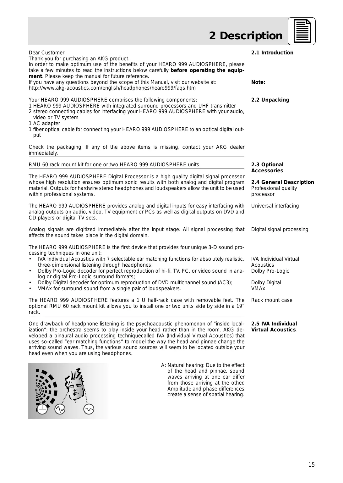
The HEARO 999 AUDIOSPHERE Digital Processor is a high quality digital signal processor whose high resolution ensures optimum sonic results with both analog and digital program material. Outputs for hardwire stereo headphones and loudspeakers allow the unit to be used within professional systems.
The HEARO 999 AUDIOSPHERE provides analog and digital inputs for easy interfacing with analog outputs on audio, video, TV equipment or PCs as well as digital outputs on DVD and CD players or digital TV sets.
Analog signals are digitized immediately after the input stage. All signal processing that affects the sound takes place in the digital domain.
The HEARO 999 AUDIOSPHERE is the first device that provides four unique 3-D sound processing techniques in one unit:
- IVA Individual Acoustics with 7 selectable ear matching functions for absolutely realistic, three-dimensional listening through headphones;
- Dolby Pro-Logic decoder for perfect reproduction of hi-fi, TV, PC, or video sound in analog or digital Pro-Logic surround formats;
• Dolby Digital decoder for optimum reproduction of DVD multichannel sound (AC3);
• VMAx for surround sound from a single pair of loudspeakers.
The HEARO 999 AUDIOSPHERE features a 1 U half-rack case with removable feet. The optional RMU 60 rack mount kit allows you to install one or two units side by side in a 19" rack.
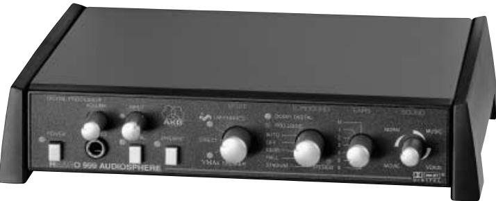
One drawback of headphone listening is the psychoacoustic phenomenon of "inside localization": the orchestra seems to play inside your head rather than in the room. AKG developed a binaural audio processing technique called IVA (Individual Virtual Acoustics) that uses so-called "ear matching functions" to model the way the head and pinnae change the arriving sound waves. Thus, the various sound sources will seem to be located outside your head even when you are using headphones.
2.1 Introduction
Note:
2.2 Unpacking
2.3 Optional
Accessories
2.4 General Description
Professional quality processor
Universal interfacing
Digital signal processing
IVA Individual Virtual
Acoustics
Dolby Pro-Logic
Dolby Digital
VMAX
Rack mount case
2.5 IVA Individual
Virtual Acoustics
text_image
Diagram illustrating a human head with concentric circular patterns and three labeled icons below: EKG, WTR, and WNT.A: Natural hearing: Due to the effect of the head and pinnae, sound waves arriving at one ear differ from those arriving at the other. Amplitude and phase differences create a sense of spatial hearing.
text_image
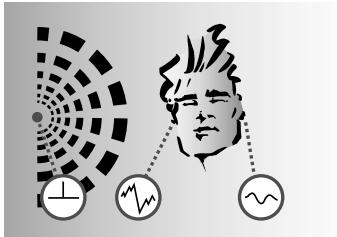
Diagram illustrating sound pressure or vibration effects on a human head with three circular indicators and directional arrows indicating sound flow.B: Listening through headphones: Amplitude and phase differences are eliminated. Sound sources are localized inside the head rather than in the room.
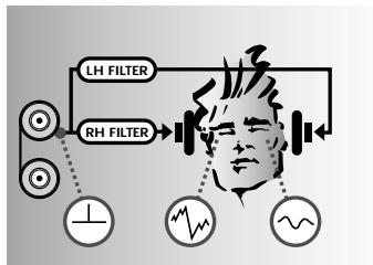
flowchart
graph TD
    A["LH FILTER"] --> B["Human Head"]
    C["RH FILTER"] --> B
    B --> D["Waveform Indicator"]
    D --> E["Output Signal"]
    style B fill:#f9f,stroke:#333
    style D fill:#ccf,stroke:#333
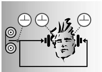
C: Listening through headphones with IVA processing: The ear matching function modifies the audio signals at the ears to resemble diagram A. This restores natural, spatial hearing.
2.6 Dolby Surround Pro-Logic Decoder
The Dolby Surround Pro-Logic decoder integrated in the HEARO 999 AUDIOSPHERE derives a center and a surround channel from a Pro-Logic encoded stereo signal. The IVA processor converts these signals to a binaural format equivalent to that reproduced by four high quality loudspeakers (3 front, 1 rear speaker). This lets you enjoy the 360^ listening experience of Dolby Surround even through headphones.
2.7 Dolby Digital Decoder
Also integrated in the HEARO 999 AUDIOSPHERE, the Dolby Digital decoder processes digital multichannel signals in Dolby Digital format for perfect reproduction via headphones. Dolby Digital provides even better channel separation and five loudspeaker channels. The IVA processor converts these signals to a binaural format equivalent to that reproduced by five high quality loudspeakers (3 front, 2 rear speakers).
2.8 VMAx Processor
The VMAx processor enables a single pair of loudspeakers to provide surround sound. Similar to IVA, VMAx processing derives three-dimensional sound from analog or digital input signals. VMAx will simulate the appropriate loudspeakers for Dolby Pro-Logic and Dolby Digital encoded input signals. VMAx also allows you to increase the virtual distance between closely spaced stereo loudspeakers (e.g., speakers placed next to a computer monitor). The processed signal is available at the analog audio output so you can use a standard stereo amplifier to reproduce the VMAx signal.
text_image
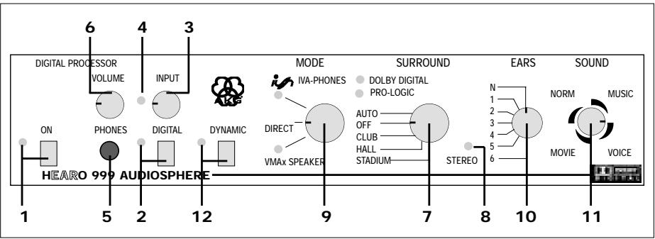
DIGITAL PROCESSOR VOLUME 6 4 3 INPUT DIGITAL ON PHONES 12 DYNAMIC MODE IVA-PHONES DIRECT VMAX SPEAKER SURROUND DOLBY DIGITAL PRO-LOGIC AUTO OFF CLUB HALL STADIUM STEREO EARS N 1 2 3 4 5 6 SOUND NORM MUSIC MOVI E VOICE 1 5 2 HEARO 999 AUDIOSPHERE 7 8 10 112.9 Controls
2.9.1 Front Panel
- ON: This pushbutton switches the unit on and off. The green LED next to the ON switch lights to indicate the unit is ON.
- DIGITAL: This pushbutton switch toggles between the analog and digital inputs. The green LED next to the DIGITAL switch lights to indicate the digital input has been selected.
- INPUT: This rotary control sets the level at the audio output.
Selecting the digital input disables the INPUT control.
- INPUT LED: This bi-color LED indicates the signal level at the input to the audio circuitry: flickering/lighting green indicates optimum level range, red indicates overload.
- PHONES: 1/4" stereo jack for connecting a pair of hardwire stereo headphones.
- VOLUME: This rotary control sets the volume of the headphones connected to the PHONES jack (5).
- SURROUND: This five-step rotary switch is located in the signal path between the input stage and the MODE switch. It switches the Dolby decoders on and off or adds one of three different reverb programs to normal stereo signals. The output signal of the SURROUND selector passes through the MODE switch and on to the IVA or VMAx processor or directly to the output.
AUTO: This mode automatically activates the Dolby Pro-Logic or Dolby Digital decoder depending on whether a Pro-Logic or Dolby Digital signal is present at the input. One green LED each will light to indicate which decoder is currently active.
If a normal stereo signal is present at the input, we recommend that you set the SURROUND selector to "OFF" in order to avoid undesired sonic results.
OFF: Both Dolby decoders are out of circuit and the input signal passes to the MODE selector (9) unchanged. The DOLBY DIGITAL and the PRO-LOGIC LEDs will extinguish.
CLUB, HALL, STADIUM: Acoustic simulations of three different venues of different sizes.
- STEREO: This green LED indicates the following modes:
| Stereo signal at the input and SURROUND selector (7) in “OFF” position: | STEREO LED on |
| SURROUND selector (7) in “CLUB”, “HALL”, OR “STADIUM” position: | |
| SURROUND selector (7) in “AUTO” position: | STEREO LED off |
| MODE selector (9) in “DIRECT” position: | |
| MODE selector (9) in “IVA-PHONES” or “VMAx” position and SURROUND selector (7) in “AUTO” position: |
Note:
- MODE: This three-step rotary switch selects the following modes:
IVA-PHONES: The IVA processor is active and affects the signal at the PHONES and LINE outputs. In this mode, the green LED below the IVA-PHONES label will be illuminated.
DIRECT: In this mode, all signal processors are out of circuit and all controls and indicators to the right of the MODE selector are disabled. You will hear the unchanged stereo input signal in the hardwire and wireless headphones and the loudspeakers you may have connected to the HEARO 999 AUDIOSPHERE. The IVA-PHONES and VMAx LEDs extinguish.
A Dolby Digital encoded signal present at the input will be automatically mixed down to a Pro-Logic encoded stereo signal.
VMAx: The VMAx processor derives a 3-D signal for loudspeaker reproduction. In VMAx mode, the green LED above the VMAx label will be illuminated.
Important Note: In all modes, the same signal will be available at all outputs (PHONES and LINE OUT).
- EARS: The shape of the outer ear changes the waveform of impinging sound in a unique way that differs from person to person. Using headphones defeats these outer ear transfer functions because the sound sources are located immediately in front of the ears. The result is unnatural sound.
In order to provide the most realistic headphone reproduction possible, AKG measured many outer ear transfer functions and electronically modeled seven representative "ear curves".
In IVA-PHONES mode, the EARS selector offers a choice of one standard ear curve ("N") and six other ear curves for you to select the one that sounds the most natural to you. In DIRECT and VMAx modes, the EARS selector is disabled.
- SOUND: In IVA-PHONES mode, this 12-step rotary switch lets you select four different sound programs, each with three speaker spreader settings (close, medium, or wide virtual stereo spread):
NORM: Basic sound program for all types of program material.
MUSIC: Linear response for a neutral sound rich in detail.
VOICE: This sound program has been optimized for intelligibility of speech and is therefore recommended for radio and TV programs with a high proportion of speech, or for monitoring during speech and vocal recording sessions in the studio.
MOVIE: Simulates the typical sound of theater speakers and is therefore recommended for videos and DVD movies in Dolby Surround or Dolby Digital formats.
Note:
In VMAx mode, only the speaker spreader function without the sound programs will be available.
- DYNAMIC: The dynamic range (the difference between the loudest and softest passages) of Dolby Digital encoded input signals may sometimes be so great that soft dialogs may become unintelligible.
With the DYNAMIC switch OUT, the dynamic range is being reduced. This means that very soft passages will automatically be raised in level while very loud passages are attenuated. The green LED next to the switch remains dark.
With the DYNAMIC switch IN, the full dynamic range of the input signal is preserved and the green LED next to the switch illuminates.
2.9.2 Rear Panel
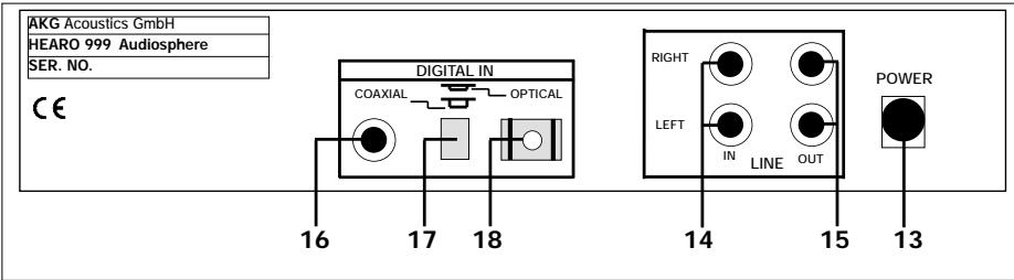
text_image
AKG Acoustics GmbH HEARO 999 Audiosphere SER. NO. CE DIGITAL IN COAXIAL OPTICAL RIGHT LEFT IN LINE OUT POWER 16 17 18 14 15 13-
POWER: Input jack for the AC adapter.
-
LINE IN LEFT/RIGHT: RCA audio input jacks for analog stereo or Pro-Logic encoded signals.
-
LINE OUT LEFT/RIGHT: Analog RCA audio output jacks. The output level depends on the setting of the INPUT control (3). The VOLUME control (6) does not affect the output level.
-
COAXIAL: RCA input jack for an optional coaxial cable for interfacing with a digital audio source with a coaxial output.
-
DIGITAL IN: Pushbutton switch that activates either the coaxial or the optical digital input.
-
OPTICAL: Input connector for the supplied fiber optical cable for interfacing with a digital audio source with an optical output.
3 Audio and Power Connections
You may use the HEARO 999 AUDIOSPHERE either free-standing or install it in a 19" rack using the optional RMU 60 rack mount kit.
You can connect the HEARO 999 AUDIOSPHERE to any analog headphones output (mini jack or 1/4" jack), to the LINE or REC output of your amplifier, or to an optical or coaxial digital output.
When using an analog audio source, check that the DIGITAL switch (2) is OUT. When using a digital audio source, check that the DIGITAL switch (2) is IN.
- Before connecting the HEARO 999 AUDIOSPHERE to your audio source, switch power to your audio source OFF.
- Plug the red RCA connector (right channel) on the supplied RCA/jack cable into the red LINE IN RIGHT jack (14) and the white RCA connector (left channel) into the white LINE IN LEFT jack (14) on the HEARO rear panel.
- Connect the stereo mini jack plug on the RCA/jack cable to the headphones output of your audio source.
-
If the headphones output on your equipment is a 1/4" jack, plug the supplied mini jack to 1/4" adapter onto the mini jack. Connect the adapter jack to the headphones output.
-
Before connecting the transmitter to your audio source, switch power to the audio source OFF.
-
Use a stereo RCA cable (not supplied) to connect the white LINE OUT L or REC OUT L jack on your audio source to the white LINE IN LEFT jack (14) on the HEARO rear panel and the red LINE OUT R or REC OUT R jack to the red LINE IN RIGHT jack (14).
-
Switch power to your audio source OFF.
- Use an optional coaxial cable (mono RCA cable) to connect the coaxial output on your DVD or CD player, digital TV set, or other equipment to the COAXIAL jack (16) on the HEARO rear panel.
-
The coaxial input is active when the DIGITAL IN switch (17) is OUT. If the DIGITAL IN switch (17) is IN, push it once to activate the coaxial input.
-
Switch power to your audio source OFF.
- Use the supplied fiber optical cable to connect the optical output on your DVD or CD player, digital TV set, or other equipment to the OPTICAL jack (18) on the HEARO rear panel.
- The optical input is active when the DIGITAL IN switch (17) is IN. If the DIGITAL IN switch (17) is OUT, push it once to activate the optical input.
You can connect each digital input to a digital audio source and use the DIGITAL IN switch (17) to toggle between the two audio sources.
- Switch power to your audio source OFF.
- Use the supplied RCA cable to connect the white "TAPE IN", "AUX IN", or "PLAYBACK IN" jack on the amplifier to the white LINE OUT LEFT jack (15) and the red "TAPE IN", "AUX IN", or "PLAYBACK IN" jack on the amplifier to the red LINE OUT RIGHT jack (15) on the HEARO rear panel.
-
Refer to the operating manual of your amplifier for instructions on how to listen to and mute the signal at the TAPE", "AUX", or "PLAYBACK" input. On most amplifiers, you can push the "TAPE MONITOR" switch IN to listen to the processed signal and OUT to cut the processed signal.
-
Connect the stereo jack plug on your hardwire stereo headphones to the PHONES jack (5). You can use the VOLUME control (6) to set the volume of the headphones.
-
Connect the DC cable on the supplied AC adapter to the POWER jack (13) on the HEARO rear panel.
- Check that the AC voltage stated on the AC adapter is the same as that available where you will use the unit. If it is, connect the AC adapter to a convenient AC outlet.
Refer to sections 3.4, 3.5, and fig. 1.
3.1 Connecting to Audio Sources
Note:
3.1.1 Connecting to an Analog Headphones Output
Refer to the wiring diagram in fig. 2.
3.1.2 Connecting to an Analog LINE or REC Output
Refer to the wiring diagram in fig. 3.
3.1.3 Connecting to a Coaxial Digital Output
Refer to the wiring diagram in fig. 4.
3.1.4 Connecting to an Optical Digital Output
Refer to the wiring diagram in fig. 4.
Note:
3.2 Audio Outputs 3.2.1 LINE OUT
Refer to the wiring diagram in fig. 5.
3.2.2 PHONES
3.3 Connecting to Power
Refer to fig. 6.
3 Audio and Power Connections
3.4 Rack Mounting a Single Unit
Refer to fig. 1b.
Refer to fig. 1c.
Refer to fig. 1d.
Mounting Two s Side by Side
- Unscrew the two fixing screws on the bottom of each side panel support.
- Remove the two side panel supports.
- Place a clamping slide (19) on each rack ear (20), checking that the pegs on the clamping slides (19) engage in the fixing holes on the rack ears (20).
- Slide the clamping slides (19) and rack ears (20) into the fixing rails on both sides of the unit from rear to front.
- Tighten the two Phillips screws in the clamping slides (19) CW to fix the rack ears (20) on the unit.
- Use the supplied screws to fix the supplied blank (21) panel to the left or right rack ear (20).
-
Use the supplied installation screws to install the unit in the rack.
-
Unscrew the two fixing screws on the bottom of each side panel support.
- Remove the two side panel supports.
- Fix one rack ear (20) to the outside panel of each unit referring to steps 1 through 3 above.
- Insert a clamping slide (19) with no rack ear (20) into the fixing rails on the INSIDE PANEL of one unit.
- Insert the unit with the clamping slide (19) on its inside panel into the fixing rails on the inside panel of the other unit.
- Tighten the two Phillips screws in the inside clamping slide (19) CW to connect the two units.
- Use the supplied installation screws to install the units in the rack.
Before setting up your system, please remember the following points:
- Operating switches on or connecting the HEARO 999 AUDIOSPHERE to your audio source may cause clicks which at high volume settings may affect your hearing. Therefore, be sure to set the VOLUME control (6) on the HEARO to minimum before switching between different sources (tuner, turntable, CD player, etc.) or connecting the HEARO.
-
Listening over headphones at high volume levels, particularly over extended periods of time, may damage your hearing.
-
Switch ON the audio source to which the HEARO 999 AUDIOSPHERE is connected.
-
Push the ON switch (1) to switch the HEARO 999 AUDIOSPHERE ON.
-
Check whether the green DIGITAL LED (2) is illuminated. If the DIGITAL LED (2) is dark, the audio circuitry is connected to the LINE IN LEFT/RIGHT analog inputs (14).
- If the green DIGITAL LED (2) is illuminated, the audio circuitry is connected to the digital inputs. Push the DIGITAL switch (2) to activate the analog inputs. The DIGITAL LED (2) will extinguish.
-
Use the INPUT control (3) on the HEARO front panel to set the input level such that the INPUT LED (4) next to the INPUT control (3) will flicker green in step with the input signal or light green steadily, occasionally flashing red on extremely loud sounds. Turn the INPUT control (3) CCW just enough to stop the INPUT LED (4) flashing red.
-
Check whether the green DIGITAL LED (2) is illuminated. If the green DIGITAL LED (2) is illuminated, the audio circuitry is connected to the digital inputs.
- If the DIGITAL LED (2) is dark, push the DIGITAL switch (8) to activate the digital inputs. The DIGITAL LED (2) will illuminate.
- Check the setting of the DIGITAL IN switch (17). If you connected your digital audio source to the COAXIAL jack (16), make sure the DIGITAL IN switch (17) is OUT. If you connected your digital audio source to the OPTICAL jack (18), make sure the DIGITAL IN switch (17) is IN.
There is no need to set the input level for digital input signals. Therefore, the INPUT control (3) is disabled as soon as you push the DIGITAL switch (2) IN.
If you connect an audio source to each of the two digital inputs, you can use the DIGITAL IN switch (17) to toggle between the two audio sources. You can not, however, listen to both audio sources simultaneously.
- Connect the stereo jack plug on the cable of your stereo headphones to the PHONES jack (5).
- Use the VOLUME control (6) to set the volume of the headphones.
To listen to the unprocessed stereo signal,
-
Set the MODE selector (9) to "DIRECT". This deactivates all audio processors. The appropriate LEDs and the STEREO LED (8) will extinguish and the SURROUND (7), EARS (10), and SOUND (11) selectors are disabled.
-
Set the MODE selector (9) to "IVA-PHONES". The IVA processor is active and the IVA LED illuminates.
- Set the SURROUND selector (7) to "OFF". The STEREO LED (8) illuminates and you will hear the IVA processed stereo signal.
- Select the ear curve that works best for you. Begin by setting the EARS selector (10) to "N" for the standard ear curve. Try the other six ear curves to find the one that you feel provides the most natural sonic perspective. (You may find that you do not always prefer the same ear curve!)
- Use the SOUND selector (11) to select the optimum sound setting. Each of the four sound settings ("NORM", "MUSIC", "VOICE", AND "MOVIE") provides three "subsettings" ("close", "medium", "wide") that let you change the spacing of the loudspeakers simulated by IVA processing.
- If you wish to add a room simulation to the signal for a live concert type ambience, set the SURROUND selector (7) to "CLUB" (small venue), "HALL" (medium size concert hall), or "STADIUM".
Since room simulation requires highly complex computing operations, there will be a delay of approximately 1 second as you switch from one room simulation to another.
4.1 Important Notes
4.2 Setting Up the System
4.2.1 Analog Audio Sources
4.2.2 Digital Audio Sources
Note:
Note:
4.3 Using Headphones
4.3.1 Stereo Mode
4.3.2 Stereo + IVA Mode
Note:
4.3.3 Dolby Surround and Dolby Digital
- Set the MODE selector (9) to "IVA-PHONES".
- Set the SURROUND selector (7) to "AUTO".
The STEREO LED (8) will extinguish.
Dolby Surround Pro-Logic signals will automatically activate the Dolby Surround Pro-Logic decoder and cause the PRO LOGIC LED to illuminate.
Dolby Digital signals will automatically activate the Dolby Digital decoder and cause the DOLBY DIGITAL LED to illuminate instead of the PRO LOGIC LED.
The room simulations ("CLUB", "HALL", "STADIUM") are not available in this mode. (If you set the SURROUND selector (7) to "CLUB", "HALL", or "STADIUM" even though a Dolby Digital signal is present at the input, the output signal is automatically muted and the INPUT LED (4) begins to flash red.
- Select the ear curve that works best for you.
Begin by setting the EARS selector (10) to "N" for the standard ear curve. Try the other six ear curves to find the one that you feel provides the most natural sonic perspective. (You may find that you do not always prefer the same ear curve!)
- Use the SOUND selector (11) to select the optimum sound setting.
Each of the four sound settings ("NORM", "MUSIC", "VOICE", AND "MOVIE") provides three "subsettings" ("close", "medium", "wide") that let you change the spacing of the loudspeakers simulated by IVA processing.
4.4 Using Loudspeakers
For connections refer to section 3.2.1 and fig. 5
To increase the virtual distance (“stereo spread”) between two closely spaced loudspeakers (e.g., computer speakers, near-field monitors),
For base angle, see fig. 7.
-
Set the MODE selector (9) to "VMAx". The VMAx LED will illuminate.
-
Set the SURROUND selector (7) to "OFF" for straight stereo mode or to "CLUB", "HALL", or "STADIUM" for stereo reproduction with room simulation. The STEREO LED will illuminate.
-
Set the SOUND selector (11) to "close" (<10°), "medium" (approx. 20°), or "wide" (>30°) depending on the base angle between your loudspeakers (A). The VMAx processor will simulate for each of these settings a virtual loudspeaker pair (B) with a base angle of 60°. Remember that in VMAx mode the SOUND selector (11) will only change the virtual stereo spread without changing sound programs.
4.4.1 Dolby Surround and Dolby Digital
To enjoy the full effect of Dolby Surround Pro-Logic or Dolby Digital encoded videos or TV programs through your existing stereo speaker pair,
- Set the MODE selector (9) to "VMAx". The VMAx LED will illuminate.
- Set the SURROUND selector (7) to "AUTO". The STEREO LED (8) will extinguish.
Dolby Surround Pro-Logic signals will automatically activate the Dolby Surround Pro-Logic decoder and cause the PRO LOGIC LED to illuminate.
Dolby Digital signals will automatically activate the Dolby Digital decoder and cause the DOLBY DIGITAL LED to illuminate instead of the PRO LOGIC LED.
The room simulations ("CLUB", "HALL", "STADIUM") are not available in this mode. (If you set the SURROUND selector (7) to "CLUB", "HALL", or "STADIUM" even though a Dolby Digital signal is present at the input, the output signal is automatically muted and the INPUT LED (4) begins to flash red.
Refer to fig. 8.
- Use the SOUND selector (11) to set the spacing of the simulated loudspeakers. You have a choice of three settings: "close", "medium", "wide".
Remember that in VMAx mode the SOUND selector (11) will only change the virtual stereo spread without changing sound programs.
4.5 Test Signals for Choosing Ear Matching Curves
If you want to adjust your HEARO 999 AUDIOSPHERE to your hearing with extra precision, visit http://www.akg-acoustics.com/english/headphones/Hearo999/ear-func.htm and download two specific test signals in WAV or MP3 format. Use the first signal, "Applause", to make a shortlist of the best ear matching curves. The second signal, "Acoustic Guitar Solo", is a pure mono signal (same level in the left and right channels) for choosing the winner.
Of course, you may as well use applause and a mono signal rich in transients (such as a solo piece for acoustic guitar) from an existing sound carrier.
Making the shortlist
- Set the MODE selector (9) to "DIRECT".
- Set the SOUND selector (11) to one of the three MUSIC positions.
- Start the "Applause" test signal.
- Set the MODE selector (9) to "IVA-PHONES" and the EARS selector (10) to "N". Set the MODE selector (9) to "DIRECT" to compare the sound of the processed test signal with the unprocessed test signal.
Repeat the comparison for each position of the EARS SELECTOR (10).
- Make a list of the three or four ear matching curves where you perceived the smallest change in sound compared to the unprocessed test signal, and which you felt sounded the most natural.
- Set the MODE selector (9) to "IVA-PHONES" and start the test signal "Acoustic Guitar Solo".
- Use the EARS selector (10) to compare the ear matching curves on your shortlist with one another.
- Make a list of those ear curves where the signal most closely approximated a "point source" (a sound source of zero width). For this test, it makes no difference whether you perceive the signal inside or outside your head.
- The ear matching curve that provides the closest approximation to a point source is the one most congruent with the transfer function of your ears. Your HEARO 999 AUDIO-SPHERE is now optimally adjusted to your ears for natural spatial hearing over headphones.
Choosing the Winner
5 Cleaning

We recommend to clean the surfaces of your HEARO 999 AUDIOSPHERE using a soft cloth moistened with water.
6 Troubleshooting
| Symptom | Possible Cause | Remedy |
| No sound | 1. AC adapter is not connected to HEARO and/or AC outlet.2. HEARO is OFF or not connected to audio source.3. Connected audio source is switched off.4. Wrong input selected.5. INPUT control is at zero.6. Volume control on audio source is set too low. | 1. Connect AC adapter to HEARO and/or AC outlet.2. Switch HEARO on or connect to audio source.3. Switch audio source on to feed signal to HEARO input.4. Activate the input that is actually used (see sections 4.3.1 and 4.3.2).5. Turn up INPUT control (refer to sections 4.2.1 and 4.2.2)6. Increase audio source volume to the point that HEARO switches on. |
| Mono sound | 1. Connected audio source operates in mono mode.2. HEARO is not correctly connected to audio source. | 1. Switch audio source to stereo mode.2. Check cable connection between HEARO and audio source. |
| Noise | 1. Audio level at HEARO input is too low.2. Input signal is noisy. | 1. Turn up audio source volume control and/or INPUT LEVEL control on HEARO.2. Check audio source. |
| Distorted sound | 1. Audio level at HEARO input is too high. | 1. Turn down audio source volume control and/or INPUT control on HEARO. |
| Intermodulation noise | 1. Electrical appliances with poor interference protection.2. Audio source or sound carrier defective. | 1. Switch off any “suspicious” appliances (if possible).2. Check audio source or sound carrier. |
| Overemphasized bass or treble | 1. Bass or treble control settings on audio source. | 1. Readjust bass or treble controls. |
| INPUT LED flashing red | 1. SURROUND selector at "CLUB", "HALL", or "STADIUM" although Dolby Digital signal is present at input. | 1. Set SURROUND selector to "AUTO". |
| Audio inputs: | analog: RCA connectors left/right, 20 bit convertersdigital: 1 x coaxial, 1 x optical (selectable) |
| Outputs: | analog audio output on left/right RCA jacks, with 20 bit converters |
| Digital signal processing: | 20/24 bit resolution |
| Audio bandwidth: | 20 Hz to 24 kHz |
| INPUT LED: | -18 dB to 0 dB: green; ≥0 dB: red |
| Power supply: | 12 VDC, 800 mA |
| Weight: | approx. 19.4 oz. (550 g) |
Manufactured under license from from Dolby Laboratories. "Dolby", "Pro Logic", and the double-D symbol are trademarks of Dolby Laboratories. Confidential unpublished works. © 1992-1997 Dolby Laboratories. All rights reserved.
VMAx is a registered trademark of Harman International.
8 Warranty Conditions
AKG warrants AKG products against evident defects in material and workmanship for a period of one year from the date of original purchase for use. This Warranty does not cover damage resulting from misuse or abuse, or lack of reasonable care, or inadequate repairs performed by unauthorized service centers. Performance of repairs or replacements under this Warranty is subject to submission of the sales slip. Shipment of defective items for repair under this Warranty will be at the customer's own risk and expense. This Warranty is valid for the original purchaser only.
Limited Warranty (valid in the United States only)
AKG warrants AKG products against evident defects in material and workmanship for a period of one year and agrees to repair or, at our option, replace any defective unit without charge for either parts or labor.
Important: This Warranty does not cover damage resulting from accident, misuse or abuse, lack of reasonable care, the affixing of any attachment not provided with the product, loss of parts, or connecting the product to any but the specified receptacles. This Warranty is void unless service or repairs are performed by an authorized service center. No responsibility is assumed for any special, incidental, or consequential damage. However, the limitation of any right or remedy shall not be effective where such is prohibited or restricted by law. Simply take or ship your AKG products prepaid to our service department. Be sure to include your sales slip as proof of purchase date. (We will not repair transit damage under the no-charge terms of this Warranty.)
Note: No other warranty, written or oral, is authorized by AKG Acoustics.
This Warranty gives you specific legal rights, and you may also have other rights which vary from state to state. Some states do not allow the exclusion or limitation of incidental or consequential damage or limitations on how long an implied warranty lasts, so the above exclusion and limitations may not apply to you.
page
Cher client/chère cliente,
text_image
Diagram illustrating a person's face with concentric circular patterns and three labeled icons: a circle with a plus sign, a jagged line graph, and a wavy line.text_image
Diagram illustrating human head with three circular indicators and directional arrows, possibly indicating physiological or behavioral changes.http://www.akg-acoustics.com/english/headphones/Hearo999/ear-func.htm.
text_image
Diagram illustrating a human head profile with concentric circles and three labeled icons: standard, waveform, and wavy line.text_image
Diagram illustrating human head with three circular indicators and directional arrows, possibly indicating physiological or behavioral changes.2.6 Decoder Dolby Surround Pro-Logic
http://www.akg-acoustics.com/english/headphones/Hearo999/ear-func.htm,
text_image
Diagram illustrating a human profile with concentric circles and three labeled icons: a cross, a heartbeat waveform, and a wavy line.text_image
Diagram illustrating human head with three circular indicators and directional arrows, possibly indicating physiological or behavioral changes.2.6 Dolby Surround Pro-Logic Decoder
6 Resolver problemas 72
7 Dados técnicos 73