USER MANUAL B&W ASW300 B&W
Limited Warranty............2
Owner's Manual. 2
François
Garantie limitée.5
Ooyniec Xpnoewc....40
Pycckn
OrpaHnueHna
rapaHTnA. 45
PykoBoCTBO nO
3Kcnpnyatau..45
Norsk
Tidsbegrenset
garanti. 50
Bruksanvising .50
Svenska
Begransad garanti.....51
Bruksanvising .51
Suomi
Takuuehdot. 52
This product has been designed and manufactured to the highest quality standards. However, if something does go wrong with this product, B&W Loudspeakers and its national distributors warrant free of charge labour (exclusion may apply) and replacement parts in any country served by an official B&W distributor.
This limited warranty is valid for a period of five years from the date of purchase or two years for electronics including amplified loudspeakers.
Terms and Conditions
1 The warranty is limited to the repair of the equipment. Neither transportation, nor any other costs, nor any risk for removal, transportation and installation of products is covered by this warranty.
2 This warranty is only valid for the original owner. It is not transferable.
3 This warranty will not be applicable in cases other than defects in materials and/or workmanship at the time of purchase and will not be applicable:
a for damages caused by incorrect installation, connection or packing.
b for damages caused by any use other than correct use described in the user manual, negligence, modifications, or use of parts that are not made or authorised by B&W,
c for damages caused by faulty or unsuitable ancillary equipment,
d for damages caused by accidents, lightning, water, fire heat, war, public disturbances or any other cause beyond the reasonable control of B&W and its appointed distributors,
e for products whose serial number has been altered, deleted, removed or made illegible,
if repairs or modifications have been executed by an unauthorised person.
4 This guarantee complements any national/regional law obligations of dealers or national distributors and does not affect your statutory rights as a customer.
How to claim repairs under warranty
Should service be required, please follow the following procedure:
1 If the equipment is being used in the country of purchase, you should contact the B&W authorised dealer from whom the equipment was purchased.
2 If the equipment is being used outside the country of purchase, you should contact B&W national distributor in the country of residence who will advise
where the equipment can be serviced. You can call B&W in the UK or visit our web site to get the contact details of your local distributor.
To validate your warranty, you will need to produce this warranty booklet completed and stamped by your dealer on the date of purchase. Alternatively, you will need the original sales invoice or other proof of ownership and date of purchase.
Owner's manual
IMPORTANT SAFETY INSTRUCTIONS

CAUTION RISK OF ELECTRIC SHOCK DO NOT OPEN

Caution:
To reduce the risk of electric shock, do not remove the back panel. No user-serviceable parts inside. Refer servicing to qualified personnel.
Explanation of Graphical Symbols:

The lightning flash within an equilateral triangle is intended to alert you to the presence of uninsulated "dangerous voltage" within the product's enclosure that may be of sufficient magnitude to constitute an electric shock to persons.

The exclamation point within an equilateral triangle is intended to alert you to the presence of important operating and maintenance (servicing) instructions in the literature accompanying the appliance.
WARNING:
1 Read Instructions - All the safety and operating instructions should be read before the appliance is operated.
2 Retain Instructions - The safety and operating instructions should be retained for future reference.
3 HeedWarnings-All warnings on the appliance and in the operating instructions should be adhered to.
4 Follow Instructions - All operating and use instructions should be followed.
5 Power Sources - This product should be operated only from the type of power source indicated by the marking situated on the rear panel. If you are not sure of the type of power supply to your home, consult your product dealer or local power company.
6 Grounding or Polarisation - The appliance is not required to be grounded. Ensure the plug is fully inserted into the wall outlet or extension cord receptacle to prevent blade or pin exposure. Versions of the product marked for use with 110V - 120V power supplies are equipped with a power cord fitted with a polarised alternating line plug (a plug having one blade wider than the other). This plug will fit onto the power outlet only one way. This is a safety feature. If you are unable to insert the plug fully into the outlet, try reversing the plug. If the plug should still fail to fit, contact your electrician to replace your obsolete outlet. Do not defeat the safety purpose of the polarised plug. When using an extension power-supply cord or a power-supply cord other than that supplied with the appliance, it should be fitted with the appropriate moulded-on plugs and carry safety approval appropriate to the country of use.
7 Power Cord Protection - Power-supply cords should be routed so that they are not likely to be walked on or pinched by items placed on or against them, paying particular attention to cords at plugs, convenience receptacles and the point where they exit from the appliance.
Overloading - Do not overload wall outlets, extension cords or integral convenience receptacles, as this can result in a risk of fire or electric shock.
9 Ventilation - The amplifier panel at the rear of the product forms part of the cooling mechanism and must not be obscured by placing the product on a bed, sofa, rug, or other similar surface. Ensure the heat sink fins are aligned vertically to ensure proper cooling. The product should not be placed in a built-in installation, such as a rack, bookcase or cabinet unless proper ventilation is provided or the manufacturer's instructions have been adhered to.
10 Heat - The product should be situated away from heat sources such as radiators, heat registers, stoves, or other products (including amplifiers) that produce heat.
11 Wall or Ceiling Mounting - The product should be mounted to a wall or ceiling only as recommended by the manufacturer.
12 Water and Moisture - Do not use this product near water - for example, near a bathtub, washbowl, kitchen sink, laundry tub, in a wet basement, or near a swimming pool and the like.
13 Object and Liquid Entry - Never push objects of any kind into this product through openings, as they may touch dangerous voltage points or short out parts that could result in a fire or electric shock. Never spill liquid of any kind on the product. Do not place any object containing liquid on top of the product.
14 Cleaning - Unplug the product from the wall outlet before cleaning. Refer to the cleaning instructions in the section of the manual titled "Aftercare".
15 Attachments - Do not use attachments not recommended by the product manufacturer, as they may cause hazards.
16 Accessories - Do not place this product on an unstable cart, stand, tripod, bracket or table. The product may fall, causing serious injury to a child or adult, and serious damage to the product. Use only with a cart, stand, tripod, bracket or table recommended by the manufacturer or sold with the product. Any mounting of the product should follow the manufacturer's instructions and should use a mounting accessory recommended by the manufacturer.
17 Moving the appliance - A product and cart combination should be moved with care. Quick stops, excessive force and uneven surfaces may cause the product and cart combination to overturn. Do not walk the product on the conical feet as this may cause them to become detached from the cabinet and cause damage.
18 Non-use Periods - The power cord of the appliance should be unplugged from the outlet when left unused for a long period of time.
19 Servicing - Do not attempt to service this product yourself, as opening or removing covers may expose you to dangerous voltage or other hazards. Refer all servicing to qualified service personnel.
20 Damage Requiring Service - Unplug this product from the wall outlet and refer servicing to qualified personnel under the following conditions:
a When the power-supply cord or plug has been damaged.
b If liquid has been spilled or objects have fallen into the appliance.
c If the product has been exposed to rain or water.
d If the product does not operate normally by following the operating instructions. Adjust only those controls that are covered by the operating instructions, as an improper adjustment of other controls may result in damage and will often require extensive work by a qualified technician to restore the product to its normal operation.
e If the product has been dropped, or damaged in any way.
f When the product exhibits a distinct change in performance - this indicates a need for service.
21 Replacement Parts - When replacement parts are required, be sure the service technician has used replacement parts specified by the manufacturer or have the same characteristics as the original part.
Unauthorised substitutions may result in fire, electric shock or other hazards.
22 Mains fuses are located inside the amplifier and replacement should be entrusted to an authorised B&W agent. Replacement fuse types are shown in the specification.
23 Safety Check - Upon completion of any service or repairs to this product, ask the service technician to perform safety checks to determine that the product is in proper operating condition.
24 Magnetic fields - The product creates a stray static magnetic field. Do not place any object that may be damaged by this magnetic field (eg cathode ray tube televisions or computer monitors, audio and viseo tapes and swipe cards) within 0.5m (2 feet) of the appliance. The appliance may cause distortion of cathode ray tube images beyond this distance.
Introduction
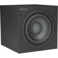
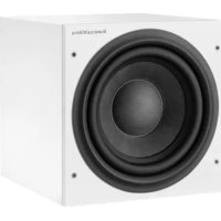
Thank you for purchasing this B&W Active Subwoofer.
Since its foundation in 1966, the continuing philosophy of B&W has been the quest for perfect sound reproduction. Inspired by the company's founder, the late John Bowers, this quest has entailed not only high investment in audio technology and innovation but also an abiding appreciation of music and the demands of film sound to ensure that the technology is put to maximum effect.
This subwoofer has been designed for Home Theatre installations and to augment the bass performance of 'full range' speakers in 2-channel audio use. Adding the subwoofer to your system not only extends the bass to lower frequencies, it improves the midrange clarity by reducing the low-frequency demands on your existing speakers.
Please read through this manual fully before using the subwoofer. All sound installations require some planning and experimentation if you are to get the best out of the products used and this manual will guide you in this process.
As the subwoofer is connected to the electricity power supply, it is important that you familiarise yourself with the safety instructions and heed all warnings.
Keep this manual in a safe place for future reference.
B&W loudspeakers are distributed to over 60 countries worldwide and we maintain an international network of carefully chosen and dedicated distributors. If you have a problem, which your dealer cannot resolve, our distributors will be more than willing to assist you.
The easiest way to unpack the subwoofer and avoid damage is as follows:
- Open the carton flaps right back and invert the carton and contents.
- Lift the carton away from the product.
We recommend that you retain the packaging for future use.
In addition to this manual, the carton should contain:
1 Subwoofer
1 International warranty document
1 Heat sink
2 Speaker level connectors
3 Line level sockets
4 EQ (equalisation) switch
5 LOW-PASS FILTER frequency control
6 PHASE switch
7 LOW-PASS FILTER defeat switch
8 MODE On/Auto switch
9 On/Standby indicator light
10 VOLUME control
11 Power cord
12 POWER On/Off switch
What the subwoofer does
Application: Home Theatre
The primary function of the subwoofer is to reproduce signals from the Low Frequency Effects (LFE) channel. In addition, the processor may be configured to divert the low bass portion of some or all of the other channels and add it to the LFE information by configuring those speakers to 'small' in the processor set-up procedure.
Application: 2-channel audio
The subwoofer is used to extend the bass response beyond that provided by the satellite speakers. In most cases, best results are obtained if the satellite speakers are run full range as normal directly from the power amplifier. The subwoofer low-pass filter is then set so that its output rises as that of the satellite speakers falls naturally. However, if the satellite speakers are very small, the system output level may be limited by overloading their bass drivers. If this is the case, better results may be obtained by using the high-pass filters in the subwoofer to limit the bass energy fed to the satellite speakers.
Positioning the subwoofer
Because the subwoofer produces only low-frequency sounds, positioning is less critical in some respects compared to full-range speakers. Directional information is much less precise and you have more choice where to place the speakers to good effect. This said, best results are obtained if the subwoofer is placed between the left and right speakers or in the vicinity of one of them. If you use two subwoofer, it is best to put one near the left and one near the right speaker.
Placing the subwoofer behind the listeners, even in surround sound installations, generally gives inferior imaging, but may be an acceptable compromise if domestic considerations dictate.
As with all speakers, the proximity of room boundaries affects the sound. Bass is generally increased as more surfaces come into close proximity with the speakers. Unlike full-range speakers, however, you can always restore the correct overall system balance by adjusting the volume level of the subwoofer. The more boost you get from the room, the less hard the speaker has to work; but there is a down side. Corner positions often excite more low-frequency room resonances, making the bass more uneven with frequency. There is no substitute for experiment as all rooms behave differently, so try the subwoofer in a variety of positions before making a final decision. A piece of music with a bass line ascending or descending the musical scale is useful for assessing the smoothness of the bass response. Listen for exaggerated or quiet notes. Having a separate subwoofer does enable you to optimise for room resonances independently from sitting the satellite speakers for best imaging.
Electrical connections
Disconnect all sound system equipment from the power supply until the signal connections have been made and checked. This avoids the risk of damage whilst connections are made or broken.
The subwoofer will input and output both line-level signals via the RCA Phono sockets and speaker level signals via the binding posts located on the back panel.
Use the following guide to select the correct wiring method for your installation:
Application: Home Theatre
Processor with separate power amplifiers feeding one or more subwoofoers - fig 3
Processor with integrated power amplifiers feeding one or more subwoofoers:
with line level subwoofer output - fig 4
- with speaker level subwoofer output - fig 5
Application: 2-channel audio
Separate pre- & power amplifiers:
Full range signal to satellite speakers and:
-One subwoofer -fig 6
Two subwoofoers - fig 7
- High-pass signal to satellite speakers and:
-One subwoofer -fig 8
- Two subwoofoers - fig 9
Integrated pre- & power amplifier:
Full range signal to satellite speakers and:
-One subwoofer -fig 10
- Two subwoofoers - fig 11
- High-pass signal to satellite speakers and:
- One subwoofer - fig 12
- Two subwooers - fig 13
Using more than one subwoofer
Using more than one unit in a single installation can improve performance in the following ways:
-
Maintain stereo separation to the lowest frequencies.
Cope with larger listening rooms.
-
Enable greater maximum sound output – often useful for effectively reproducing special effects in Home Theatre applications.
- Smooth out the effects of low-frequency room resonances.
If you are using two subwooers for 2-channel audio, stereo separation is improved if each channel has its own subwoofer, providing each one is placed close to the relevant satellite speaker. Only use the mono connection of figure 8 if you cannot place each subwoofer close to its satellite speaker.
Double-check the connections
ENSURE THAT THE VOLTAGE INDICATED ON THE AMPLIFIER PANEL MATCHES THAT OF THE POWER SUPPLY.
Before auditioning the sound quality of your new installation and fine-tuning it, double-check the connections. All too often, users complain that they cannot get a decent sound however they set the controls, only to discover something has been wrongly connected. Make sure that:
- The phasing is correct - there should be no positive to negative connections to the satellite speakers. If something is out of phase you may get a fuzzy sound with an imprecise and floating image, a lack of bass or a combination of the two.
- There are no left to right mix-ups – this can result, for example, in the orchestra being the wrong way round or, more dramatically, sounds on your Home Theatre going in the opposite direction to the action on the screen.
Switching on and off
We recommend that you switch the subwoofer on before any power amplifiers receiving signals from the subwoofer. Similarly, when switching off, switch the subwoofer off last.
THE MODE On/Auto switch (8) and indicator light (9) operate as follows:
On:
With the switch in this position, the amplifier remains permanently fully active, and the light glows green.
Auto:
On first switching on the subwoofer while set to Auto, the amplifier becomes fully active and the light (9) glows green. After a period of about 5 minutes without an input signal, the amplifier automatically reverts to standby mode, and the light glows red. When an input signal is detected, the amplifier automatically becomes fully active and the light glows green.
Setting the controls
There are 5 controls to consider:
The VOLUME control (10)
- The LOW-PASS FILTER frequency control (5)
The LOW-PASS FILTER switch (7)
The PHASE switch (6)
The EQ (equalisation) switch (4)
The optimum settings depend on the other equipment used with the subwoofer. If using more than one subwoofer, ensure the controls on each one are set the same.
Home theatre
The subwoofer is not a THX^ licensed component, but may be used with a THX^ controller if desired.
- Set the VOLUME control initially to the 9 o'clock position.
- Set the LOW-PASS FILTER switch to OUT.
- Set the EQ switch initially to position A.
- Set the PHASE switch initially to 0^ .
- The setting of the LOW-PASS FILTER frequency control is irrelevant.
See also the section "Fine tuning".
If you have a THX^ controller, ensure that the subwoofer function is enabled. When so configured it incorporates all the filtering and level setting required for the subwoofer in all modes. For level calibration, the internal test noise and channel level controls in the THX^ controller should be used. In all cases the levels should be set to obtain 75dB SPL (C-weighted) at the listening position from the controller's internal noise test signal.
With other processors, configure the front and surround speakers to "large" or "small" as appropriate before setting the levels. Use the internal noise test signal and volume controls of the processor to set the levels of all the speakers. Only change the VOLUME control on the subwoofer if there is not enough range in the processor to achieve the correct levels.
Inexpensive sound level meters are readily available from electronics stores and should be used to calibrate the levels. Refer to your processor manual for further details on how to set the levels.
2-channel audio
- Set the VOLUME control initially to the 9 o'clock position.
- Set the LOW-PASS FILTER switch to IN.
- Set the EQ switch initially to position A.
- Set the PHASE switch initially to 180^ .
If you are running the satellite speakers full range (figs 6, 7, 10, 11).
- Set the LOW-PASS FILTER frequency to the -6dB cut-off frequency of your satellite speakers.
Both -3dB and -6dB figures are to be found in the specification of each B&W speaker model. However, if the manufacturer of the satellite speakers does not quote a -6dB frequency, but only a -3dB frequency, the optimum setting for the LOW-PASS FILTER frequency control will be between 0.6 and 0.9 times the -3dB frequency, depending on the roll-off alignment. The more gradual the roll-off rate of the satellite speakers, the lower the frequency should be set.
If you are running the satellite speakers high-passed (figs 8, 9, 12, 13).
- Set the LOW-PASS FILTER frequency initially to 80Hz .
See also the section "Fine tuning".
Fine-tuning
Home theatre
With home theatre the subwoofer (LFE) signal is a separate channel rather than an extension of the signal to the satellite speakers. The LOW-PASS FILTER is switched out, because the processor provides all the filtering for any speakers set to "small". However, the position of the phase switch must still be assessed. Normally the phase will be set to 0^ , but if the subwoofer is positioned at a distance significantly different from the other speakers, or the power amplifier driving the other speakers happens to invert the signal, the 180^ position may be preferable. Listen with the switch in both positions and choose the one that gives the fullest sound. If there is little difference, leave the switch at 0^ .
Surround sound processors normally have a calibrated noise signal that can be used to set the relative levels of all the speakers, making the task somewhat more straightforward than for 2-channel audio. However, do not be afraid to alter the settings to your personal preference. It is all too easy to get carried away with the capabilities of the subwoofer, especially with some special low-frequency effects. Often a more realistic portrayal, and one more satisfying in the long term, is to be had by setting the subwoofer level lower than the standard calibration level.
2-channel audio
The optimum settings of the PHASE switch and the LOW-PASS FILTER frequency control are inter-related and also dependent on the low-frequency cut-off characteristic of the satellite speaker. However, the settings recommended above for the LOW-PASS FILTER frequency and PHASE have been chosen to add well to most bass alignments, whether closed-box or vented-box (reflex), with -dB frequencies within the adjustment range of the subwoofer.
If feeding the satellite speakers via the high-pass filter of the subwoofer, the frequency will need to be set lower than the initial value of 80Hz if the -3dB frequency of the satellite speakers is lower than 80Hz and higher if above.
Set the system up in the preferred position and play some programme with a steady bass content.
Using the initial settings guide, first check the setting of the PHASE switch. Choose the position that gives the fullest sound. Normally the recommended position will be optimum, but may not be in certain circumstances, such as if you are using line level connections and the power amplifiers feeding the satellite speakers invert the signal, or if the subwoofoers are not placed close to the satellite speakers.
Next, set the loudness of the subwoofer relative to the satellite systems to your liking. Use a wide variety of programme material to get an average setting. One that sounds impressive on one piece may sound overpowering on another. Listen at realistic levels as the perception of balance varies with sound level.
Finally, adjust the LOW-PASS FILTER frequency to give the smoothest transition between the subwoofer and satellite speakers. This is probably the most difficult to optimise.
All applications
The EQ switch alters the bass roll-off alignment. The bass you hear is a combination of the subwoofer plus the effects of the room and you should choose the position that best complements your room and the position of the subwoofer. Position A gives a drier alignment, more suited to placing the subwoofer in a corner or compensating a boomy room. Position B is more suited to a dry room acoustic and use away from a corner.
If you get problems with uneven bass - if certain bass notes are exaggerated more than others - then you probably have a room interface problem and it is worth experimenting with the placement of the subwoofer. What may seem like small changes in position - 15cm (6in) or so - can have a profound effect on the sound. Try raising the subwoofer clear of the floor as well as lateral movement. The use of multiple subwoofer can smooth the effects of room resonances, as each subwoofer will tend to excite resonances at different frequencies. If you alter the relative distances from the subwoofer(s) and satellite speakers to the listeners appreciably, reassess the phase switch setting. You should also check the level setting of the subwoofer (using either the processor output levels or the volume control on the subwoofer amplifier as appropriate), but only after setting the phase correctly.
When using more than one subwoofer, ensure that each one has its LOW-PASS FILTER frequency and PHASE set the same way.
Taking care of the subwoofer
The cabinet of the subwoofer may be cleaned by dusting with a dry cloth. If you wish to use an aerosol cleaning spray, do not spray directly on the cabinet; spray onto the cloth. Remove the grille first so that the cloth does not become stained, but be careful not to disturb the drive unit. The grille itself may be cleaned using a soft brush.
Do not use the subwoofer as a table. When in use, objects left on top of the subwoofer are liable to rattle. In particular, avoid the risk of liquids being spilled (eg from drinks or vases of flowers).
If the system is taken out of use for a long period, disconnect the subwoofer from the power supply.
François
Garantie limitee
Cher Client,
Bienvenue à B&W.
Se tem as colunas satelite com saida de altas Frequencias (figs 8, 9, 12, 13)
Defina a féquence do FILTRO PASSABAIXO inicialmente para 80Hz.
PykoBoDCTBO IO 3KcnplyaTaunI
BAKHbIE MHCTPyKcN\PO BE3OpACHOCTN

BHMAHNA SINGHOSO NONGKOWI HONGKONG HONGKONG HEOTKIPBATB

BhimaHne:
ДднСИКЕНЯОТАССТУРОТЕ
ЗЛЕКТРИСЕСКIM TOKOM HE CHIMAJTE
3AZHIOO NAPIJIb. BHYTRN HET ZEМЕNTOB,
HE06XODMHBIX NOJIb3OBOATEIIO.
ПгEDOTABTe TEXNHUYCECKOE
OBcLYJxNBAHHe KBAJIINФИЦИРОВAHMY
nePCHOANY.
OBJcHHe rpaФuYeCKNX CUMBOJOB:

N360paBHOCTOPOHHE
TpeYIbnHke
npEynPexJaet O HanuHn
BHYrpnKOpNcya N3JenIn
Hen3OJImPoBaHNo
HaNPaRKeHnA,BeMNHn
KOTopoMOKjET CO3DaBaTb
OnaCHOCb TPOPAKeHnA
YeNoBeKa 3NeKTPnueCKM
TOKOM.

I3604aXeHne BOCKJIuaTeNbHO 3NaKa BPAHbOcTOPOHNEM TpeYIbNHke IpeDynpEkaTeAOT MO, YTOB COnpOBdntEJbHON DOKYMHeTAuIN HA3dJIeN MeIEOTCBAxHbIe HnCTpyKUcNI PO KxCNyIaTauN INTEXHueCKOMY O6CbNyXbAHIO.
PNEpyPEXKDEHNA:
1 PnOHTInTe NHCtpyKun -Ipeed nauJOM 3KcNpyatauun 13dEnJIH ne6xOIMO npocTeB cE hNCTpyKun no TeXNHKe 6eONaCHOCTn 3KcNpyatauun.
2 CoxpaHnIe HnCTpyKuIN - HnCTpyKuIN NO TeXnHke 63oNaChOCTN I KcPnPyatauIN hoeXbDmIO coXpaHnTbI nOpCneDyUOHX cnpAOK.
3 O6paaIte BHMMaHHe Ha npedocTepeKHeHa - Heo6xOdimo yuHTbBaTb BCE pndocTepeKHeHa, yka3AHHBe Hn 3eNIN N B nHCTpyuXnX no eRTOcknYatau.
4 Cnedyte NHTcpykunm - Heo6xOIMO cneObaTb CeM nHTcypKUnm O NKcNlpyatauN.
5 IVctOuHnK nITaHnR -3To m3dEne cNdyET nODcoeAHINb K IcHTOHmky nITAHnT OIbKO TOrO TiNa, KOTOpBiy ykazaaHa 3aDHe naHEIn. EcnB BbI he 3HaTe napAmTePOB 3NeKtPoCteBn BaWaeDMo, o6patntecb K Baawemy dIJIepy mN bMeCTHyO 3NeKtPnuCeCKyIO kOMAnHIO.
6 3a3emnneH n c06IouHe H nonrphOCTn -3Tn o3dJeHn He Tpe6ybet 3a3eMnHn. Y6edntecb, yTO BnIka nONHOCTbIO BCTaBNeHa B CTENHYO PO3ETKY mNIN BPO3ETKY yDInHNTeR, IaI npeoTbPaueHHn PNOAeHHn 3JNEKTpUeCKN TKOMK. Ecnn Bbl NOnb3yeTeCb yDInHNTeMeN mNl shyPOM nITAHnE, HE BXoJHMn B KomPNkET hNDEJIin, pOncNdte, yTO6bI OH bJI O6OpdyOBan NtBIMn BnIKAMn COOTBTCTBOBAN pINHtBMn BAeien cTpahe Hopmam 3NeKTPO630anACNoTHc.
73aunita shnypob nntanraH NHybprnTANHn DONKhbl npoklaabBaTcB TaKIM oB6a30m,TOb6bHa HNHe Hactynannn He 3aDeBaan KacmmNIn6o npedmetamn;Obpaasute OOCOb BHNAMAHne Ha MeCTa B6bnin
BWNOK, UTENCebHbX p3aBEMOB bBxOda hUpy a3 KNPcya 3dENm.
8 Nperpnyka - He neperpkyaite po3eTkn 3neKTPocetn YuDInHNTeni, TAK KAK 3TO MoKET npINBcTeN K BO3rOpaHIO INI NOPaxEHHIO 3NeKTPuYeCKM TOKOM.
9 BeHTINIaIIaI - IaHHeNb ycInnTeJIaB 3aHneJ aactu HnIeNBI RbIaETcY aTaBtIO CNTeMIbOxLnXaJIeDHNi He DoIKNHa 3aRopaxBaTbcI INn NOKpbIbTaCB. He PaM3eauIte I3dIeHI Na KpOAtn CoFe, KOpe INn NIOo6HO MIRKO NOBepXHOCTN. Y6eIITecb, YTOpeBaPaIaNATOpa OPmEHTPOBaHb BErTKaJIbHO DnIg OBeCneUHn DOnKHO rOxLnXaJIeHN. He CNeyET BCTPamBaTb H3dJIeN B CTOnK, ONIKN, IaIuNK, ECNI TAm He OBeCneUBAETc DOCTAOHAR BENTIaIIaN 3TO He pa3peSeHO B INhCTPyKuIN XPOIN3BOITeJIaN.
10 NCTOChHKn TEnla -N3dEJIne cNeIyTeP a3MaUaTb BDAJIIN OT NCTOCHNKOB TEnla, TAKKx KAc paDnATOpBly, TENIOBLe 3aBeCsI, neu nnApyrnE pN6OpB (BKNIouy ycNITeIN), KOtOpBle BbDEJIHOJ TEnNO.
11 HacteHbMoHTaK uNkKePJIeHne KNOTOnky - N3dEne CnDyET MOHTIPOBaTb Ha CTeNe HnHa NOTOnke TOnbKO B COOTBCTBmC peKoMeHdaaHmNtROBtTeJ.
12 Boda n Blara - He nCnOB3yIte 3To n3dJIne B6JIMn BObl - HaprMep, pRDM C BAHOH, PAKBOHIO, KXYOHHO MOKOH, CTIPaNbHOH MaIHNO; B NOBaIaNAX C NOBbIeHNHO BIAxHOCTbIO IN PRAOM C nnabATEbHBM BACCEHOM n.T.N.
13 PIONADAHNE BNYtpb npedmetob IN KIHKOCTeH - KIOHOJa DEBCTANIE KAKeIeNIO ppeMeTb IB 3TO N3dJIeNe Uepe3 OTBepCTnA, TAK KAc OH MOryT KOCHyTBCr TOEK NOI ONAOChbIM HApRAKeHNEM ININ Bbl3BaTbK KOpOTKoe 3aMbKaHne, YTO MOKETnpBVBeCTn KOB3OpaHNI IOI NOPaJEHNIO 3NeKTPnuCeKM TOKOM. HIOKOHa NEpONBaJIte KaKyo-NIO bIKoKocTb HA N3dJIeNe. He CTABtBE Ha N3dJIeNE EMcKcTn, HAnONHeHHbE KIKOCCTbIO.
14 OuCTKa -IpeD OIcTCKo BbHbTe Bnky Ihpy nIaTHnA 3TOrN u3dJIra nO3pOeTKI 3JIeKTOpcOTi. PekOMHeauIN NO OcHTKe npIBVeHb I pa3JeE "YxoJ 3a c6BcypePom
15 PnncnoocbneHn - He noIb3yItecb npncnoocbneHNHM,He peKOMeHNoBaHbIMn I3rOToBnTeJEM, TaK KAK 3TO MOKeT pNBeCTn K ONaCHbIM CNTyaUAM.
16 PrinahdNEXHOCTn - He pa3meuaIe I3dEJIne Ha eHTOCHIVBOn TEaKHe, CTOKE, KPOHUTeHne HNI CTONE. I3dEJIne MOKET ynaCTb, HNaHEc cepb3HyIO TaBPMypeB6eHKy INI B3PcOJMYn IcMoNpyNTb NOpeKJENHIA. IcONp3bYITE ToNkBO peKOMEnHOBaHnble N3rTOBHTeMeIe INI BXDQAMIE B KOMINJEKT N3dEJIne
CTOKNI T.II.JIIO60MOTMAK
N3DEHNI CYEET NPOBOYITb TOLKBO
B COOTBETCBMN C HNCTPKYKINAMN
N3TOTOBHTIELA, A MOHTAKHJIbe
PnICNOCO6JIeHNA DOLKJIb 6blTb
PEKOMHNDBAHNA I3TOFTBNTENEM.
17 PēneMeēηHé - TeNéKxy c yctaHOBJIeHNbM ɪsIdIeM CneIyET peNéMaHTa bOcTOPOxHo. PeZekn oCTaHOBKn, npIIOJKeHne ɪsIJIuShnX yCNIi N hePOBbI N O N MOrT pyINBeCTN K ONpOKIbIbAHNO TēneKKn. He Taùnte ɪsIdIeN BOLOKOM, ta KaK KOJIuečKne O nOpbl MoryT OTlOMnITbCt O K pOpyca N Bly3BaTb NOBpEzDHH.
18 NpepebBv BnCnOlb3oBaHn -Ecnn n3dIeMne npDnIonaeraTc DOnro He nCnOlb3oBaTb, BbHbTe BnIKy Uhpya nHTAHA HnP3OETK 3JIeKTPOCTeN.
19 06cIyKbAHnhe - He nbIaTaeBc 06cIyKbAHbTe 3To 13eIeNAMCOTOrTeBHO, TAK KAK pIe OTKpbAHm INI CNrTHM KpbIeK Bbl MoKeTe NOIacbTPOd ONaChoe DnJ XKnHn HaprrKeHne NIOBpeBaPraTe Ce6I dpytMOnaCHoCTM. PnpOCTabBe TExNHueckoe 06cIyKbAHnHe KBALINDIIuropOBaHHOMy nepcoHany.
20 Nobpej.DEHnI, Tpe6yOuShne TeXnueCkTOO oCbNjXbAHnI -BbHtBe NbUky Ushya PmTAnHn3 TOrTO n3dEHN I3 pO3ETKn ALeKTPoCSTn I 6paTInTeBc K KbAunHmUPOBaHOMy MaCTepY CneLHyOnuCityaN
A NpOeXJDeHbI shyP nITAHn IIN BUNK;
6 BnytbI mIeIaI nnIani pIeMTeBtI IINI KJIOKcTb;
M3EINeIIOIaBeproNcB0B3EJCTBNIO DOxJrN IIN BOBdI;
rI3dienhe He o6cneuBaet HOpMaJIbHyIO paOToI npri BbIOIOHNHm INHTpyKmIIO 9KcNpIyatauIM. POnb3SyITeCb TolbKO yKa3aHHbIMB INCHTpyKmIHX IO KcNpIyTaUIM OprAHAM YnpAraBHeNIA, TAK KAe HnpeBaINbHOe NPOBeHene npoQHx perNJpOBOK MOkET pNpBECTK NOBPeJDeHNM, YcTpaHenne KOTopbIX NOTpe6yEt CNOXHO rPEMOHTCA pNpBENeHEnEM BbICOKKBaIIΦmIupoBAHONHO nepcoHaJAA.
ДИЗдение Oнгани Ино Имeelдурney NOBPEKDEHnI.
e Pino30ouHn 3aMeTHbIe N3MeHEN HBa6Ote N3dEnJIr-3TO yKa3bYBaET Ha HeO6XoIMOCtB npOBeDEHNrTexHcECKOrO 06CNYxBAHNAr.
21 3aMeHa Detanien -Korda tpe6yetc
3aMeHa DetaneiyeBdTeCB TOM,
YTO MaTePycTahABINBaET Detanl,
PEKOMHDoBAHNbHe NtOToBAtENe,
nIM MHeoune XapakTepCTNkI,
aHAnOrHbNe OpeRInHaNbHM
DetanlM.HeaBtOpINoBOAHNA 3aMeHa
3aTeanE MoXeT pInBeCTN K
BO3rOpaHnIO, nopAKeHHIO
3NEKTPINHECKMUM TOKOM INDyTNM ONAOBCHIM CNTAYUAMR.
22 Cetebbpe npdoxpanHTenn HnOaTcTaB BWTpy cynlTey. Nx 3aMeHa DoJXHka IpnO3BDnTbCS nepcohanOM, ABTOP3OBaHNbIM B&W. Tmbl npdoxpanHTeney kka3aHb b CneuDfKauInx.
23 PnOBeRka 6e3oNaChOCTN - Nocne 3aBePeHNe HIOBO O6cLyJbAHBaNH Nm pEmOHa 3TOrO INdEnJe nonpocInTe MaCTepa npOBeCTn nPpOBeky 6e3oNaChOCTN, YTObIy yEeNTbcB TOM, YTO INdEnJIe NOrTOBtHO E K 3KcINyatauN.
24MaHTHThIbe NOJI -3TO n3dJIeNo 03daET CTaTHueCKOE MaHTHThOE nOpePacRHeN. He pAsMeuaIte npEdMeTb,Ha KOTOpBe MOKeT JOBnARbMHTHcHoe NOn (HANPMep, TENEBnOBoI M MOHTOpbl C 3NeKTPoHNO-lyueBbIMN Tpy6kAmi,ayIO IN BIEO KACCtE, MaHTHThIE KapTb) 6bnke 0,0 MT n3dJIe.Ha ManOp PocToCTHO m3dJIeN CNOC6HO Bb3BaTb NcKaXeHne H3obpaXeHn,pepeDaBaEMOrO 3NeKTPoHO-NyueYeoT py6KOh.
BveeHne
Blaorapm 3a npno6peTHe nA kTNBHOcabyfepe (H3K0CACTOHTOH akyCTNHECKOINCTEMbI) pON3BOCDtBA KOMnann B&W.
Co BpeMeHN OCHOBAnH B 1966 roy, KOMnAHn Bowers &Wilns cserda CTaBNIA CBOW CEIbHO 63zynpeHoe BOCpON3BedeHne 3Byka. BoOdyueBHeMaHAR B 30M CTpeMeHN HCBOM OCHOBATEHm, HbHIe NIOKbHM IJxOHOM BayrPCOM, KOMnAHN BKlaDbuBA BoNbUme CpTeDAH TeTOLKBo P3aPbOtTKO HOBeIMHX ayDINO TExHOLOH, HO b NOCTOHHOE INYcHHe NOC6EHOTNE COBPEMEHN My3bIKn IN KHO, YTO6bI hCNOI30BaTb 3TN TEXHOJIAN MAKCIMANsHb 3qFKeTINBO.
3TOT cabyfepe 6bI pa3pa60an dnn
ncnObn3oBAnH B KaeeCTBe
akcYnueckOnCnTeMe (AC) DAmuHero
TeaPra, a TaKxne JnTO, TTo6bl
NoBlcITb yOpBeH baca B
DByXkAnHLbN NoNHOaNA3OHNO
ayDiocnTeMe. Do6BaKa cabSypepa K
Baue aydiocnTeMe N3BOJrET He
Tolbko pacSiPrNT b cacobu dImana3OH do
HaHObOE Hn3KKn YAcTOn, Ho n CSeNa
UHue 3ByaHHe CpeDHe rDaNA3OHa,
ChnJaHn3KoAchToTHyO harpy3Ky Ha
Bauu KOLOHNK.
ItoKAnJyBtA, BnHMATEbHb NpOHTte daHnoe pyKOBoDCTBO nepei cnNcNo30BaHHe CaOBYpeBa. HacTpoKa IIO6a oyIMocTeTBe Tpe8yET nnHApOBaHHN 3KcNEpMnE7a Jn DOctmXeHNHaHnUyWTo pe3ynbTaTa, n daHnoe pyKOBoDCTBO nMOxet Bam B 3OTM.
До Клioченяса6bbyфетаК
ДэктrocETи Heo6xOДМО 03нakOMTbCЯ
CO BCEMN INCHTpKUIMN NO
БezoanchoCTNi npeynpEeJHnIMN.
POMeCTNE 3TO pyKOBOCTBO B HAdEJXHOE MecTOne 6bDyUHn CPNABOK.
Akyctuueckne CnCTeMbI KOMmaHIN B&W
noCTabAAHOTcB 6 BoJee CHe 60 CTpaH no
BCMeY MMpy, N haAsa KOMmaHIN
noDaePcxBaET MExJyHapOHyIO CeTb
TuATeJIbHO OTObPAHbIX N
BbICOKOBaHmFInOpBOAHbIX
NtCtPb6bTOpOB. EcN y Bac BO3HNKHT
npOBeMa, c KOToPoH He MOKeT
CnpABITcBdIJIep, NaHNI
NtCtPb6bIoTpBcOxOtHO npDyT BaH na
NoOMoUb.
PacnaKobka (pnc.1)
Hnke onncan npocteu nn cnooc6 paacnakobkn cbayepa 6e3 nopebckdenn:
- OTORHHTe BepXHnE KnaIaHbI Kopo6Kn
- n pepeBepHnTe e BMeCTe C
- CODePXDnMbIM.
- CHIMITE Kopo6ky c annapata.
Mby pekomeHnyem coxpaHntb ynaKOBky dIaNcNoJIb3OBAHnB 6dyuEe.
3NeKtpnueckne coeHHeHn
Bo 136exaHne nobpeXdHnO tcoeHNHTe nHTAHE BCero ayDINO oobpyoBaHnHa bVpembO cOyEcTbEnHnN npOpreKn pOncOeHNHeN.
K Ca6b7epey NIOBDAIcT N OTBDAIcT CnHnAbl NIIHNEHORO YOUPBaY CheE3 rhe3da RCA, A taKke cInHaJIb BILCOKOrO YOpBNa YpeE3 KIeMMbl, paCNOLOKeHHbHe Ha 3aJdHn PAHEn.
Bb6ipraanCno6oCoBDnHNEA Baaew aayDnOnciTeMbI,BOCNOp3yTneCB cnDEynOnMMPeKOMEnDaunMm:
Птумени: Домашни TeaTp
Piooeecop 6e3 BCTPOEHbIX yCINNTEN MOoHcTn, nHTaHne OJNDHO nn 00ee cabeYcepeB- pnc.3
Pioeecopp CO BCTPOEHbIMN yCNITeMaM MOUHOCTN, NITaHNe OHDORn 00neCabeBypeoB:
c BbXoDM nIa cBbyΦepa IInHeHOrO yOpBNa -PNC.4
- C bviXODOM nIaCB6yΦepa BbICOKOTo yOpBNA -PMC.5
Пrimеренemes:2-kaanbna hyaundocntema
COTeBnHbMnpEpyCNiHTENEM yCNiHTENEMOCHNTO:
-Плноданаэзнburnи сгнан на сателтупaxи:
- OdHn ca6ByΦeP - pnc. 6
-Два ca6Byepa-pnc.7
-ФильтобааньиВСИгнан ha cateINETNATXи:
- Odnh ca6Bypep - pnc.8
-Два ca6Bypepa-pnc.9
C INTERPPOBABHBMN pRyEDcYNLTENEM yUCYNLTENEM MOUHCTOM
-Плноданаэзн宪и сгнан на сателл taxи:
- Odnca6Bypep - pnc. 10
-Два ca6Byфepa-pnc.11
-ФильтобаньиВСИгнан ha cateINITAXи:
- Odnh ca6ByΦep - pnc. 12
-Два ca6byфера - рис.13
IcnoB3OBAHne HeckoJIbKnx ca6ByΦepeOB
Icnobn3oBaanhe 60nee, cem Ondoro ca6byePepa B OOnH ayuNOCINCTeMe MOKET ynyuHTB BOCPNo3BeHnE 3Byka cnDyUOUMN CNOCOBAM:
Пдержka радзенич STЕРКANHOB DOcambIX NHKHXVACTOT.
CnOcObHOCTb CNTeMbI Ka pOBe T B oBbIXN NOMEHHINX.
- OctnHexHe6 0bnIeMakcImaIbHO MOuHcTo 3ByKa, 0TuYUHaeT BOCPON3BcEHeH3 BYKOBXb 3ΦΦeKTOB B DOMaUHEM KINHOtePe.
- YMHeBSheHne BInaHHn Hn3KouchToTHOrO pe3OHaHcA nOmoUeHHN.
B2-kaHbNHO ayDIOOCNTME
pa3dJIeHHe CTpeO KaHANOB
yUyNcTc TpN yCObNn, YTOKaKDb
KaHAn OChaIeH CBoHM Ca6ByΦepOM,
pacNoJoxEHb JM prAD Co CBoE
KoJNOHc-KatETNtOM. EcnI Bb He
MOKeTbe 06eCneHTb TakoE
pacNoJoxEHce, CNeJyET NcPb3OBA Tb
MOHO CoOeMHHe, NOKaAHHoe Ha nC.8.
Поверка правлььhoeст норкlioан
VBJEITIECb, YTO HANPJAKEHNE 3JEKTCPOCTEC COOTBETCTBYET IAPAMETPAM NITAIIOLETO HANPJAKEHNE,YKA3AHHBIM HA PAHEJIYUCNIITEJI
PepnDpoBepKKaeeCTBa3BvAnHn HOBoAaHNOcICTeMbI N eE ToHNoH NaTcPOKIOB,DAbXdJIbPoBepTe npabNtBHOCTb BCeX CoEduHEnH. PnB3OBeTne YactO XaJyTOc,TTO He MOrY TdoobTcXPOwEo 3BvAnHn CSteMbI BHe 3aBnCmOcTOn eE perynnpOBKn. 3To, KaK npaBnO, Bb3BaHO nepaBnBbMn oKnKIOueHem. Y6bdntcebB Tom,TO:
- PnabInbNo Bb6pAbaФa3a - nOIOXINTeBHe KEMMa He DOJNHi b6bIb NOdkIOUeHbK O TPOUATeBbHM KEMMM KOHOOK.HenpaBnBbH bB6OpFa3b npBOMDNT K pa3MbTOCTN 3BYKa C HyeCTOnuHBm 3ByKObIM O6p3oM INI K HEXBaTKe 6acOB, INI K TOMY IN K DpyROMy BMcTe.
- Pnabii N neBb KaHaJIb He nepenyeTaNb.3To MoKet npBeCTN K TOMY, 7TO, cKaXeM, 3ByaHne HNCTPymENTOB BOpKcTepe NOKaXeTc8epKaIbHO OTPaKeHHbIM nJHNe, 7TO eEe 6Oene HEnpRTHO, 3ByuKHe 6yDyT CoNbAdTa C pOnCXoJaHm Ha 3kPaHe TENEVB3Opa.
BkIIOUeHne BbIKIOUeHne NITAHNA
MbI peKoMeHdYeM BkIIOUaTb Ca6bByfep
O bKlIOUeHHN YcINHTeJIe MOnHOctn,
nOnyuaIOuNX CmHN T o Ca6bByfepa, a
BbIKIOUaTb eRo, Hao6OpOT, NoocEHNm.
PteKeKIOuOATEnb MODE On/Auto (8) nCBTeOBou HnDkaTOp (9) pa6oTaOT cnEduNtOMB opzAm03:
On:
PnnepeKniOuOteNe B 3OM NOIOXeHIN, yCUNIeTb NOCTOHHO OCTaTcR BKIOUoyEHbIM IN CBETOBIO INDkAToP CBEITRC3eNEHbIM CBToE.
Auto:
Пппөрьм ВКлчουни сабыфера в
авTO-рхиме, усИNTеь ПОИСТь
ВКлчоаетсЯ CBETOBУ ИДИКATOP (9)
CBETITCR 3EнБун CBETOM. ПИМЕХО
Черз 5 МИНТ, ECINHA BXOD He
NOCYTNIN CIRHAN, YCINITeB
АВOTMATTUCHEN KEPEXOДN B PEXIMK
ROTOBHOCN IN CBET INDAKTOPA MEHHETCR
Ha KpaChbI. PnO6hApyKeHNB BXoHOrO
CINHala YcINNTeB ABOTAMUWeCKN
pePexOaHT B paOchY peXmN I INdIKATOP CTaHOBINCT 3eNoHbM
Hactpoika ca6Bypepa
Ca6Bypep Cha6xhen 5-o oprahamn yunpaanee
- Peryntopom rpoMkoCTn (VOLUME) (10)
PergnTTOPM rpaHnnHnOaCTbH NcHnTpa (LOW-PASS FILTER) (5)
- Běkličnočašeněm HU φúnl'tpa (LOW-PASS FILTER IN/OUT) (7)
- PerekJIIOuTeJIeM Za3bl (PHASE) (6)
- Пеклочателем счоттонов короксян (EQ) (4)
OnTImaJIbHoe nIoNoXeHHepe rpyIaTOpob 3aBcIcNTo TOrO, KaKoe o6OpYobAhnE nICIOJIb3yETC cOBMeCTHO CcbByFepOM. Pn IcNOJb3ObaHNbO BoJe OdHOro cBaCyFepa, Y6EdNITcB, YTO peryIaTOpbl o6Ox cBaByFepOB hAxOJaTcB OdINHaKOBOM nIoXeHENm.
B domaunhem teaTpe
CaBbyepe He RbIeTcnaHEnHIOPOBAHHbIM KOMNOHOENTOM THX,HO,pnJxenaaHNMOKET6bITbNCNOb3BOaH C KOHTPONJIePOM THX
YCTAOHOBITE peryraTOp VOLUME B NOXENHEM "9'acob"
- YCTAHOBITE BbIKIOHATEnb LOWPASS FILTER B noIooJeHne OUT(BbIKIOeH).
PepoBHOaHbJIyO, bHTaOHOBITE PEPKIOUaHTeBJEQ B NOJONOEHEA
- PēpBoHauJIbHo, yctaHOBnTe nepeKJIoUcTaTeN PBHASE B nOJoxEHe O°.
- Поножение ретунлого LOW-PASS FILTER He IMeET 3нauчEquin.
См. takxe pa3dēn "Tohna Hactpoika".
EcnblnNoIb3yeTecb KOHTpOJInePOMTHX*y6eDntcB,TOAKTINBPOBAH erOpyHKNJIaCsbEyPeBa. B 30m clyaeKoHTpONIEp cam BblonIHAEETBCOfNtbpauIO CnHARNA IYCTAHOBKYypOBHJd nCaBsypeBa BOcePEKHMAX.ДЯ KANILBPOBKU yPBOHBr pOMKOCt nCneDyET mCNOI3OBAtTeTcBOBJ TReHEPATOP UyMA u peryNJATOpBIyOBHARKANAOB KOHTPOnJIpeBA THX*.BoBCEX cIyuaX Ha MeCe TPOCNUBAnHHaONKe HbItb DocTrHHT yPoBEHb3ByKOBOI dABJIENH5 75 bB (3BBeWHeHHNIO KPNBCO)Ha TcTeBOM CnHane.
PnpncnboaBannpynHex
npoccecoBOP,oxapakTepeu3yIe
pOoHTbHBe AC nTbIOBle AC KaK "60blwne"nnlMaIbe"pepeD
kAn6pOBKOyUPOBHNrPGOMKCTN.ДЯ
Kan16pOBKNyUPOBHrPGOMKCTN
InCNOb3yTE TeCTOBTHreHEpatOp SuMy
npeyraTObpYPOBHNKaHANOB
npoccecop.NmEHaNtENoJOnKHeHne
peyronrA TOVOLUME Ca6bypepaTbko
B Tom clyue,ecnnpocceCOP He
obadaet DoctatoChbIM dmAna3OHOMd
DOCTIXeHnI pabInbHO rPOBHNrPGOMKCTN.
IkaN6pOBKn yOoBnXopoWIOHb03BtEhDOpORne IM3MePHTeIN 3ByKOBOr DaBNEHnK, KOptObie npOdaOtCB mArasaHnxAteJcTPOHNHO nnapATpyb. IIOpaObo O kanIn6pOBKe yOoBn rPoMOKCTn CM. INCTpyKUIO NO 3KnCLyataaunnpOecoppa.
B 2-kaHajbHnoy aynocncteme
- YCTAOHOBITE peryiratop VOLUME B NOXENHEM "9'4C0B"
- YctaHOBITE BblkInouateIb LOWPASS FILTER B noJoxeHne IN (BknIOueH).
- IpeBOHauJIbNO, yCTaHONBEIeA nepeKNUOHTeB EQ B noJONOJEHne A
-пелованьно, установпениковOTеPHASEB nonoxhenne 180°.
EcnHnHa cATEeINITbI NOaETcN oNHOAna3oHNbI cRHaN (Pc.6,7, 10,11).
- YctahonBnte nepeKlnuOaTeNb LOWPASS FILTER ha Tu cactoty, Te xapaKtepncTnka caTeIInlntOB cnXnaTeCn ha -6 dB.
B TeKmHcckXn XapaKTpeNCTHX BCex AC B&W yka3aHbI rpaHnHbI cHaTObI no yOboHNO KAK-3 D5, TAK n-6 D5. EcnI npOnBaDHTeB AC yka3aIBaET ToIbKO cAtoT NO yOboHNO-3 D5, TO ONtHMnHba YCTAOHbKa peryIaTOpA LOW-PASS FILTER 6dTeM MeJy0.6 n0.9ymHOKHTb Na cAtoT NO yOboHNO-3 D5, B 3aBcIMCOnTn OKyTmHbN cnaJa. Yem 6oone NONORM ABnEITc cNaI, TEM 6oone Hn3Ka YAcToTA MoKET 6bYbYctAOBHeA.
Ecnna hataeIantbI npdaetcnaHbTPOBAHNbBCHcHnA (Pnc.8,9, 12,13).
- Yctanobinte nepeknohtenb LOWPASS FILTER nepbohaayabho ha80
Cm. TaKxe pa3deJ "ToUHa nAcTpoKa"
Toyna hactpoika
B domaunem Teatpe
Ioctyaiouhi na caboyfepe cnHnai HnKooaTcOTbXb3f0eKtOB (LFE) npedctabnaet c6oB OTdebnhKaan, a He npodonjkeHne CnHana, noDaabaemorHa n daytnye KOJNOHN. Hc fNbtp BbKnIOyeh, ta KAK npoeecopp oObeCNYBaTe BCIO fNbIbTaCmIO dlan IIObXb OKOHOK, OaxapkTeep3MObaHHbIX KaK "MaJIbe. OAnhao, noJONKeHIO nepeKNoUChTePA3by DOnJHXo 6bIb ydenho BNImaHne. OblyHNO f3a3 yCTaHApNBAeTcHnA 0^ HO eCIN cABsyFep paccONOxHnE raop3do 60blSeM paCCToHN ONcTyuSae, YcEM dpyrHe KOJNOHN, INI yCUnTIteB MOIOHCTN, nIITAOuoiDpyrKe NOJONKH, INIEBpETyET CnHnA, to NpOJOENHE 180 MOKET OKa3ATsCR npdnoOTtTeBHe. PpnO3BeNTe PnOcnuSHBaHme C nepeKNoUChTeB MBOxH NPOJKeHNAX i BblbepHTe To, KOtOpoe oOcneueNBAeT hAnBoee NauchHeHHe 3ByaHne. EcnI pa3Hnua He6oJIbSha, OCTabTe nepeKNoUChTe B NpOJOENHI O.
O6bHNO npoceccopby IMeIOT TcTeobbl
rheepatop MuyOBORO CnHana,
ncPONb3yEMBn Dn yCTaHOBNK
OTHOcNTeBLhX yPOBHe rPMKocT BxCEKOLOHOK, YTO6NEeHT aHcTPOkY
CNCtEmbI DOmaHIeK NcHoteAtpa NO
cPABHEMn C DBYKANALbHO
ayDIOscNCTeOM. OJHaKO, He 60JEteb
MeHArb HAcTPOKBy KCOBTETCBN C
BaWM BxycOM. OChEB NIEKO yBNeYbCa
BO3MOxHOCTAMn CaBvpepa, OOCbEHN
CneuINuueckkHMn H3KoACTOTbHMn
3ΦΦeKTAm. BCE Jee, NaHbIoene
peAInCTHNoE H, BOKeHOM hITore,
HaMeHee YTomTeNbHOe 3BvAHne
DOCTfRAETC YCTaHOBKO yPOBHa
CaBvpepa HnHex, Yem CTAndapTHbI
yPOBHeK KAnl6paum.
B 2-kaHaJIbHoI aydIOscIcTeMe
OntmaIbHbIe yctahOBKn nepeKIOUaTePA HSE n peryIaToppa LOW-PASS FILTER B3aIMoC8B3aHbI n, nommo 3TOrO, 3aBcNAT OT npaMeTPOB Hf CndaXapaKTepCTNI KcatJIINTOB. TeM He MeHee, peKOMeDABHbIe BblIe yctAHoKN PHASE I LOW-PASS FILTER xopoOo pa60TaIOT B 60bnuINCTBe cnYauEe, hEaBcNIMO OT TO, 3akPbITbI nn Kopnyc catJIENTOB INI ChA6BXen pa3oHNbErtOpom; npi Tom YTO IN rpaHmHaJy TaCTota NO ypOBHIO -6 IB haoDiTcB n PpeIeAn peryIpuOBKn ca6Bypepa.
PnBKnIOHneHnatCenIINITOBYepe3 BQ
fNbTp ca6ByePeA cNeyEt yCTAHOBt
TactOTy HIXe neepBOHaJIbNbIX 80 Tc,
ecnnrpaHNHnaYCaTHOTa CATEINITOB no
yOBoHIO -3 d5 HIXe 80 Tc; n BIIwe, ecnn
Bblwe.
UCTAHOBINTe CNTcEMy BblbapHHO nIOJooHeN I BKNIOHTe Mb3bYK cpaBnoMepHO bacOBO coMTaBnIOue.
Chahana npobepbe, COOTBETCTBYET NIN
nonoJxHHe nepeKIOuOteTne PHASE
3aHuHNOy yka3AHNYMO bpa3DENo
"HacTroponKa cabSyfepe." BbIbapaiTe To
nonoJXHnpi, pni KOTOPOM 6ac 3ByuHT
hanbolee noHIO n HauBcIeHNO. ObUHNO
peKOMENDOBaHHO nonoJHne
OKa3lbAeTcN oTHMaIbHbIM.Ho hIOrda
3TO mOKeT 6bl Tbe Na; hapmep, eCNI
BbI NCnOB3yeTc CoDInHeHHa IInHeHoro
yOBoHra, a YcINlnteM MoUHocTn,
nITAOiue CateJIINtBu, INBEpTNPYOT
cHrHa; IIeCN cAboSyfepe
paONoJxHBe DaleKo OT catEnlNTOB.
Iocne 30rO yctAHOBnTe rpoMKoCTb
ca6bypepa no OTHOWENHKO K cATEllnTAM
B 3aBcNIMOCHTO OT LMHOrO BKyCa.Ди
Bblbopa YcpredHEnHO BapnHaTa,
npocnywaite pa3noo6pa3hYe
MByklaBHe bJe pno3BDEHnTo. To,TO
BNeVATnEt HA ONOM MatepnaE,MOKET
NOKa3atBCa CNIuKOM MOuHbM DnA
dpyrO.To. BocPnRte 6anAna3 3abCnT
OT yPOBn rpoMKoCTn, nO3TOMy
npo3BDoNTe npocLyuBaHHe Ha
paoymHo rpoMKoCTn.
Hakoneiu, BbEepitcactoty pernylTopOM LOW-PASS FILTER TAK, Yt0b6 tBkoKbaXapakTePncTik ca6BypeRa n catEnIITOB 6bJa maKcImaIbHO pNabHOn. Bo3MOxHo, 3TO hAmBoepe Tpydau 3aDaay.
BoBcexCnyuayx
PpeKIOUOATEIb TaCToTHoH KOPKEuIN EQ I3mHeRb HU Hc npda xapaKTePiCtIKn CabByfepe. Haue BocnpraTne 6aca 3aBncHT kAc ot cabByfepe, taK NT opeakunn PomeuHen. Bb6bnape NpOKeHMe nepeKIOUaTeN, oBeCNeunBaouehe HauNyUwH pe3yblTbT B daHOM PomeuHen n npi DaHONM MeToOnoJooHen mCabByfepe. PonoHenA Daet 6oone cdePkaHnoe 3uyHne n Lyuwe paBotaET npri yrIbOB mPaMaeeHN CabByfepe n H b rynk Okmate. PonoHenE B 60bIe ndoXoNDIT dna "rnyxoh" KOMHaTbI n pa3meuHen CabByfepe bDanl OT yra.
Ecnblb Oyuaaete HepabHomepHoctb 6aca, t.e. HeKoTOpBe SbaCObTe TOna 3ByUat 00neeJeckkyto, cEm octalbHte, To npnHno 3TOr MOKeT 6bIb Pe3OAnHC NoeUeHHN nCleDyET no3CKpePImEnHPOBATc pacnoloKeHHm CabBypepa. DaKe He6OlbUoe,-Okono 15 cm-, nepemeeHne MocHT cyueCTBeHHO noBnJIHa h KaueCTBO 3Byka. Pnonop6yIte He TOnbkoNepeDnAtB aCsbYphi, Ho nPiNoDnHt ero haN pONOM. NcNoIb3OBAHN HeCKoBkXs CaBcypeOB MoKet CrnaDhT pe3OHaNC, T.K. Kaxdb lcbaypebDyt Bt3bBaTb p3eOHaNC hao p3aBHX qactOTax. Ppi CyueCTBeHHom N3MeHennPi pacCTOHHn OT cbAypepa (nIn cABypebp) n CateINlOB do Cnyuataen The He6OxDmo 3aHO BO npOBepiB T NOLOKeHHe nepeKIOUaTeH PAzbl. TaKae, npOBpeTB ypoBHe rromKoCTn CabBypepa (npn NMOoum BxboHDOrn CInHnla Ipooecccopa nn peryJrToPA rromKoCTn CabBypepa, no Cntyaun), No CpeBa He6OxDmo nPABNVHO HAcTpointf pazy.
PnI nCnoJIb3ObaHnn 6oJIe cHem OJHO rCaBBypefa, Y6BeIaTeCb B TOM, YTO IN peryIaTOpby LOW-PASS FILTER I PHASE yCTaHONBJEIOI OHAIKAOBO.
Yxoid3ac6Byepepom
CTMpaTbNbIc K copNYca c6byfepa
MOxHO KYCKOM cyXH TkaHn. Ipn
NIOb3OBAHm A3O3O3bNbHM MyCH7AUMMH
CpeCDTBAMN XcNDyET paCNBJTAHb
He npMa Ho KOpNy, a NaTKaHb. ChauJana
CHMMte DeKoPaTHBHy POeHTKy, YTO6bI
He zAnayKaTb ee, Ondako 6yDte
OctopoxhBi N He nobpeDte HINAMK.
PeeHTky MoXHO CYNTb MArKO bTeKOn.
He nCnoIb3yIte ca6bypep B KaueCTBe cToTnIka.PnpBknIOeHNi Ca6bypepaPeDMeTb,LeJkaWNi Ha HEM,6yUT dApE63eabTb.BOCO6EHNOCTN3GERaTIe CTaBNTbHa c6BaBypep Ba3b CcBTAMn CTaKaHbC hAnHTKAMN I.T.N.,TAK KAK npONITaR XIKKOCTb MOKeT bbl3BaTb NOBpeXdENI annapata.
ECNCHCCTEMA NOI HE NCIPOB3ETCA, OTOEOINHNTCa6ByepOJIeKTPc0En.
Norsk
Tidsbegrenset garanti
Kjare kunde, velkommen til B&W
のThis is a good idea for you to use this kind of paper.
Description Active vented-box subwoofer system
Drive units 200mm (8 in) paper/Kevlar® cone
System frequency range -dB at 23Hz and 180Hz adjustable (EQ at A)
System frequency response -3dB 27Hz - 150Hz adjustable (EQ at A)
Amplifier Power output: 100W continuous
Input impedance: 22kW
Signal/noise: >90dB
Functions: Output level
Low-pass filter frequency
Low-pass filter bypass
Bass roll-off alignment
Auto sense on/standby
Inputs: Line In
Speaker level (binding posts)
Outputs: Line Out (RCA Phono, high-passed)
Link Out (RCA Phono, parallel to Line In)
Speaker level out (high-passed)
Low-Pass Filter Active 2nd-order, variable cut-off frequency
High-Pass Filter Line level: Active 3rd-order at 80Hz
Speaker level: Passive 1-order at 80Hz (8Ω load)
Dimensions Height: 405mm (16 in) not including spike feet
Width: 330mm (13 in)
Depth: 375mm (14.8 in) including grille and controls
Net Weight 15kg (33 lb)
B&W Bowers & Wilkins
B&W Loudspeakers Ltd
Dale Road
Worthing West Sussex
BN112BH England
T +44 (0) 1903 221800
F +44 (0) 1903 221801
info@bwspeakers.com
www.bwspeakers.com
UK Sales Enquiries and Service
T+441903221500
Euksales@bwspeakers.com
B&W Loudspeakers of America
T +1 978 664 2870
E marketing@bwaudio.com
B&W Loudspeakers (Asia) Ltd
T +852 2 790 8903
E bwahome@bwspeakerasia.com.hk
Kevlar is a registered trademark of Dupont.
Nautilus is trademark of B&W Loudspeakers Ltd.
Copyright © B&W Loudspeakers Ltd. E & OE
Design by Thomas Mansss & Company.
Printed in Spain.