
650 SBLR-1 - Electric drill KRESS - Free user manual and instructions
Find the device manual for free 650 SBLR-1 KRESS in PDF.
| Product type | Impact drill |
| Brand | KRESS |
| Model | 650 SBLR-1 |
| Power supply | Mains (modular power cord, 230 V, 50 Hz) |
| Double insulation | Yes (according to EN 60745) |
| Chuck | Self-tightening chuck for quick-change system (ASL) or keyed chuck depending on version |
| No-load speed (1st gear) | See rating plate (data not provided) |
| No-load speed (2nd gear) | See rating plate (data not provided) |
| Number of impacts | Variable depending on speed |
| Functions | Drilling, hammer drilling, screwdriving, tapping |
| Speed selector | Mechanical (2 ranges) or electronic via thumbwheel (optional) |
| Rotation direction | Reversible (right/left) |
| Auxiliary handle | Included, adjustable |
| Depth stop | Yes, adjustable |
| Safety clutch | Yes, with torque limiter (optional) |
| Hearing protection | Recommended (sound level may exceed 85 dB(A)) |
| Weight | Approx. 1.8 kg (estimated) |
| Warranty | 24 months |
| Maintenance | Cleaning of ventilation slots, chuck, brushes by service center |
| Spare parts | Available at www.spareparts.kress-elektrik.de |
Frequently Asked Questions - 650 SBLR-1 KRESS
User questions about 650 SBLR-1 KRESS
0 question about this device. Answer the ones you know or ask your own.
Ask a new question about this device
Download the instructions for your Electric drill in PDF format for free! Find your manual 650 SBLR-1 - KRESS and take your electronic device back in hand. On this page are published all the documents necessary for the use of your device. 650 SBLR-1 by KRESS.
USER MANUAL 650 SBLR-1 KRESS
Original instructions "Percussion drill"
Bohren in Aluminium - max. in mm

1. Symbols and abbreviations
The symbols used in these instructions and, if applicable, on the power tool serve to bring your attention to potential dangers when working with this power tool. You must understand the significance of these symbols/notes and comply with them in order to make its use more efficient and safer.
The safety warnings, notes and symbols are not a substitute for regulation measures for accident prevention.
Symbols

Action for working with the device, start with light pressure and increase the pressure slowly until the desired operation is achieved.

Follow the instructions in numerical order.
0
OFF/Standstill
①
ON / Working position

Maintenance and installation instructions - Rotary motion

Tasks or actions which require a lock.

Recommended by the manufacturer

Further information see Page 26

Illustrated or described accessories are not necessarily included in the scope of delivery
Kress

Technical modifications reserved

Especially important note for safety. Always follow this note, otherwise it could result in severe injury.

Warning of dangerous electrical voltage

Warning of hot surfaces
-WARNING
For a potentially dangerous situation which could lead to physical injury or material damage.
-NOTE-
Modification notes and other useful information.
2. Safety rules
General safety instructions for power tools

WARNING!
Read all safety warnings and all instructions.
Failure to follow the warnings and instructions may result in electric shock, fire and/or serious injury.

Save all warnings and instructions for future reference.
The term "power tool" in warnings refers to your mains-operated (corded) power tool or battery-operated (cordless) power tool.
Work area
Keep work area clean and well lit.
Cluttered and dark areas invite to accidents.
Do not operate power tools in explosive atmospheres, such as in the presence of flammable liquids, gases or dust.
Power tools create sparks which may ignite dust or fumes.

Keep children and bystanders away while operating a power tool.
Distractions can cause you to lose control.
Electrical safety
Power tool plugs must match the outlet. Never modify the plug in any way. Do not use any adapter plugs with earthed (grounded) power tools.
Unmodified plugs and matching outlets will reduce risk of electric shock.
Avoid body contact with grounded surfaces such as pipes, radiators, ranges and refrigerators.
There is an increased risk of electric shock if your body is grounded.

Do not expose power tools to rain or wet conditions.
Water entering a power tool will increase the risk of electric shock.
Do not abuse the cord. Never use the cord for carrying, pulling or unplugging the power tool. Keep cord away from heat, oil, sharp edges or moving parts.
Damaged or entangled cords increase the risk of electric shock.
When operating a power tool outdoors, use an extension cord suitable for outdoor use.
Use of a cord suitable for outdoor use reduces the risk of electric shock.
If operating a power tool in a damp location is unavoidable, use a residual current device (RCD) protected supply.
Use of an RCD reduces the risk of electric shock.
Personal safety
Stay alert, watch what you are doing and use common sense when operating a power tool. Do not use a power tool while you are tired or under the influence of drugs, alcohol or medication.
A moment of inattention while operating power tools may result in serious personal injury.

Use safety equipment. Always wear eye protection.
Safety equipment such as dust mask, non-skid safety shoes, hard hat, or hearing protection used for appropriate conditions will reduce personal injuries.

Prevent unintentional starting. Ensure the switch is in the off-position before connecting to power source and/or battery pack, picking up or carrying the tool.
Carrying power tools with your finger on the switch or energising power tools that have the switch on invites accidents.
Remove any adjusting key or wrench before turning the power tool on.
A wrench or a key left attached to a rotating part of the power tool may result in personal injury.
Do not overreach. Keep proper footing and balance at all times.
This enables better control of the power tool in unexpected situations.
Dress properly. Do not wear loose clothing or jewellery. Keep your hair, clothing and gloves away from moving parts.
Loose clothes, jewellery or long hair can be caught in moving parts.
If devices are provided for connecting dust extraction and collection facilities, ensure these are connected and properly used.
Use of these devices can reduce dust related hazards.
Power tool use and care
Do not force the power tool. Use the correct power tool for your application.
The correct power tool will do the job better and safer at the rate for which it was designed.
Do not use the power tool if the switch does not turn on and off.
Any power tool that cannot be controlled with the switch is dangerous and must be repaired.
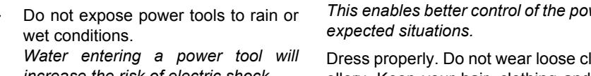
Disconnect the plug from the power source and/or the battery pack from the power tool before making any adjustments, changing accessories, or storing power tools.
Such preventive safety measures reduce the risk of starting the power tool accidentally.
Store idle power tools out of the reach of children and do not allow persons unfamiliar with the power tool or these instructions to operate the power tool.
Power tools are dangerous in the hands of untrained users.
Maintain power tools. Check for misalignment or binding of moving parts, breakage of parts and any other condition that may affect the power tools operation. If damaged, have the power tool repaired before use.
Many accidents are caused by poorly maintained power tools.
Keep cutting tools sharp and clean.
Properly maintained cutting tools with sharp cutting edges are less likely to bind and are easier to control.
Use the power tool, accessories and tool bits etc. in accordance with these instructions and in the manner intended for the particular type of power tool, taking into account the working conditions and the work to be performed.
Use of the power tool for operations different from those intended could result in a hazardous situation.
Service

Have your power tool serviced by a qualified repair person using only original spare parts.
This will ensure that the safety of the power tool is maintained.
Machine-specific SafetyWarnings

Wear hearing protection.
The effects of noise can cause loss of hearing capacity.

Operate the machine only with the auxiliary handle
Loss of control can cause personal injury.
Always assume a safe standing position and hold the power tool securely in both hands.
When the drill unexpectedly jams, the machine kicks back.
Hold the power tool only by the insulated gripping surfaces when performing an operation where the cutting tool may contact hidden wiring or its own power cord.
Contact with a "live" wire will also make exposed metal parts of the power tool "live" and lead to electric shock.

Secure the workpiece.
A workpiece clamped with clamping devices or in a vice is held more secure than by hand.
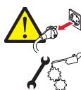
Do not work on stone containing crystalline silica (SiO2).
This will produce dust which is dangerous to your health.
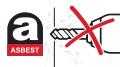
Do not work on materials containing asbestos.
Asbestos is considered carcinogenic!
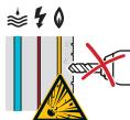
Take protective measures if there is danger of formation of combustible or explosive dust during operation that can be hazardous to health.
Example: Some dusts can be carcinogenic. Wear a dust mask and work with a dust/chip extraction unit, if possible to connect.
The tool must only be used with the appropriate guards fitted.
Always wait until the machine has come to a complete stop before placing it down.
The tool insert can jam and lead to loss of control over the power tool.
During operation, always ensure that the mains and extension cable is to the rear away from the device.
This prevents anyone from tripping over the cable while working.
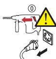
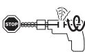
Move the switch to the "OFF" position before removing the plug from the plug socket.
When the tool is reconnected to the mains accidental starting of the machine is avoided, thus reducing the risk of accidents.

Tools not in use must be locked away safely in a dry place out of the reach of children.
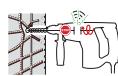
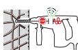
Use appropriate detectors to determine if utility lines are hidden in the work area or call the local utility company for assistance.
Contact with electric lines can lead to fire and electric shock. Damaging a gas line can lead to explosion. Penetrating a water line causes damage to property or electric shock.
Switch the power tool off immediately if the tool insert gets jammed. Be prepared for high torque levels if the tool kicks back.
The tool insert jams if:
the power tool becomes overloaded or
the tool tilts in the workpiece
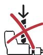
To mark the machine, do not drill into the housing.
The protective insulation would be bridged. Use stickers.
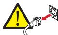
Never use the machine with a damaged cable. Do not touch the damaged cable and pull the mains plug when the cable gets damaged during operation.
Damaged cables increase the risk of electric shock.
Residual risk. Although this information sheet and the operating manuals for our electrical tools contain extensive instructions on safe working with electrical tools, every electrical tool involves certain residual risks that cannot be completely prevented through safety mechanisms. Therefore, electrical tools must always be operated with the necessary caution.
3. Device description

Read all the warnings and instructions before using the equipment.
Failure to follow the warnings and instructions may result in electric shock, fire and/or serious injury.
For help, please use the enclosed illustrations showing the device. Open these illustrations while reading the operating instructions.
Operating elements
I Drill chuck
II Drilling / percussion drilling changeover switch
III Gear selector switch (Option)
IV Reversing switch
V Stop button
VI On/Off control switch
VII Speed preselection setting dial (Option)
VIII Interlock button mains cable module
Device components
1 Tool holder
2 Additional handle
3 Depth stop
4 Mains cable module
5 Drill spindle
Scope of supply
See packaging
Specified conditions of use
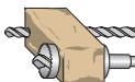
The percussion drill is intended for percussion drilling in brick, concrete and rock, and for drilling in wood, metal, ceramic and plastic. Devices with power control and clockwise/anticlockwise rotation are also suitable for fixing screws and thread cutting.
Requirements for the user
The tool must only be operated, maintained and serviced by authorised trained personnel. The personnel must be made aware of the relevant dangers.
Technical data

Mains voltage in V / Frequency in Hz Nominal power rating P in Watts

Noise levels

$$ L _ {p A} = A \text {- r a t e d n o i s e l e v e l} $$
$$ \mathrm {L} _ {\mathrm {w A}} = \mathrm {A} - \text {r a t e d n o i s e o u t p u t l e v e l} $$
$$ K = \text {M e a s u r e m e n t} $$
$$ \begin{array}{l} \text {T h e n o i s e l e v e l c a n e x c e e d 8 5 d B (A)} \ \text {d u n i n g o p e r a t i o n .} \end{array} $$
$$ \text {W e a r e a r p r o t e c h i o n} $$

Triaxial vibration emission level determined in accordance with EN 60745.
K = Measurement uncertainty value

The vibration emission level given in this information sheet has been measured in accordance with a standardised test given in EN 60745 and may be used to compare one tool with another.
The vibration emission level will vary because of the ways in which a power tool can be used and may increase above the level given in this information sheet. This could lead to underestimation of vibration when the tool is used regularly in such a manner.
Note: To be accurate, an estimation of the level of exposure to vibration experienced during a given period of work should also take into account the times when the tool is switched off and when it is running but not actually when doing the job.
This may significantly reduce the exposure level over the total working period.

1st n_0 = Idle speed (1st gear)
2nd n_0 = Idle speed (2nd gear)
1st n_1 = Load speed (1st gear)
2nd n_1 = Load speed (2nd gear)
in rpm

Number of impacts n^-1
Corner dimension in mm
Collar diameter in mm

Weight in kg
Drilling or percussion drilling in concrete - max. 0 in mm
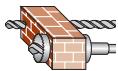
Drilling or percussion drilling in brick - max. in mm
Drilling or percussion drilling in sandstone - max. 0 in mm
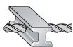
Drilling in steel - max. in mm
Drilling in aluminium - max. in mm

Fitting screws in wood - max. 0 in mm
Drilling in wood - max. in mm

Your power tool is double-insulated in accordance with EN 60745; For this reason an earth wire is not required.
The device is suppressed against radio and TV broadcasts, in accordance with EN 55014-1 and is immune to disturbances in accordance with EN 55014-2
4. Operation
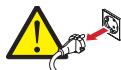
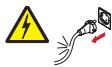
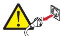
Before carrying out any work on the machine, pull the main plug.
EN
Putting into operation

Observe correct main voltage!
Before putting into operation, check that the mains voltage and frequency on the identification plate match the details of your mains supply.
Fit the additional handle
- Connect mains cable module if necessary

If using an extension cable: Only use extension cables specifically approved for the application with the required cross-section. Otherwise the power of the tool can be reduced and the cable can overheat. Replace damaged cables.
Additional handle

Operate the machine only with the additional handle
Loss of control can lead to injury.
Place the additional handle 2 in the working position to provide a safe and fatigue-free working situation.
Tighten the lower hand grip of the additional handle 2 by turning in clockwise direction. Turn the hand grip in anticlockwise direction to release it.
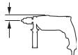
Depth setting
The required drilling depth X can be set by using the depth stop 3.
Release the additional handle 2 and insert the depth stop 3 into the additional handle.
Extend the depth stop 3 until the distance between the tip of the drill and the tip of the depth stop 3 corresponds to the required drilling depth X.
Mains cable
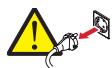
If the mains cable is damaged while working, pull the mains plug immediately.
Fixed power supply

Damaged mains cables must not be used. They must be replaced immediately by an expert technician.
Mains cable module

Mains cable module with Patent Quick Interlock.
Connect the mains cable module 4 to the handle. The plug must snap in.
Use the mains cable module 4 only for Kress power tools. Do not attempt to operate other machines with the module.
Damaged mains cable modules must not be used. They must be replaced by a new Kress mains cable module immediately.
Push the two unlocking buttons VIII and remove the mains cable module 4 from the handle.
Use only original Kress mains cable modules.
Safety friction clutch (Option)
To limit dangerous reaction torques, the machine is equipped with a safety friction clutch.
Always assume a safe standing position and hold the power tool securely in both hands.
When the drill becomes wedged unexpectedly, the power tool jerks.
If the drilling tool clamps or hooks, the drive to the drill spindle is interrupted and the noise of the unlocking coupling can be heard.
Remove the load from the machine immediately by retracting the drill.
Switch off the power tool and loosen the drilling tool if the power tool is blocked.
When switching on the machine with a jammed drilling tool, high reaction moments can occur.
Operation
On/off
Press or release the On/Off switch VI. The On/Off switch VI can be stopped with the stop button V. Release the On/Off switch VI by pressing and releasing briefly.

Make sure that the machine is not blocked longer than 2-3 seconds.
The motor can get damaged if blocked longer.
Preselect speed (Option)
In devices with a setting dial VII, you can select the speed using the setting dial VII depending on the area of application.
Position "A" = lowest speed
Position "G"= highest speed
or

$$ \begin{array}{l} = \text {l o w e s t s p e e d} \ = \text {h i g h e s t s p e e d} \ \end{array} $$
Change speed
The On/Off switch VI can be used for infinitely variable speed control. Light pressure on the On/Off switch VI causes the machine to rotate slowly; with increased pressure, the speed increases.

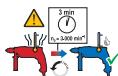
The motor can become overheated in case of continuous high load and low speeds. Allow motor to cool off at high speed in idle run.
Mechanical gear selection (option)
With the gear selector switch III you can preselect two speed ranges.
1 Low speed range, high torque; for drilling, fixing screws and thread cutting.
2 High speed range; for drilling and percussion drilling.

n≤ 1,698min^-1

The changeover must be done when the machine is running slowly.
-Note
The changeover must not be done at full load or maximum speed.
In this way, you can increase the life of your machine.
Select the direction of rotation
Operate the rotational direction switch IV only when the machine is at a standstill!
Grip the rotational direction changeover switch IV on both sides and set the required direction of rotation.

Clockwise rotation:
For drilling and fixing screws.

Anticlockwise rotation:
For loosening and removing screws and nuts.
Important: Press the rotational direction switch IV up to the stop on the housing, i. e. until it engages audibly.
The machine cannot be switched on if the reversing switch is in centre position.
Selecting the modes of operation
With the drilling / percussion drilling II changeover switch, you can switch the hammer mechanism on and off.
Drilling and fixing screws

Drilling and fixing screws
Percussion drilling

Percussion drilling
The changeover switch engages audibly and can be actuated when the machine is running.
-Note
Percussion drilling and drilling only in a clockwise direction!
Changing the tool
Disconnect the plug from the power source before making any adjustments, changing accessories, or storing power tools.
Such preventive safety measures prevent accidental start of the power tool.

Wear safety gloves for tool changing.
The tool insert can become very hot after working for long periods and/or the cutting edges of the tool insert are sharp.
Quick action chuck with ASL
The drill spindle stops if the On/Off switch is not pressed. This enables quick, convenient and easy changing of the insertion tool in the drill chuck.
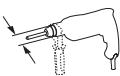
Mounting the tool
Turn the sleeve of the quick action drill chuck manually until you can no longer hear a "click". The drill chuck is locked automatically.
Removing the tool
Open the sleeve anticlockwise until the tool can be removed.
Toothed ring drill chuck
Mounting the tool
Insert tool. Fix the tool by turning at the toothed ring.
Insert the drill chuck wrench into one of the three holes on the toothed ring drill chuck and tighten clockwise.
Remove the drill chuck wrench.
Removing the tool
Open toothed ring drill chuck with drill chuck wrench and remove tool.
Remove the drill chuck wrench.
-Note
Do not fix drill chuck wrench on the drill with chains, strings or similar means.
The drill chuck wrench could get caught in moving parts and lead to injuries.
Screw tools
EN
When using screwdriver bits, always use a bit holder. Use only screwdriver bits that fit the screw head.
Position the drilling / percussion drilling II changeover switch to Drill.
Operating tips

Operate the machine only with the auxiliary handle
Loss of control can cause personal injury.
Always match the speed to the material concerned and the drill bit diameter.
Use high speeds when polishing and grinding.
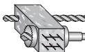
Percussion drilling

Wear protective glasses and hearing protection.
Drilling in tiles
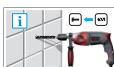
Start drilling a tile slowly. Only switch to percussion drilling when you have drilled through the tile.
This prevents the tile from cracking.
Drilling with diamond drill bits
Position the drilling / percussion drilling II changeover switch to Drill.
-Note
Switch off the hammer mechanism when drilling with a diamond drill bit.
Thread cutting
It is recommended to use machine screw taps.
Oil screw tap slightly.
Select low speed and 1st gear.
Cut in clockwise direction, stop, remove in anticlockwise direction.
-Note
Only work with low speed when thread cutting.
Preselect the required speed with the setting dial (Option).
To prevent the screw tap from breaking off.
5. Tools and accessories
For metal, use only flawless, sharpened drills; for stone and concrete, only rock drills with hard metal inserts.
Drill stands
For especially precise work, it is recommended to use a drill stand (accessory).
Changing the tool holder
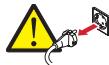
Before carrying out any work on the machine, pull the main plug.
All common drill chucks with 1/2'' x 20 UNF internal threads (13 mm max. chuck opening) can be used.
Observe the notes in the illustrations.
Removing the drill chuck
Place the power tool on a stable base.
Mount an Allen key in the drill chuck and fix a fork wrench on the drill chuck at the front. At the same time, fix a fork wrench on the wrench surface of the drive spindle.
Fix the drive spindle and loosen the drill chuck by turning the Allen key or fork wrench in an anticlockwise direction.
A tight drill chuck is loosened by tapping gently on the long shaft of the Allen key or fork wrench.
Remove the tools and unscrew the drill chuck completely.
Fitting the drill chuck
Clean thread on drill chuck and drill spindle.
Screw the drill chuck I onto the drill spindle 5.

The drill chuck must be tightened with a starting torque of 35-40 Nm.
6. Maintenance and Service
Maintenance and Cleaning
Before carrying out any work on the machine, pull the main plug.
Always keep the machine and ventilation slots clean.
- Wipe off the accessible plastic parts regularly with a cloth without cleaning agent.
Always keep the tool holder clean.
Cleaning the drill chuck
If using the percussion drill frequently, before use, hold the machine with the drill chuck vertically downwards and close and open the drill chuck across the entire clamping range. The collected dust falls out of the drill chuck hole.
Clean the clamping jaws and the clamping jaw holes regularly with cleaning spray.
Replacing brushes
Worn carbon brushes should be replaced by an authorised customer service organisation.
Service

After heavy use over a long period, the machine should be taken to a Kress service location for inspection and thorough cleaning.
The relevant service centres are listed in the enclosed appendix "SERVICE" or on the website www.kress-elektrik.de.
Spare parts / exploded view
Exploded views and spare parts lists are available on our home-page
www.spareparts.kress-elektrik.de
Environmental Protection

Recycle raw materials instead of disposing them as waste. The machine, accessories and packaging should be sorted for environmental-friendly recycling.
The plastic components are labelled for categorised recycling.

Only for EC countries.
Do not dispose of electric tools together with household waste material!
In observance of the European Directive 2002/96/EC for waste electrical and electronic equipment and its implementation in accordance with national law, electric tools that have reached the end of their life must be collected separately and returned to an environmentally compatible recycling facility.
Warranty
- This power tool has been carefully tested and has been subjected to a strict quality control process.
- We guarantee the free-of-charge repair of faults in the power tool that arise within 24 months from the date of purchase at the end user's premises and which can be attributed to a material or manufacturing defect. In certain countries there are special regulations concerning the warranty terms. We reserve the right to repair faulty components or to replace them. Replaced items become our property.
- Inappropriate use or handling and opening up the device by unauthorized repair centres leads to the warranty becoming void. The warranty does not cover: mechanical damage due to falls etc., damage caused by penetration of water or other fluids, cut and damaged cables, motor damage and mechanical damage caused by inappropriate overloading, wear parts e.g. carbon brushes, drill chucks, chuck keys, worn drilling spindles, motors, mains cables, batteries, saw blades, grinding discs, dust bags, accessories in general (drill bits, chisels etc.). Details of the various toll wear parts can be obtained from www.spareparts.kress-elektrik.de or from one of our service centres.
- The warranty may only be enforced when defects are reported without undue delay (including shipping damage). Warranty implementation does not extend the warranty period.
- If you need to apply the warranty, send the original purchase receipt together with the device to us or to the relevant service centre.
- The warranty obligations assumed by us shall exclude any further claims on the part of the buyer, in particular the right to cancellation of a sale, reduction and the assertion of damage claims.
- However, the buyer shall have the right to either a reduction (in the purchase price) or the cancellation of the sales agreement should we fail to eliminate any defects within a reasonable period of time.
- This does not exclude compensation claims in accordance with §§ 463, 480 Para. 2, 635 BGB caused by the failure of assured properties.
- The provisions defined in Items 7 and 8 only apply to the Federal Republic of Germany.

Technical modifications reserved
Durante el trabajo, el nivel acústicoSEOSEOSEOSEOSEOSEOSEOSEOSEOSEOSEOSEOSEOSEOSEOSEOSEOSEOSEOSEOSEOSEOSEOSEOSEOSEOSEOSEOSEOSEOSEOSEOSEOSEOSEOSEOSEOSEOSEOSEOSEOSEOSEOSEOSEOSEOSEOSEOSEOSEOSEOSEOSEOSEOSEOSEOSEOSEOSEOSEOSEOSEOSEOSEOSEOSEOSEOSEOSEOSEOSEOSEOSEOSEOSEOSEOSEOSEOSEOSEOSEOSEOSEOSEOSEOSEOSEOSEOSEOSEOSEOSEOSEOSEOSEOSEOSEOSEOSEOSEO SEO
Si se统计数据 a deteriorar el cable de red durante su uso. In general, the system is able to detect and eliminate all potential threats to the safety of the network.
Linea de alimentacion fija

Lineade alimentacion fija
Con el interruptor de conexión/defconexión VISEOSEOSEOSEOSEOSEOSEOSEOSEOSEOSEOSEOSEOSEOSEOSEOSEOSEOSEOSEOSEOSEOSEOSEOSEOSEOSEOSEOSEOSEOSEOSEOSEOSEOSEOSEOSEOSEOSEOSEOSEOSEOSEOSEOSEOSEOSEOSEOSEOSEOSEOSEOSEOSEOSEOSEOSEOSEOSEOSEOSEOSEOSEOSEOSEOSEOSEOSEOSEOSEOSEOSEOSEOSEOSEOSEOSEOSEOSEOSEOSEOSEOSEOSEOSEOSEOSEOSEOSEOSEOSEOSEOSEOSEOSEOSEOSEOSEOSEOSEO SEOEO SEOEO SEOEO SEOEO SEOEO SEOEO SEOEO SEOEO SEOEO SEOEO SEOEO SEOEO SEOEO SEOEO SEOEO SEOEO SEOEO SEOEO SEOEO SEOEO SEOEO SEOEO SEOEO SEOEO SEOEO SEOEO SEOEO SEOEO SEOEO SEOEO SEOEO SEOEO SEOEO SEOEO SEOEO SEOEO SEOEO SEOEO SEOEO SEOEO SEOEO SEOEO SEOEO SEOEO SEOEO SEOEO SEOEO SEOEO SEOEO SEOEO SEOEQ
- Symbols and abbreviations
- Symbols
- Kress
- -WARNING
- -NOTE-
- Safety rules
- General safety instructions for power tools
- WARNING!
- Work area
- Electrical safety
- Personal safety
- Power tool use and care
- Service
- Machine-specific SafetyWarnings
- Device description
- Operating elements
- Device components
- Scope of supply
- Specified conditions of use
- Requirements for the user
- Technical data
- Operation
- Putting into operation
- Additional handle
- Depth setting
- Mains cable
- Fixed power supply
- Mains cable module
- Safety friction clutch (Option)
- Operation
- On/off
- Preselect speed (Option)
- Change speed
- Mechanical gear selection (option)
- -Note
- Select the direction of rotation
- Clockwise rotation:
- Anticlockwise rotation:
- Selecting the modes of operation
- Drilling and fixing screws
- Percussion drilling
- Changing the tool
- Quick action chuck with ASL
- Mounting the tool
- Removing the tool
- Toothed ring drill chuck
- Screw tools
- Operating tips
- Drilling in tiles
- Drilling with diamond drill bits
- Thread cutting
- Tools and accessories
- Drill stands
- Changing the tool holder
- Removing the drill chuck
- Fitting the drill chuck
- Maintenance and Service
- Maintenance and Cleaning
- Cleaning the drill chuck
- Replacing brushes
- Spare parts / exploded view
- Environmental Protection
- Warranty
- Linea de alimentacion fija
Brand : KRESS
Model : 650 SBLR-1
Category : Electric drill