MC 6800 DSC - Communication Radio PRESIDENT - Free user manual and instructions
Find the device manual for free MC 6800 DSC PRESIDENT in PDF.
| Brand | PRESIDENT |
| Model | MC 6800 DSC |
| Product Type | Marine VHF Communication Radio with DSC |
| Dimensions (L x H x D) | 180 x 50 x 230 mm |
| Weight | 1680 g |
| Power Supply | DC 12 V (10.8 - 15.6 V) |
| Consumption | Transmit 5 A (25 W), Receive 0.3 A (standby), 0.9 A (max audio) |
| Frequency Band | Transmit: 156.025 - 157.425 MHz, Receive: 156.300 - 162.025 MHz |
| Output Power | 25 W (Hi) / 1 W (Lo) |
| Number of Channels | 55 international channels (1-28, 60-88 simplex & semi-duplex) |
| Emission Type | Voice: 16K0F3E, DSC: 13K5G2B |
| Main Functions | Digital Selective Calling (DSC), routine call, urgency, safety, group, distress alert, dual watch (DW), scan, memory scan, call register, MMSI directory (20 entries) |
| Display | LCD with indicators (M, D, S, DW, FS, MS, Hi/Lo, TX, RX, Mu, Sq, VL) |
| Backlight | 4 adjustable brightness levels |
| NMEA Input | NMEA0183 (position, date, time from GPS) |
| Antenna Connector | PL259 (50 Ω) |
| Audio Output | 3.5 W (external speaker 8 Ω), 2 W (internal speaker) |
| Included Accessories | Bracket, microphone hanger, screws, washers |
| Maintenance and Cleaning | Clean with a soft, dry cloth. Avoid solvents. Protect from moisture and extreme temperatures. |
| Safety | Do not expose to salt water. Install away from compasses (>1 m). Use a suitable 50 Ω antenna. |
| Spare Parts and Reparability | Contact an authorized dealer for MMSI replacement or repairs. |
| General Information | Complies with directive 1999/5/EC (R&TTE). DSC Class D. Marine use. |
Frequently Asked Questions - MC 6800 DSC PRESIDENT
User questions about MC 6800 DSC PRESIDENT
0 question about this device. Answer the ones you know or ask your own.
Ask a new question about this device
Download the instructions for your Communication Radio in PDF format for free! Find your manual MC 6800 DSC - PRESIDENT and take your electronic device back in hand. On this page are published all the documents necessary for the use of your device. MC 6800 DSC by PRESIDENT.
USER MANUAL MC 6800 DSC PRESIDENT
Inter-modulation ≥65 dB
| CHANNELS INS-5 20 01/00:30 S K Hi Mu |
- INTRODUCTION 36
2.FRONT PANEL DESCRIPTION 36 - LCD DISPLAY CHARACTERS 37
-
FIST MIKE/CONTROLLER 38
5.SENDING A CALL 39 -
Routine Call 39
- Urgency Call and Safety Call 39
- Group Call 40
-
Distress Alert 40
-
RECEIVING A CALL 41
-
Routine Call 41
- Urgency Call and Safety Call 41
- Group Call 42
-
Distress Alert 42
-
ADDITIONAL FUNCTIONS AND CONFIGURATION 42
-
Call Log 42
- Set MMSI of the radio 43
- Set Group ID 43
- Set Date and Time 43
- Set Manual Position 44
- Set call channels 44
-
Set called MMSI and vessels name 45
-
TECHNICAL SPECIFICATIONS 46
-
Receiver 46
- Channel 70 Monitor General specification 46
-
Transmitter 46
-
INSTALLATION 47
-
The Set Installation 47
- Electrical Installation 47
- Antenna Installation Recommendations 48
- Interfacing via NMEA 49
- Accessories 49
10.INTERNATIONAL VHF MARINE CHANNEL CHART 66
1. INTRODUCTION
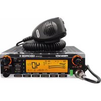
The MC 6800 DSC is a class D Digital Selective Calling (DSC) VHF marine radio.
It includes a VHF marine radio and a DSC controller in one set, therefore it is very convenient for use. The MC 6800 DSC support the latest GMDSS requirements for non-SOLAS vessels from the International Maritime Organization (IMO). It will enable you to make digitally selected calls, which are quicker and simpler to make then conventional voice calls using channel 16. Should distress situation occur, with the MC 6800 DSC you can quickly raise an alert, indicating your identity, your position and automatically establish distress communication on the emergency voice channel.
Groupe President Electronics operates a policy of continual development and reserves the right to alter and improve the specification of their products without notice.
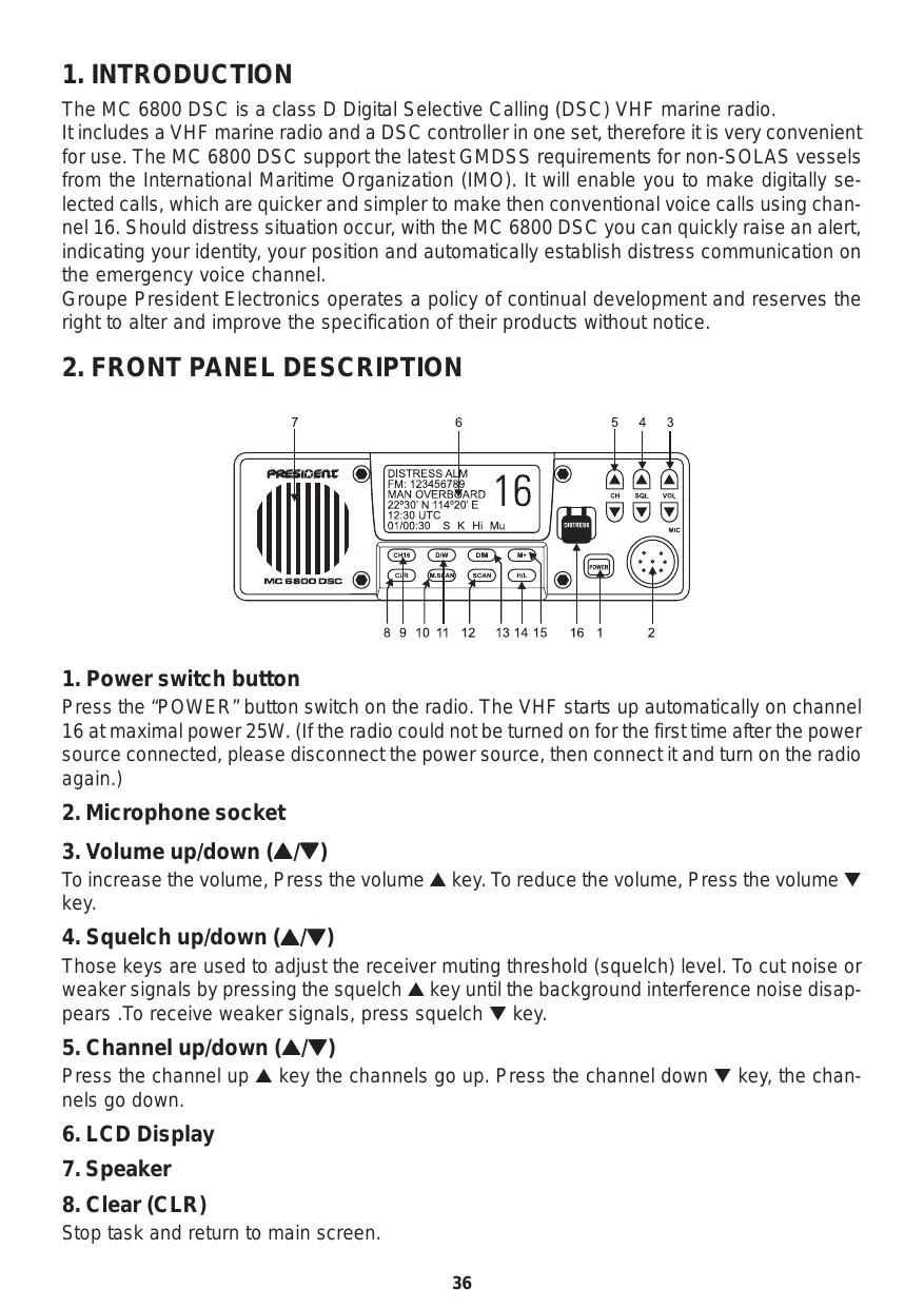
2. FRONT PANEL DESCRIPTION
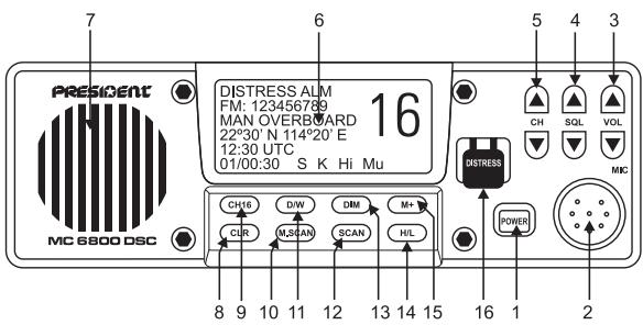
1. Power switch button
Press the "POWER" button switch on the radio. The VHF starts up automatically on channel 16 at maximal power 25W. (If the radio could not be turned on for the first time after the power source connected, please disconnect the power source, then connect it and turn on the radio again.)
2. Microphone socket
3. Volume up/down ( /)
To increase the volume, Press the volume key. To reduce the volume, Press the volume key.
4. Squelch up/down ( /)
Those keys are used to adjust the receiver muting threshold (squelch) level. To cut noise or weaker signals by pressing the squelch key until the background interference noise disappears. To receive weaker signals, press squelch key.
5. Channel up/down (▲/▼)
Press the channel up key the channels go up. Press the channel down key, the channels go down.
6. LCD Display
7. Speaker
8. Clear (CLR)
Stop task and return to main screen.
9. Channel 16 (16)
It will automatically select channel 16 on high transmission power when pressed. Any function active (Dual watch, scanning etc.) will be cancelled.
10. and 12. Scan (SCN)/Memory scan (M.SCN)
This function scans through each channel sequentially until a signal above the squelch level set is detected. Once the signal ends or drops below the squelch level set, the radio will continue scanning. Press "SCN" or "M.SCN" to enter scan mode, the LCD will show "FS"(Full scan) or "MS"(Memory scan) on the bottom right of the LCD screen.
Note that the radio will not transmit, nor will alternate channels be able to be selected while in scan mode. To restore normal operation, either press "SCN" or "CLR" again. Press "16" the radio will restore normal operation and will select channel 16.
The memory scan operates in the same way as the scan, except that it will only scan channels that have been entered into the scan memory. If no channel has been entered into the memory then this function will not be available.
11. Dual watch (DW)
Dual watch enables the radio to scan between the selected channel and priority channel (CH16), To activate dual watch mode select the channel and press "DW" key, the "DW" legend will be displayed on the bottom right of the LCD.
Note that the radio will not transmit, nor will alternate channels be able to be selected while in dual watch mode. To restore normal operation, either press "DW", "CLR". Press "16" the radio will restore normal operation and will select channel 16.
13. Backlighting (DIM)
There are four steps of brightness levels. When power of the Radio is switched on, the backlighting is brightest.
The LCD backlighting is controlled by pressing "DIM" button.
14. RF High or Low Output Power (H/L)
This "H/L" button operates as a toggle switching between 1W and 25W.
When RF output power is set at 1W or 25W, the "Lo" or "Hi" symbol will show at bottom right of the LCD screen.
Note that some channels are restricted to 1W transmit power. The radio is programmed to switch to low power automatically when one of these channels is selected.
15. Channel Memory Function (M+)
The function of this key will add the currently selected channel into the scan memory. Press the "M+" key the LCD display will show "M" on the bottom right of the LCD display, indicating that the channel has been entered into the scan memory. Press the "M+" key again if the channel is already in the memory, the "M" will be deleted indicating that the channel is not a memory scan channels.
16. Distress call button with a safety guard
3. LCD DISPLAY CHARACTERS
The meaning of characters on the button right of the LCD display are as follows:
M Indicate the displayed channel is the memory-scanning channel
D Indicates the displayed channel is duplex channel
S Indicates the dis played channel is simplex channel
DW Indicates Dual watch scanning operation
FS Scans every channels of current channel list
MS Scans the memory channels
Hi Indicates the TX maximum output power is 25W
Lo Indicates the TX maximum output power is 1W
TX Indicates the Radio is in transmit
RX Indicates the Radio is in reception
Mu Appears when the squelch opens
Sq Squelch control is activated; the Bar indicates the level of the squelch signal
VL Volume control is activated, the Bar indicates the audio output level
The fist mike/controller have mike, PTT switch, Soft-keypad and distress Call button with the safety guard .The telephone style ITU keypad is used for entering numeric data. When required, the keys will automatically switch to character mode allowing letters, numbers and punctuation characters to be entered. Repeatedly pressing a key will cycle through the characters available on that key.
| 1 press | — | A | D | G | J | M | P | T | W | 0 |
| 2 presses | , | B | E | H | K | N | Q | U | X | ( |
| 3 presses | . | C | F | I | L | O | R | V | Y | ) |
| 4 presses | / | ? | ! | : | ” | , | S | & | Z | % |
| 5 presses | 1 | 2 | 3 | 4 | 5 | 6 | 7 | 8 | 9 | 0 |
The other keys are as follows:
MENU Select menu item.
ENT Confirm the action.
CLR Stop task and return to remain screen or return to the last screen.
CALL Selects Call item.
DIST Distress Call button with a safety guard.
/ Press it to raise or lower the working channel. And it can select the stored working channels.
/ Move the cursor position when setting. And it can view next or last message and select next or last item.
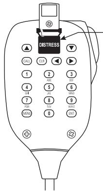
Distress button cover
5.SENDING A CALL
Making a DSC call is very simple. First, choose the call type (Routine, Safety, Urgency, Group or Distress Alert). If required, enter the destination and working channel and then send the call by pushing "ENT". The digital signal will be sent out in under a second, containing the vessels ID and the call type.
To order for the Radio to function, your MMSI (Maritime Mobile Service Identifier) number will need to be entered. For the Group call, the group ID will need to be entered too.
1. Routine Call
To make a routine call, press "CALL" key on the fist mike/controller keypad to select Routine call .The screen is as below.
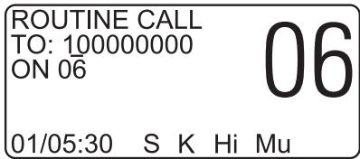
Then enter a called vessel's MMSI number with the keypad and select a working channel by pressing the or key on the keypad from the channel list.
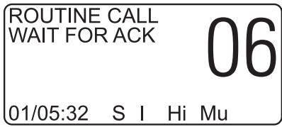
Press "ENT" the Radio will send a routine call. Then the radio will change to following interface and waiting for a replay. When the reply is received, it will sound a tone and automatically set to the selected working channel. A voice call can then be made in the normal way.
2. Urgency Call and safety Call
Press "CALL" key on the fist mike/controller keypad to select safety call or urgency call as follow figure.

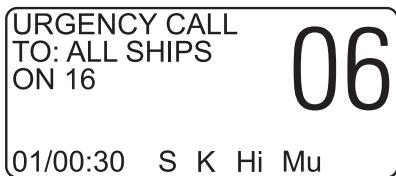
Both urgency and safety calls are all ships calls. You may use the or keys to select a different working channel when making safety call. Urgency calls always use channel 16. Press the "ENT" key, the figure is as follows.
| SAFETY CALL SURE SEND? | 06 |
| 01/00:31 | S K Hi Mu |
| URGENCY CALL SURE SEND? | 06 |
| 01/00:31 S K Hi Mu | |
Press the "ENT" key again to make the call. When the call is sent, the radio will be set to the working channel. Allow a few seconds for the stations receiving the call to switch to the working channel. Then make a normal voice call on the selected working channel.
3. Group Call
If a group ID has been set up for the Radio. A call can be made to other members of the group.
Press the "CALL" key on the keypad to select the group call screen as follows.
| GROUP CALL TO: 023456789 ON 06 | 06 |
| 01/00:30 S I Hi Mu | |
Select a working channel from the channel list by pressing the or keys on the keypad. Press "ENT" to send the call, allow a few seconds for the other members of the group to reach the radios (all VHF radios in the group should automatically switch to the selected working channel upon acknowledgement), then make a normal voice call using the working channel.
4. Distress Alert
Turn away the protective cover and press "DIST" key on the fist mike or on radio. The Distress Alert screen will be displayed as follows.
| DISTRESS ALM MAN OVERBOARD 22°30' S 114°20' E 12:30 UTC 01/00:30 S I Hi Mu |
If time permits, press the or keys to select the nature of the distress. There are 10 categories recognized as Distress Alert situations. Which are - fire, flooding, collision, grounding, listing, sinking, adrift, abandoning, piracy and man overboard. There is also a default undesigned category, which is used if no category is selected here.
Press and hold the "DIST" key for about five seconds. An alarm will sound and a countdown to the transmission will be displayed.
The Distress Alert transmission contains the following data:
The vessel's MMSI;
- The vessel's position (either from the NMEA0183 input, or manually entered);
The time (from NMEA or manual);
The nature of the distress.
After the Distress Alert has been sent, the Radio will automatically tune to channel 16 and the Radio will repeat the Alert approximately every four minutes until either an acknowledgement
is received, or "CLR" is pressed (it is not recommended that the Distress Alert is cancelled manually by pressing "CLR" unless you are requested to do so by the rescue authorities).
While the Distress Alert remains active, an intermittent alarm will continue to sound about one time per 15s.
When an acknowledgement is received from the Rescue Co-ordination Center, this will cancel the Distress Alert transmission from the Radio and automatically switch the Radio to the required working channel. The subsequent Rescue Co-ordination will be performed using the voice working channel.
6. RECEIVING A CALL
When a DSC call is received, the radio will switch to the call log screen to display the details of the call and ring or sound the alarm depending on the nature of the call. The procedures that follow describe how to handle the types of calls that can be received.
1. Routine Call
When a Routine call is received, the screen will show the details of the call, which it is from and working channel as follows, and an alarm will sound.
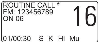
Press the "ENT" key on the fist mike keypad, an acknowledgement will be sent to caller and the radio will be automatically switched to working channel for normal voice communication. The **will disappear when the call has been acknowledged..
When looking back at routine call logs, if there is a “” symbol on the screen, you can press directly “ENT” key to send an acknowledgement. After acknowledgement, the “” will disappear.
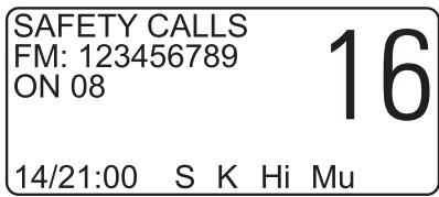
2. Urgency Call and Safety Call
The procedures for urgency and Safety calls are very similar, an urgency call will sound the distress alarm and switch the radio to Channel 16.

A safety call will sound a normal ring and switch the radio to the specified working channel as follows.
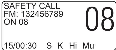
Press the "ENT" key to stop the ringing, and then listen for the voice message.
3. Group Call
When a Group call is received, the radio will sound a ringing and display the details of the call, indicating whom it is from and the working channel as follows.
| GROUP CALL FM: 132456789 ON 08 | 16 |
| 15/00:30 S K Hi Mu | |
Press "ENT" key to stop the ringing, then listen for the voice message or speak.
4. Distress Alert
If a Distress Alert or a Distress Relay is received from another vessel, an alarm will sound and the Radio will switch to channel 16, The screen will show the details of the Distress Alert or Distress Relay, the MMSI of the vessel, the nature of the distress, it's position and time, Mute the alarm by pressing "ENT" Key and maintain a listening watch on channel 16 for the distress message. Press "CLR" key to clear the display.
| DISTRESS ALM FM: 123456789 MAN OVERBOARD 22°30' N 114°20' E 12:30 UTC 01/00:30 S K Hi Mu |
| ALERT RELAY FM: 112233445 ID: 123456789 22°30' N 114°20' E 12:30 UTC 01/00:30 S K Hi Mu | 16 | |
7. ADDITIONAL FUNCTIONS AND CONFIGURATION
In order to access additional functions, Press "MENU" key of fist mike.
1. Call Log
The call log can be used to look back through the previous received call logs, the most recent call first.
Press "MENU" soft key to select the "LOG VIEW" screen. If there is no any message have been received, the screen will be as follows.
| LOG VIEW : NO ITEM !! | 16 |
| 15/11:30 | S K Hi Mu |
If a message has been received, the screen will be as follows:
| 19 CALL LOGS PRESS OR TO VIEW | 16 |
| 15/11:30 S K Hi Mu | |
The or soft key are used to move back and forward through the log. The bottom left of the screen shows the date time of receiving the call in dd/HH/mm as follows:
Press "CLR" key to exit from the call log screen.
2. Set MMSI of the radio
In order for the Radio to function, your MMSI (Maritime Mobile Service Identifier) number will need to be entered.
Press "MENU" key to select the "MMSI VIEW" screen as follows and then press numeric soft key enter the MMSI numbers (9 numbers).
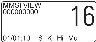
This number can be obtained from your local radio communications authority. If a mistake is made, use the or key move back and edit the error. Then press ^ ENT" key, the Radio will ask for verification. It is important that the MMSI entered is checked carefully, as it can only be entered once!
Then press "ENT" once again to confirm the entered.
To change the MMSI number after it has been programmed the unit must be returned to an authorized dealer to erase the existing number.
3. Set Group ID
To enter a Group ID (if for example, the vessel is part of a flotilla or fishing fleet etc.), press "MENU" key to select the "GROUP ID" screen as follows:
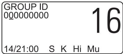
Use the keypad to enter the Group ID and press "ENT" to accept, Pspress "CLR" key to exit to the main screen. Note that the first number must be "0".
4. Set Date and Time
Normally, the date and time is supplied by the NMEA0183 navigational input (from a GPS etc). If a navigator is not connected, or the signal has been lost, the missing data can be manually entered here.
Press "MENU" to select "DATE/TIME" screen as follows, Use the keypad to enter date and time. Press "ENT" key to accept the date and time.
| DATE/TIME DD/MM/YYYY 01/01/0000 HH:MM 00:01 01/00:01 S K Hi Mu |
Note that the time should be UTC (GMT) and entered in 24 hours clock format.
5. Set Manual Position
If the position of the vessel cannot be obtained from a navigator via the NMEA0183 input, this date can be entered manually. Press "MENU" key to select the "POSITION/UTC" screen as follows, and then use the keypad to enter the required data as follows.
| POSITION/UTC 99°99'S 999°99"W 88:88 UTC | 16 |
| 01/00:30 S K Hi Mu |
Press "ENT" key to accept the position and time entered.
If no data is being received from the NMEA input, a "!" symbol will appear on the main screen, and will flash 4 hours later after the last position was input and prompt the operator to enter the current position. After 23 hours, if the radio has not received any position data either manually or from the UMEA input, then the position data will disappear from the screen, and it will show "NO POSITION" if a Distress Alert is transmitted.
6. Set call channels
The Radio includes a list of 9 working channels, which can be scrolled through when using the Routine, Safety or Group Calling. The first four channels are preset as 06, 08, 72 and 77. These cannot be amended. The remaining five channels are programmable. Press "MENU" key to select "CHANNELS" screen ssas follows.
| CHANNELS INS DEL | 16 |
| 01/00:30 S K Hi Mu | |
Always consult your local authority requirements when choosing suitable working channels. Be aware of which channels are Duplex and will not allow ship to ship communication. Use or key to select inserting or deleting channel screen, then press "ENT" key for enter. The "CHANNELS-INS" screen is as follows (insert the 5th channel):
| CHANNELS INS-5 20 | ||
| 01/00:30 | S | K Hi Mu |
Press or key to change the selected channel, and press "ENT" key for acceptance. Then press or keys to enter next channel. Press "CLR" key to return to the main screen. If want to delete a channel, press "MENU", or and "ENT" keys again to select "MENUDEL" screen as follows:
| CHANNELS DEL-7 67 16 | 16 |
| 01/00:30 S K Hi Mu | |
Press or key to select channel (the 5th « the 9th) that is wanted to be deleted, then press "ENT" key for confirmation.
7. Set called MMSI and vessels name
The Directory screen is used to add, edit and delete entries from a list of up to 20 stored MMSI numbers, which can be recalled in the Routine call screen.
To access the directory function, press menu in the main "DIRECTORY" screen as follows.
| DIRECTORY EDIT DEL ▲ ADD | 16 |
| 01/00:30 S K Hi Mu | |
To create a new entry, press or keys to move symbol nearby "ADD", then press "ENT" key to enter Directory-add screen as follows.
| DIRECTORY ADD-4 | 16 |
| 00000000 | 01/00:30 S K Hi Mu |
Use the keypad to enter a name and number, and use the keys to move backwards and forwards along the line.
When the name and number have been entered, press "ENT" to enter the name and MMSI. To edit an existing entry, press or key to move symbol on the screen nearby "EDIT", then press "ENT" key to enter Directory-edit screen as follows.
| DIRECTORY EDIT-1 SIMDN 123456798 01/00:30 S K Hi Mu |
Use the or key to select the number of the entry, then press "ENT" key.
Use the or key to move along the name and MMSI fields, using the keypad to edit the date. Press "ENT" to store the modified entry.
To delete an entry, press or key to move symbol on the screen nearby "DEL", then
press "ENT" key to enter Directory-DEL screen as follows.
Use the or key to select the number of the entry, the press "ENT" key to delete the entry.
8. TECHNICAL SPECIFICATIONS
Power supply
DC 12 V +30/-10%
Channel capability
55 international channels
1~28, 60~88 simplex & semi-duplex
Frequency Resolution
25 KHz
Method of frequency generation
synthesizer
Dimension
180(W) x 50(H) x 230(D) mm
Weight
1680 g
1. Receiver
Multi Channel Receiver
The receiver incorporates a dual conversion super-heterodyne design.
Tuning frequency range
156.300-162.025 MHz
IF frequency used:
21.4 MHz; 455 KHz
Maximum useable sensitivity
≤ 6 dBu e.m.f. of 20 dB/SINAD
Adjacent Channel selectivity
≥70 dB
Inter-modulation Rejection
≥68 dB
Current:
0.9 A (Max Audio)
Audio Frequency Response
0.3 A (STBY)
Hum and Noise
+1, -3 dB of +6 dB/octave
Audio output
De-emphasis 300-3000 Hz
≤40 dB
3.5 W at less than 10% distortion
with 8 Ohm external speaker
2 W only internal speaker
2. Channel 70 Monitor General specification
Frequency
CH70 (156.525 MHz)
Sensitivity
≤ 0 dBμ e.m.f. for 20 dB/SINAD
Band width
16 KHz
First IF frequency used
17.9 MHz
Second IF frequency used
455 KHz
Adjacent Channel Selectivity
≥70 dB
Inter-modulation Rejection
≥65 dB
Mode of Reception
16K0G2B
3. Transmitter
Type of emission
16K0F3E(Voice)
13K5G2B(DSC)
Frequency range
156.025 - 157.425 MHz
Output power
25 W, 1 W into 50 Ohms
Audio Harmonic Distortion
≤10%
Audio Frequency Response
+/-3 dB of +6 dB/octave
Hum and Noise
Pre-emphasis 300 - 3000 Hz
Frequency Deviation
≤-40 dB
Spurious Emissions (Radiated)
5 KHz max peak
Current
≤ 0.25 W
5 A (25 W)
9. INSTALLATION
1. The Set Installation
The radio should be sited so that engine noise and vibration or other background noise does not make it difficult for the operator to hear.
It is recommended that it is not installed where it will be exposed to continuous direct sunlight, as this will eventually damage the LCD display.
As microphones and loudspeakers contain powerful magnets, the radio should not be installed within 1m (3ft 3in) of any compasses, whether magnetic or electronic.
The fins on the back of the case act as a heat sink to dissipate heat generated by the set when in use, which maintains the high efficiency of the radio. The free circulation of air is essential - if mounting the radio in an enclosed space ensure that the space is vented.
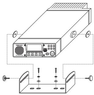
The MC 6800 DSC Radio is supplied with a reversible mounting bracket. This can be used to mount the radio on the chart table or on an overhead bulkhead (Fig A). The bracket is fixed in place using four screws (supplied). Before installing, ensure that there is at least 88mm(3.5 in) verticals clearance and 127mm (5in) horizontal clearance behind the bracket to allow the radio to fit (Fig B). The rake angle of the radio can be adjusted by slackening the clamp.
Desktop mounting Overhead mounting
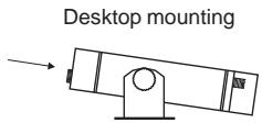
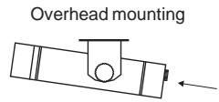
Fig A
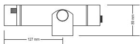
Fig B
Mounting on dashboard
Fig C
2. Electrical Installation
The MC 6800 DSC Radio has four electrical connections – the handset/fistmike socket is on bottom right of the front panel. On the bottom right of the back of the case there are three flying leads – the first is DC power cord (the red wire is positive, black is negative.), the second is speaker cord (the black wire is ground), the final is the GPS interface cord (the Brown wire is Ground).
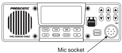
Fig D
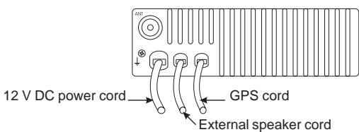
Fig E
The MC 6800 DSC requires a 12v DC supply to operate, This lead should be connected to the vessel's power supply, keeping the cable runs as short as possible. Although the radio draws very little current when receiving, a heavier current is drawn when transmitting which may result in a voltage drop if very long cable runs are used of inadequate core diameter. If the supplied power lead is not long enough, an extension of up to 3m(10ft) can be made using at least 2.5mm (13AWG) wire.
The chassis of the Radio is not connected to either supply rail. This allows a direct connection to the ship's earth connection for voltage and RF interface protection. The red wire is positive and black is negative. If polarity is accidentally reversed, the set will not operate.
The antenna is connected to the radio using a standard PL259 type connector as fitted to most marine antennae. If fitting to an existing antenna, check that the contacts are not corroded before connecting, as this will affect the quality of the signal, Ensure that the retaining collar of the antenna plug is securely tightened to prevent accidental disconnection.
3. Antenna Installation Recommendations
The most important factor in the performance of the MC 6800 DSC radio will be the quality and positioning of the antenna. Most recorded problems with VHF radios are related to poor antenna siting, faulty cabling, poor quality cable joints and low voltage supply. Therefore, if replacing an existing if installation, it is important that these factors are checked when installing the radio.
As the range of VHF signals are governed by line of sight, the antenna should be placed as high as possible, while remaining clear of any metallic objects that could influence the radiation of the antenna.
The most popular antennae for marine use are 1m(3ft 3in) long. On sail boats these are usually mounted on the masthead, where the length of the antenna keeps it clear from the navigation lights and wind vanes etc. This type of antenna can also be mounted on the cockpit roof or garage of powerboats.
Longer whip antennae are recommended for larger boats. These radiate the same total power as smaller antennae, but concentrate it into a narrower beam, which is advantageous on a tall mast at extreme range where concentrating the available power into a narrow horizontal beam becomes more important. However, if the antenna is mot vertical when transmitting, the beam will be angled either too high or too low (Fig G). Here the wider beam of the shorter antenna will be more universally effective, although the signal will be weaker (Fig F):
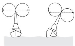
Fig F
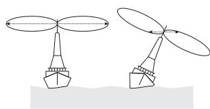
Fig G
Therefore vessels with a large heel angle (small sailboats) would be better choosing a short masthead antenna. Your local agent should be able to provide specific advice on antenna choice for the vessel it is to be fitted to.
The antenna coaxial cable and any connectors used must be rated at 50_1^1 . Under no circumstances should standard domestic TV cable and connectors be used. Incorrectly rated cables and connectors could result in power not reaching the antenna, but also power could be reflected back into the radio, damaging it in the process.
4. Interfacing via NMEA
The MC 6800 DSC Radio incorporates an internal NMEA0183 processor which is used to provide position, date and time data from an external navigator – ideally a GPS.
The Radio can process NMEA0183 version 2.0 sentences RMC, GGA, GLL and ZDA, either of which will provide the necessary data.
Brown : NMEA Data OUT (+)
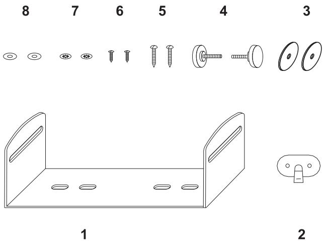
- Mounting Bracket 1 5. Mounting Screws 2
- Microphone hanger 1 6. Mic hanger Screws 2
- Rubber washers 2 7. Flat washers 2
- Mounting Bracket Knobs 2 8. Spring washer 2
INHALTSANGABE
- EINLEITUNG 51
2.BEDIENFELD 51 - ZEICHEN DER LCD-ANZEIGE 52
- HAND-MIKROFON/TASTENFELD 53
-
SENDEN 54
-
"Routine Call" 54
- "Urgency Call and Safety Call" 54
- "Group Call" 55
-
"Distress Alert" 55
-
EMPFANGEN 56
-
"Routine Call" 56
- "Urgency Call and Safety Call" 56
- "Group Call" 57
- "Distress Alert" 57
7.ZUSATZLICHE FUNKTIONEN UND KONFIGURATIONEN 57
2. "Urgency Call and Safety Call"
2. "Urgency Call and Safety Call"
6. Set call channels
| Channel | Transmitter Frequency | Receiver Frequency | Mode S/D | Channel Assignment | Function | |
| Ship To Ship | Ship To Shore | |||||
| 1 | 156.050 | 160.650 | D | Public Correspondence, Port Operation | YES | YES |
| 2 | 156.100 | 160.700 | D | Public Correspondence, Port Operation | YES | YES |
| 3 | 156.150 | 160.750 | D | Public Correspondence, Port Operation | YES | YES |
| 4 | 156.200 | 160.800 | D | Public Correspondence, Port Operation | YES | YES |
| 5 | 156.250 | 160.850 | D | Public Correspondence | YES | YES |
| 6 | 156.300 | 156.300 | S | Safety (Compulsory) | YES | NO |
| 7 | 156.350 | 160.950 | D | Port Correspondence, Port Operation | YES | YES |
| 8 | 156.400 | 156.400 | S | Commercial, inter-ship | YES | NO |
| 9 | 156.450 | 156.450 | S | Commercial/Non-Commercial | YES | YES |
| 10 | 156.500 | 156.500 | S | Commercial | YES | YES |
| 11 | 156.550 | 156.550 | S | Commercial, VTS | YES | YES |
| 12 | 156.600 | 156.600 | S | Port Operation, VTS | NO | YES |
| 13 | 156.650 | 156.650 | S | Bridge to Bridge,(1W) navigational | YES | YES |
| 14 | 156.700 | 156.700 | S | Port Operation, VTS | YES | YES |
| 15 | 156.750 | 156.750 | S | Recv Only-Coast to Ship | YES | YES |
| 16 | 156.800 | 156.800 | S | Calling&Safety, Compulsory | YES | YES |
| 17 | 156.850 | 156.850 | S | State Controlled Ship to Coast (1W) | YES | YES |
| 18 | 156.900 | 161.500 | D | Port Operation | YES | YES |
| 19 | 156.950 | 161.550 | D | Port Operation | NO | YES |
| 20 | 157.000 | 161.600 | D | Port Operation | NO | YES |
| 21 | 157.050 | 161.650 | D | Public Correspondence | NO | YES |
| 22 | 157.100 | 161.700 | D | Public Correspondence | NO | YES |
| 23 | 157.150 | 161.750 | D | Public Correspondence | NO | YES |
| 24 | 157.200 | 161.800 | D | Public Correspondence | ||
| 25 | 157.250 | 161.850 | D | Public Correspondence | ||
| 26 | 157.300 | 161.900 | D | Port Operation,VTS | ||
| 27 | 157.350 | 161.950 | D | Public Correspondence, Port Operation | ||
| 28 | 157.400 | 162.000 | D | Public Correspondence, Port Operation | ||
| 60 | 156.025 | 160.625 | D | Public Correspondence, Port Operation | ||
| 61 | 156.075 | 160.675 | D | Public Correspondence, Port Operation | ||
| 62 | 156.125 | 160.725 | D | Public Correspondence, Port Operation | ||
| 63 | 156.175 | 160.775 | D | Public Correspondence, Port Operation | ||
| 64 | 156.225 | 160.825 | D | Public Correspondence, Port Operation | ||
| 65 | 156.275 | 160.875 | D | Public Correspondence, Port Operation, VTS | YES | YES |
| 66 | 156.325 | 160.925 | D | Public Correspondence, Port Operation | YES | YES |
| 67 | 156.375 | 156.375 | S | Non-Commercial, VTS | YES | NO |
| 68 | 156.425 | 156.425 | S | Non-Commercial | YES | YES |
| 69 | 156.475 | 156.475 | S | Non-Commercial | YES | YES |
| 70 | 156.525 | S | DSC Distress, urgency, safety and calling | YES | NO | |
| 71 | 156.575 | 156.575 | S | Intership, Port Operation, on Commercial | YES | YES |
| 72 | 156.625 | 156.625 | S | Non-Commercial | YES | NO |
| 73 | 156.675 | 156.675 | S | Port Operation, VTS | YES | YES |
| 74 | 156.725 | 156.725 | S | Port Operation, VTS | YES | YES |
| 77 | 156.875 | 156.875 | S | Intership, Port Operation | YES | NO |
| 78 | 156.925 | 161.525 | D | Port Operation, Public Correspondence | YES | YES |
| 79 | 156.975 | 161.575 | D | Port Operation, Public Correspondence | YES | YES |
| 80 | 157.025 | 161.625 | D | Port Operation, Public Correspondence | YES | YES |
| 81 | 157.075 | 161.675 | D | Port Operation, Public Correspondence | YES | YES |
| 82 | 157.125 | 161.725 | D | Port Operation, Public Correspondence | YES | YES |
| 83 | 157.175 | 161.775 | D | Port Operation, Public Correspondence | YES | YES |
| 84 | 157.225 | 161.825 | D | Public Correspondence | YES | YES |
| 85 | 157.275 | 161.875 | D | Public Correspondence | NO | YES |
| 86 | 157.325 | 161.925 | D | Public Correspondence | NO | YES |
| 87 | 157.375 | 161.975 | D | Public Correspondence | NO | YES |
| 88 | 157.425 | 162.025 | D | Port Operation, Public Correspondence | NO | YES |
Déclaration DE CONFORMITE DECLARATION DE CONFORMIDAD CERTIFICATE OF CONFORMITY KONFORMITÄTSERKLÄRUNG
Nous, GROUPE PRESIDENT ELECTRONICS, Route de Sète, BP 100 - 34540 Balaruc - FRANCE,
Nosotros, GROUPE PRESIDENT ELECTRONICS, Route de Sète, BP 100 - 34540 Balaruc - FRANCIA,
We, GROUPE PRESIDENT ELECTRONICS, Route de Sète, BP 100 - 34540 Balaruc - FRANCE,
Wir, GROUPE PRESIDENT ELECTRONICS, Route de Sète, BP 100 - 34540 Balaruc - FRANCE,
is in conformity with the essential requirements of the Directive 1999/5/CE (Article 3) adapted to the national law, as well as with the following European Standards: