
LINCOLN - Radio transceiver PRESIDENT - Free user manual and instructions
Find the device manual for free LINCOLN PRESIDENT in PDF.
User questions about LINCOLN PRESIDENT
0 question about this device. Answer the ones you know or ask your own.
Ask a new question about this device
Download the instructions for your Radio transceiver in PDF format for free! Find your manual LINCOLN - PRESIDENT and take your electronic device back in hand. On this page are published all the documents necessary for the use of your device. LINCOLN by PRESIDENT.
USER MANUAL LINCOLN PRESIDENT
8) PA (Public Address):
8) PA (PUBLIC ADDRESS):
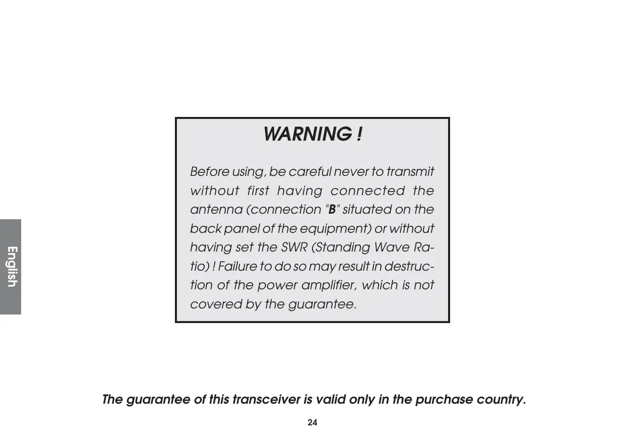
Before using, be careful never to transmit without first having connected the antenna (connection "B" situated on the back panel of the equipment) or without having set the SWR (Standing Wave Ratio)! Failure to do so may result in destruction of the power amplifier, which is not covered by the guarantee.
The guarantee of this transceiver is valid only in the purchase country.
Welcome to the world of the most sophisticated microprocessor controlled Amateur radios. This entirely new generation of PRESIDENT Amateur Radio will give you the most complete access to amateur radio communication. Introducing state-of-the-art technology for the most advanced features, this PRESIDENTLINCOLN is a new milestone in user friendliness and prompt response to the most demanding amateur. To assure you get the most enjoyment of all the features, please read this guide thoroughly before installing and operating your PRESIDENT LINCOLN.
A) INSTALLATION :
1) WHERE AND HOW TO MOUNT YOUR MOBILE RADIO :
a) You should choose the most appropriate setting from a simple and practical point of view.
b) Your radio should not interfere with the driver or the passengers.
MOUNTING DIAGRAM
c) Remember to provide for the passing and protection of different wires (e.g. power, antenna, accessory cabling) so that they do not in any way interfere with the driving of the vehicle.
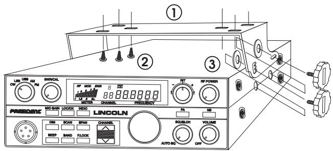
d) To install your equipment, use the cradle (1) and the self-tapping screws (2) provided (drilling diameter 3.2mm ). Take care not to damage the vehicle's electrical system while drilling the dash board.
e) Choose where to place the microphone support and remember that the microphone cord must stretch to the driver without interfering with the controls of the vehicle.
- N.B.: As the transceiver has a frontal microphone socket, it can be set into the dash board. In this case, you will need to add an external loud speaker to improve the sound quality of communications (connector (C) situated on the back panel). Ask your dealer for advice on mounting your radio.
2) ANTENNA INSTALLATION :
a) Choosing your antenna :
- For amateur radios, the longer the antenna, the better its results. Your dealer will be able to help you with your choice of antenna.
b) Mobile antenna :
- Must be fixed to the vehicle where there is a maximum of metallic surface (ground plane), away from windscreen mountings.
- If you already have a radio-telephone antenna installed, the antenna should be higher than this.
- There are two types of antenna: pre-regulated which should be used on a good ground plane (e.g. car roof or lid of the boot), and
adjustable which offer a much larger range and can be used on a smaller ground plane (see «How to Adjust SWR», page 27 § 5). - For an antenna which must be fixed by drilling, you will need a good contact between the antenna and the ground plane. To obtain this, you should lightly scratch the surface where the screw and tightening star are to be placed.
- Be careful not to pinch or flatten the coaxial cable (as this runs the risk of break down and/or short circuiting).
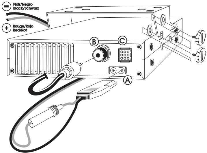
- Connect the antenna (B).
c) Fixed antenna :
- A fixed antenna should be installed in a clear space as possible. If it is fixed to a mast, it will perhaps be necessary to stay it, according to the laws in force (you should seek professional advice).
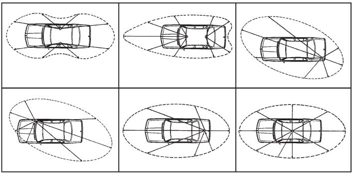
OUTPUT RADIUS PATTERNS
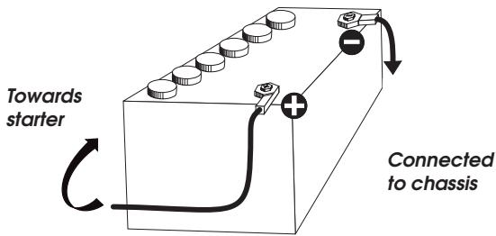
Your PRESIDENT LINCOLN is protected against an inversion of polarities. However, before switching it on, you are advised to check all the connections. Your equipment must be supplied with a continued current of 12 volts (A). Today, most cars and lorries are negative earth. You can check this by making sure that the negative terminal of the battery is connected either to the engine block or to the chassis. If this is not the case, you should consult your dealer.
WARNING : Lorries generally have two batteries and an electrical installation of 24 volts, in which case it will be necessary to insert a 24/12 volt converter (type CV 24/12 PRESIDENT) into the electrical circuit. The following connection steps should be carried out with the power cable disconnected from the set.
a) Check that the battery is of 12 volts.
b) Locate the positive and negative terminals of the battery (+ is red and - is black). Should it be necessary to lengthen the power cable, you should use the same or a superior type of cable.
c) It is necessary to connect your radioto a permanent (+) and (-) . We advise you to connect the power cable directly to the battery (as the connection of the radio cable to the wiring of the car-radio or other parts of the electrical circuit may, in some cases, increase the likelihood of interference).
d) Connect the red wire (+) to the positive terminal of the battery and the black (-) wire to the negative terminal of the battery.
e) Connect the power cable to your radio.
WARNING: Never replace the original fuse by one of a different value.
4) BASIC OPERATIONS TO BE CARRIED OUT BEFORE USING YOUR SET FOR THE FIRST TIME (without transmitting and without using the "push-to-talk" switch on the microphone):
a) Connect the microphone
b) Check the antenna connections
c) Turn the set on by turning the knob (1) clockwise.
d) Turn the squelch knob to minimum (anti-clockwise). Adjust the volume to a comfortable level.
5) HOW TO ADJUST SWR (Standing Wave Ratio):
With the integrated SWR meter:
Put the unit into AM or FM. Using 12) VFO position the unit in the middle of the band (you are advised to check the values obtained on the extreme frequencies, in all cases it is necessary to calibrate). Check that 3) RF POWER is at maximum.
Calibration:
Press 14) INDIC until a small triangle and CAL appear in the display. Keep the PPT switch depressed and, using 2) SWR CAL, bring the bar graph to the same level as the triangle. When you have done this, you are ready to take an SWR reading as described below.
Reading:
Once the SWR Meter has been calibrated (as above), press 14) INDIC until SWR appears in the display. Press the PTT switch on the microphone, the bar graph will show the SWR value. It should be taken from the bottom figures and should be as close to 1 as possible, a value of above 2 may damage your set (destruction of the power amplifier).
This control is used to select the desired mode: AM, FM, LSB, USB or CW.
The mode chosen must correspond to that of the person with whom you communicate.
Amplitude modulation/AM: For communicating in areas where there are obstacles and over medium distances.
Frequency modulation/FM: is used for nearby communications in flat open areas, and gives better quality communications, but squelch is harder to adjust.
Lower Side Band/LSB and Upper Side Band/USB: are used for prompt communications over long distances (depending on atmospheric conditions).
CW : coded in Morse. In order to use this mode, an external key is necessary. For your comfort, the LINCOLN has an integrated one tone oscillator.
2) SWR CAL:
This control is used to calibrate the integrated SWR meter.
See section 14) INDIC.
3) RF POWER:
This control enables you to adjust RF power continuously avar a range of about 1 Watt to 10 Watt in AM, FM and CW.
When you turn thisknob fully clockwise RF power is at maximum. You should reduce output power when communicating with someone close by and who is not equipped with an RF Gain function.
4) RIT:
This knob is used in modes USB, LSB or CW to fine tune the reception signal in order to obtain maximum clarity. This knob can tune the received frequency about +/- 2.3kHz . This control will not effect the transmitting frequency, or the frequency display, but changes only the reception frequency.
5) ON/OFF - VOLUME CONTROL:
Use this control to turn the unit on or off and to adjust the volume.
6) SQUELCH:
This control is used to suppress undesirable background noise when there is no communication. Turn the squelch knob clockwise to the exact point where all background noise disappears. This adjustment should be done with precision as, if set to maximum, only the strongest of signals can be received. Squelch does not effect either sound nor transmission power, but allows for considerable improvement in listening comfort. To use the automatic squelch, turn the control to the position AUTO (anti clockwise until it clicks).
7) LOC/DX Switch:
This is used to vary the RF input to the receiver, to help eliminate strong, adjacent signals.
8) PA (Public Address):
An external loud speaker can be connected to your LINCOLN by using the plug situated on the back panel PA.SP (C). By pressing the PA key, the message transmitted into the microphone will be directed towards the external speaker and be amplified. Hold the microphone far enough away from this loud speaker so as to avoid the Larsen effect.
Press this button once to activate the function. To cancel, depress the same key.
9) CHANNEL SELECTOR: CHANNEL ▲ and ▼:
The two keys are available on the front panel and on the microphone CHANNEL and allow you to step up or down to the next 10 KHz channel. This can also be done using the rotary channel knob.
The selected channel is displayed next to the frequency display. These keys can select any 10 KHz channel within a band (50 channels in Band a : 28,0000 to 28.4900, in band b : 28.5000 to 28.9900, in band c : 29.0000 to 29.4900 and 20 channels in band d : 29.5000 to 29.6900 MHz). The step of 10 KHz is preprogrammed and cannot be changed. When stepping up or down the channels using the keys CHANNEL s and t, the unit tunes itself to the nearest channel and not to the ± 10 KHz frequency indicated. When you get to channel 50 (or channel 20 in band d ), by pressing the button CHANNEL ▲, the set will go to channel 1 of the current band, and if you are on channel 1 and you depress CHANNEL▼, the set will go to channel 50 (or channel 20 in band d ).
10)BAND:
Use this knob to select one of the following band segments.
a:28.0000 to 28.4999 MHz
b:28.5000 to 28.9999 MHz
c:29.0000 to 29.4999 MHz
d:29.5000 to 29.6999 MHz.
Press this button until the letter of the required band shows in the display (the letter is displayed above the channel number). See Section «Display»
11)SPAN:
This control, used with 12) VFO, allows you to select the frequency with precision which can be adjusted by steps of either 10kHz , 1kHz or 100Hz . The selected step is indicated by a line under the relevant digit on the frequency display.
12)VFO: (Variable Frequency Oscillator)
Use this control to select the transmitting and receiving frequency. First check that the button 15) F-LOCK is not depressed and then turn the rotary knob to obtain the desired frequency. In order to change the frequency step, press 11) SPAN so that the underlining shows under the digit required. Tuning is continuous throughout the entire range of the LINCOLN there is no need to select band segments. See Section «Display»
13)NB:
Noise Blanker/Automatic Noise Limiter. This filter allows the reduction of background noise and some reception interference. It also helps to eliminate interference generated by the ignition system of vehicles.
14)INDIC SWITCH:
This switch is used to select the mode for the multi function meter:
a) Position RF: Indicates the received signal strength and transmitted power.
b) Position MOD: Gives you an indication of the strength of your modulation when transmitting (there is no function for this meter in reception).
c) Position s: to calibrate the SWR meter. See how to regulate SWR.
d) Position SWR: SWR reading. See how to regulate SWR.
In reception mode (RX), this key is locked into position RF. Each time you press this key, the next function is selected in the given order. The selected mode is shown on the display.
15)F-LOCK:
Pressing the Frequency Lock button will disable all the frequency determining controls on the front panel, in order to prevent any accidental changes of frequency.
16)MIC GAIN:
Pressing this switch activates the built-in microphone attenuator. This feature is designed to be used when operating the LINCOLN in high ambient noise environments.
When you finish speaking and you release the «push to talk» switch to allow your correspondent to speak, a «beep» sounds. Amateur radio is what is known as a «simplex» method of communication, that is to say that you cannot listen and speak at the same time (as you can, for example, with the telephone). It was custom to say «Roger» to indicate to your correspondent that you had finished speaking and that it was his turn to talk. The word «Roger» has now been replaced with a «beep», hence its name «Roger Beep». Press this key once to activate ROGER BEEP. To cancel out the beep, depress the same key. This key has no function in mode CW.
18)DIM:
This key allows you to adjust the luminosity of the display.
19)SCAN:
This function allows you to "scan" the 50 channels of the chosen band and to find the active channels. It is possible to scan 50 channels in Bands a, b, c and 20 channels in band d. Scanning always starts with the lowest channels and moves upwards to the higher ones, and always by steps of 10 KHz.
To start scanning, press SCAN. Scanning commences, and stops on an active frequency, depending on the squelch level. At the end of the transmission, the LINCOLN waits for about 1.5 seconds before resuming the scan cycle. If you want to communicate the PTT switch on the microphone during the 1.5 seconds. To exit from the scan mode, press the SCAN button.
DISPLAY
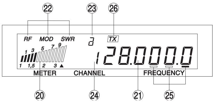
20)MULTI-FUNCTION METER:
This meter can display:
RF: reading of the output power and the reception level.
MOD: works only in transmission mode (TX). Allows you to measure the modulation level and the correct working of the microphone.
A: to calibrate the SWR meter
SWR: reading of the SWR value.
21)FREQUENCY DISPLAY:
Indicates the frequencies chosen.
22)RF/MOD/SWR DISPLAY:
Indicates the mode chosen:
23) BAND DISPLAY a / b / c / d
Indicates the band you have selected.
24) CHANNEL:
Indicates the channel you have selected.
25)VFO STEP INDICATOR:
Displays the currently selected VFO step (the example shows 100 Hz step selected).
26)TX INDICATOR:
Lights to indicate when the radio is in transmitting mode (TX).
Is situated on the front panel of the unit in order to ease integration into the dash board. See wiring diagram on page 41
28)PTT switch on the MICROPHONE:
Press to transmit and release to receive.
- When using the internal speaker only, insert the plug with a short wire between pins 1 and 7.
- Between pins 1 and 2, an external speaker can be connected.
- Pins 4 and 8 allow to link a PA-speaker.
- Pins 8 and 9 serve to connect Morse key.
- Pins 3, 5 and 6 are not used.
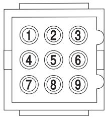
See wiring diagram on page 41
C) TECHNICAL CHARACTERISTICS:
1) GENERAL:
- Channels
- Modulation modes
- Frequency ranges
- Antenna impedance
- Power supply
- Dimensions (in mm)
- Weight
- Accessories supplied
2) TRANSMISSION:
- Frequency allowance
-
Carrier power
-
Transmission interference
- Audio response
- Microphone sensitivity
-Drain - Modulated signal distortion
3) RECEPTION:
Maxi. sensitivity at 20 dB sinad
- Frequency response
Maximum audio power
- Squelch sensitivity
- Freq. image rejection rate
-Drain
:170
: AM/FM/SSB/CW
: from 26 MHz to 29.7
: 50 ohms
: 13.2 V
: 185 (B) x 250 (H) x 60 (T)
: ca 2,0 kg
: microphone UP/DOWN with support, mounting cradle, screwsand fused power cord.
+ / - 300Hz
: 10 Watts AM/FM/CW
: 21 Watts SSB
: inferior to -50 dBc
: 300 Hz - 3 kHz AM/FM/SSB
: 0,6 mV
: 4,5 A (with modulation)
:2.5%
: 0.5 V - 113 dBm (AM/FM)
0.4 V -115 dBm (SSB)
: 300Hz to 3kHz in AM/FM/SSB
:4W
mini 0.5 V -maxi 1 mV
:70dB
: 1 Anomal
D) BREAKDOWN GUIDE:
1) YOUR RADIO WILL NOT TRANSMIT OR YOUR TRANSMISSION IS OF POOR QUALITY:
- Check that the PA function is turned off.
- Check that the antenna is correctly connected and that the SWR is properly adjusted.
- Check that the microphone is properly plugged in.
2) YOUR RADIO WILL NOT RECEIVE OR RECEPTION IS POOR:
- Check that the PA function is not activated
- Check that the squelch level is properly adjusted.
- Check that the volume is set to a comfortable listening level.
- Check that the microphone is properly plugged in.
- Check that the antenna is correctly connected and that the SWR is properly adjusted.
- Check that you are using the same modulation mode as your correspondent.
- Check the power supply.
- Check the connection wiring.
- Check the fuse.